Information hydraulic governor
BOSCH
F 019 Z2E 215
f019z2e215
ZEXEL
105856-3221
1058563221
Rating:
Components :
| 0. | INJECTION-PUMP ASSEMBLY | 105856-3221 |
| 1. | _ | |
| 2. | FUEL INJECTION PUMP | |
| 3. | NUMBER PLATE | |
| 4. | _ | |
| 5. | CAPSULE | |
| 6. | ADJUSTING DEVICE | |
| 7. | NOZZLE AND HOLDER ASSY | |
| 8. | Nozzle and Holder | |
| 9. | Open Pre:MPa(Kqf/cm2) | |
| 10. | NOZZLE-HOLDER | |
| 11. | NOZZLE |
Scheme ###:
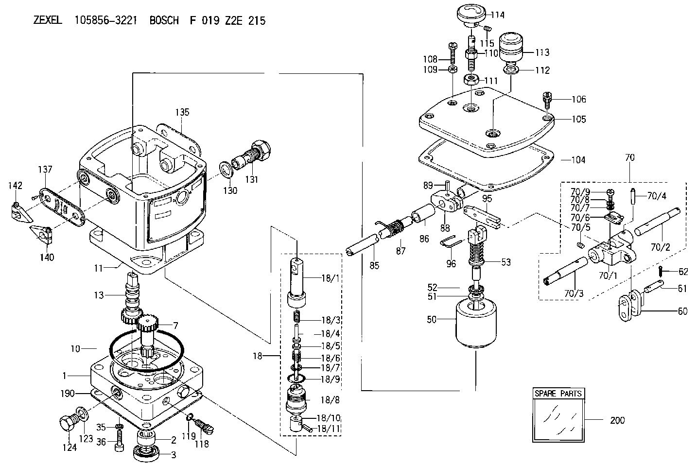
| 1. | [1] | 158502-0420 | BASE |
| 2. | [1] | 029811-8000 | BEARING PLATE |
| 3. | [1] | 158528-0900 | PACKING RING |
| 7. | [1] | 158131-0100 | GEAR SHAFT |
| 10. | [1] | 158028-0000 | O-RING |
| 11. | [1] | 158507-1820 | DIAPHRAGM HOUSING |
| 13. | [1] | 158621-0500 | SLEEVE |
| 18. | [1] | 158699-0321 | COMPENSATOR ASSY |
| 18/1. | [1] | 158610-0901 | POWER PISTON |
| 18/3. | [1] | 158654-0400 | COILED SPRING |
| 18/4. | [1] | 158614-0300 | STOP PIN |
| 18/5. | [1] | 158612-0500 | PLAIN WASHER |
| 18/6. | [1] | 158654-0500 | COILED SPRING |
| 18/7. | [1] | 016110-1220 | LOCKING WASHER |
| 18/8. | [1] | 158612-0001 | BUSHING |
| 18/9. | [2] | 158528-1300 | O-RING |
| 18/10. | [1] | 158615-0300 | PUMP PLUNGER |
| 18/11. | [1] | 025620-1410 | SPRING PIN |
| 35. | [3] | 029330-6070 | GASKET |
| 36. | [3] | 010206-2520 | HEX-SOCKET-HEAD CAP SCREW |
| 50. | [1] | 158600-0720 | FLYWEIGHT ASSEMBLY |
| 51. | [1] | 158106-0100 | PLAIN WASHER |
| 52. | [1] | 029811-0000 | BEARING PLATE |
| 53. | [1] | 158620-1320 | PILOT VALVE |
| 60. | [2] | 158220-0000 | GUIDE LEVER |
| 61. | [2] | 158736-0200 | BEARING PIN |
| 62. | [4] | 025520-1510 | SPLIT PIN |
| 70. | [1] | 158730-0220 | TERMINAL ARM |
| 70/1. | [1] | 158230-0020 | TERMINAL ARM |
| 70/2. | [1] | 158315-0200 | TERMINAL SHAFT |
| 70/3. | [1] | 158315-0200 | TERMINAL SHAFT |
| 70/4. | [2] | 158736-0100 | TAPER PIN |
| 70/5. | [2] | 011006-0620 | SET OF NUTS |
| 70/6. | [1] | 158214-0020 | SPEED DROOP ADJUSTER |
| 70/7. | [1] | 014020-5120 | PLAIN WASHER |
| 70/8. | [1] | 029320-5030 | TAB WASHER |
| 70/9. | [1] | 010535-1220 | FLAT-HEAD SCREW |
| 85. | [1] | 158814-0900 | SPEED CONTROL SHAFT |
| 86. | [2] | 158823-0300 | BUSHING |
| 87. | [1] | 158322-0200 | COILED SPRING |
| 88. | [1] | 158710-0400 | STRAP |
| 89. | [1] | 029404-5010 | BEARING PIN |
| 95. | [1] | 158211-0100 | STRAP |
| 96. | [2] | 158653-0100 | WIRE |
| 104. | [1] | 158017-0900 | GASKET |
| 105. | [1] | 158562-8720 | COVER |
| 106. | [4] | 029010-6350 | BLEEDER SCREW M6P1.0L22 |
| 108. | [1] | 158567-1200 | SET OF NUTS |
| 109. | [1] | 013020-6040 | UNION NUT M6P1H5 |
| 110. | [1] | 158567-1400 | SET OF NUTS |
| 111. | [1] | 158567-1300 | UNION NUT |
| 112. | [1] | 026512-1640 | GASKET D15.9&12.2T1 |
| 113. | [1] | 378050-6120 | AIR FILTER |
| 114. | [1] | 158904-1920 | ROUND NUT |
| 115. | [1] | 011206-1020 | SET OF NUTS |
| 118. | [1] | 158027-0100 | NEEDLE VALVE |
| 119. | [1] | 016500-0710 | O-RING |
| 123. | [2] | 026512-1640 | GASKET D15.9&12.2T1 |
| 124. | [2] | 029111-2070 | CAPSULE M12P1.5L10 |
| 130. | [1] | 029331-8040 | GASKET |
| 131. | [1] | 158660-0020 | CONTROL VALVE |
| 135. | [1] | 158515-0700 | INDICATOR PLATE |
| 137. | [1] | 158515-0800 | INDICATOR PLATE |
| 140. | [2] | 158820-0620 | POINTER |
| 142. | [2] | 158820-0620 | POINTER |
| 190. | [1] | 158017-1000 | GASKET |
| 200. | [1] | 158599-6720 | SPARE PART |
Include in #2:
105856-3221
as INJECTION-PUMP ASSEMBLY
Cross reference number
Zexel num
Bosch num
Firm num
Name
Information:
1. Make a setting of the fuel injection pump timing. See REMOVE FUEL INJECTION PUMP HOUSING AND GOVERNOR for timing procedure. Tools (A) and (B) will be needed to make a setting of the timing. 2. Remove nuts (1). Remove cover (2) from the timing gear cover. Earlier automatic timing advances had only one bolt. 3. Remove bolts (3) and washer (4). Remove automatic timing advance (5).Install Automatic Timing Advance
1. Put automatic timing advance (1) in position on the drive shaft for the fuel injection pump. On earlier engines, tighten the one bolt to 15 lb. ft. (20 N m). Remove tool (A) and tighten the one bolt to a last torque of 110 10 lb. ft. (149 14 N m). 2. Install washer (2) and bolts (3). Tighten bolts (3) in the following sequence: a) Tighten bolts (3) to a torque of 25 lb. ft. (35 N m).b) Remove tool (A).c) Tighten bolts (3) to a torque of 50 lb. ft. (70 N m).d) Tighten bolts (3) to a torque of: Unit with flat retainer ... 80 5 lb. ft.(110 7 N m)Unit with step retainer ... 100 5 lb. ft.(135 7 N m)
Do not tighten the bolts to final torque until tool (A) is removed.
3. Remove the timing bolt from the flywheel.4. Turn the crankshaft two complete revolutions and check the timing to see that the timing is correct.5. Remove the timing bolt from the flywheel. Remove tool (A) and install the plug in the fuel injection pump housing. 6. Install cover (4) and the nuts that hold the cover to the timing gear cover. Disassemble Automatic Timing Advance
start by:a) remove automatic timing advance 1. Remove ring (2) and gear (1) from flange. 2. Remove springs (3) and counterweights (4) from flange.3. Remove slides from dowels on the flange.Assemble Automatic Timing Advance
1. Install slides (1) on to dowels.2. Install the counterweights (2) on the flange. 3. Install the springs (3).4. Install the gear on flange.5. Install the ring that holds gear and flange together. end by: a) install automatic timing advance