Information hydraulic governor
BOSCH
F 019 Z2E 205
f019z2e205
ZEXEL
105856-3090
1058563090
Rating:
Components :
| 0. | INJECTION-PUMP ASSEMBLY | 105856-3090 |
| 1. | _ | |
| 2. | FUEL INJECTION PUMP | |
| 3. | NUMBER PLATE | |
| 4. | _ | |
| 5. | CAPSULE | |
| 6. | ADJUSTING DEVICE | |
| 7. | NOZZLE AND HOLDER ASSY | |
| 8. | Nozzle and Holder | |
| 9. | Open Pre:MPa(Kqf/cm2) | |
| 10. | NOZZLE-HOLDER | |
| 11. | NOZZLE |
Scheme ###:
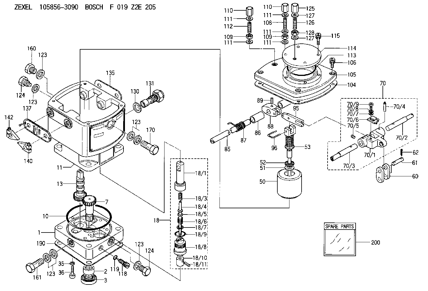
| 1. | [1] | 158502-0620 | BASE |
| 2. | [1] | 029811-8000 | BEARING PLATE |
| 3. | [1] | 158528-0900 | PACKING RING |
| 7. | [1] | 158131-0100 | GEAR SHAFT |
| 10. | [1] | 158028-0000 | O-RING |
| 11. | [1] | 158507-1420 | DIAPHRAGM HOUSING |
| 13. | [1] | 158621-0500 | SLEEVE |
| 18. | [1] | 158699-0321 | COMPENSATOR ASSY |
| 18/1. | [1] | 158610-0901 | POWER PISTON |
| 18/3. | [1] | 158654-0400 | COILED SPRING |
| 18/4. | [1] | 158614-0300 | STOP PIN |
| 18/5. | [1] | 158612-0500 | PLAIN WASHER |
| 18/6. | [1] | 158654-0500 | COILED SPRING |
| 18/7. | [1] | 016110-1220 | LOCKING WASHER |
| 18/8. | [1] | 158612-0001 | BUSHING |
| 18/9. | [2] | 158528-1300 | O-RING |
| 18/10. | [1] | 158615-0300 | PUMP PLUNGER |
| 18/11. | [1] | 025620-1410 | SPRING PIN |
| 35. | [3] | 029330-6070 | GASKET |
| 36. | [3] | 010206-2520 | HEX-SOCKET-HEAD CAP SCREW |
| 50. | [1] | 158600-0720 | FLYWEIGHT ASSEMBLY |
| 51. | [1] | 158106-0100 | PLAIN WASHER |
| 52. | [1] | 029811-0000 | BEARING PLATE |
| 53. | [1] | 158620-1120 | PILOT VALVE |
| 60. | [1] | 158720-0000 | GUIDE LEVER |
| 61. | [2] | 158736-0200 | BEARING PIN |
| 62. | [4] | 025520-1510 | SPLIT PIN |
| 70. | [1] | 158730-0920 | TERMINAL ARM |
| 70/1. | [1] | 158230-0020 | TERMINAL ARM |
| 70/2. | [1] | 158815-0700 | TERMINAL SHAFT |
| 70/3. | [1] | 158815-0600 | TERMINAL SHAFT |
| 70/4. | [2] | 158736-0100 | TAPER PIN |
| 70/5. | [2] | 011006-0620 | SET OF NUTS |
| 70/6. | [1] | 158214-0020 | SPEED DROOP ADJUSTER |
| 70/7. | [1] | 014020-5120 | PLAIN WASHER |
| 70/8. | [1] | 029320-5030 | TAB WASHER |
| 70/9. | [1] | 010535-1220 | FLAT-HEAD SCREW |
| 85. | [1] | 158814-1800 | SPEED CONTROL SHAFT |
| 86. | [2] | 158823-0300 | BUSHING |
| 87. | [1] | 158322-0200 | COILED SPRING |
| 88. | [1] | 158710-0400 | STRAP |
| 89. | [1] | 029404-5010 | BEARING PIN |
| 95. | [1] | 158211-0100 | STRAP |
| 96. | [2] | 158653-0100 | WIRE |
| 104. | [1] | 158017-0900 | GASKET |
| 105. | [1] | 158563-0600 | COVER |
| 106. | [4] | 029010-6350 | BLEEDER SCREW M6P1.0L22 |
| 108. | [1] | 158567-1200 | SET OF NUTS |
| 109. | [2] | 013020-6040 | UNION NUT M6P1H5 |
| 109. | [2] | 013020-6040 | UNION NUT M6P1H5 |
| 110. | [2] | 158567-2000 | FLAT-HEAD SCREW |
| 110. | [2] | 158567-2000 | FLAT-HEAD SCREW |
| 111. | [4] | 026506-1040 | GASKET D9.9&6.2T1 |
| 111. | [4] | 026506-1040 | GASKET D9.9&6.2T1 |
| 111. | [4] | 026506-1040 | GASKET D9.9&6.2T1 |
| 111. | [4] | 026506-1040 | GASKET D9.9&6.2T1 |
| 111. | [4] | 026506-1040 | GASKET D9.9&6.2T1 |
| 112. | [2] | 158567-1900 | CAP NUT |
| 113. | [1] | 016510-6510 | O-RING |
| 114. | [1] | 158563-0700 | COVER |
| 115. | [4] | 029010-6340 | BLEEDER SCREW M6P1.0L16 |
| 118. | [1] | 158027-0100 | NEEDLE VALVE |
| 119. | [1] | 016500-0710 | O-RING |
| 123. | [6] | 026512-1640 | GASKET D15.9&12.2T1 |
| 123. | [6] | 026512-1640 | GASKET D15.9&12.2T1 |
| 123. | [6] | 026512-1640 | GASKET D15.9&12.2T1 |
| 123. | [6] | 026512-1640 | GASKET D15.9&12.2T1 |
| 123. | [6] | 026512-1640 | GASKET D15.9&12.2T1 |
| 124. | [2] | 029111-2070 | CAPSULE M12P1.5L10 |
| 124. | [2] | 029111-2070 | CAPSULE M12P1.5L10 |
| 125. | [1] | 158067-0300 | CAP NUT |
| 126. | [1] | 158067-0200 | SET OF NUTS |
| 127. | [2] | 029330-8050 | GASKET |
| 127. | [2] | 029330-8050 | GASKET |
| 128. | [1] | 158565-0000 | UNION NUT |
| 130. | [1] | 029331-8040 | GASKET |
| 131. | [1] | 158660-0520 | CONTROL VALVE |
| 135. | [1] | 158515-0700 | INDICATOR PLATE |
| 137. | [1] | 158515-0800 | INDICATOR PLATE |
| 140. | [1] | 158820-0620 | POINTER |
| 142. | [1] | 158820-0620 | POINTER |
| 160. | [1] | 029111-2070 | CAPSULE M12P1.5L10 |
| 161. | [1] | 158521-0600 | EYE BOLT |
| 170. | [1] | 158521-0700 | EYE BOLT |
| 190. | [1] | 158017-1000 | GASKET |
| 200. | [1] | 158599-5120 | SPARE PART |
Include in #2:
105856-3090
as INJECTION-PUMP ASSEMBLY
Cross reference number
Zexel num
Bosch num
Firm num
Name
Information:
b. Operate vehicle at 60% of rated speed with moderate load until oil and coolant temperatures reach their normal range for operation. If there is a heavy vibration, drive shaft whip, tire bounce, etc., do not continue with dynamometer test until cause of the problem is corrected. Engines that have had new internal parts installed should be operated on a run-in schedule before operation at full load. For run-in schedule information, make reference to General Instructions section of this Service Manual.2. Put transmission in direct gear and the differential in the highest speed ratio. Operate vehicle at maximum engine speed and increase chassis dynamometer load until a speed of 50 rpm less than rated speed is reached (continuity light should be on). Maintain this speed for one minute and record the engine speed and wheel horsepower. If horsepower is low and poor maintenance is suspected, remove air cleaner or inlet piping to turbocharger and check horsepower again to see if a plugged air cleaner could be the problem.3a. If the wheel horsepower is correct, find the balance point of the engine (speed at which the rack adjustment screw just touches the torque spring or stop bar). At this point the continuity light should flicker (go off and on dimly). If the balance point is correct, then the low power complaint can not be validated. No further test or repairs are necessary.If the balance point is low, see Procedure No. 5.3b. If the wheel horsepower is below the correct value, find the balance point of the engine (speed at which the rack adjustment screw just touches the torque spring or stop bar). At this point the continuity light should flicker (go off and on dimly). If the balance point is correct, see Procedure No. 6If the balance point is low, see Procedure No. 4.4. Stop the engine. Remove the AFRC (air-fuel ratio control). Put a cover over the hole where the AFRC was installed. Start the engine and check the balance point and horsepower again. If both of these are now correct, the problem is in AFRC. Repair or replace the AFRC. If, with the AFRC removed, horsepower is now acceptable and balance point is low, the problem is still with AFRC. Repair or replace the AFRC. Then adjust balance point according to Procedure No. 5.5. If the balance point is low, the high idle will have to be increased to raise the balance point to the correct rpm (the point at which the continuity light just comes on). If the balance point is still low and high idle has been adjusted to maximum, disengage clutch while maximum throttle position is maintained. Now observe high idle rpm and, if lower than previously adjusted, check frame-to-engine-mount. A damaged or loose engine mount may put the linkage in a bind and thus prevent maximum governor position at load conditions.6. If the balance point was correct and the wheel horsepower was low, install the 4S6553 Engine Test Group and do the wheel