Information hydraulic governor
BOSCH
F 019 Z2E 193
f019z2e193
ZEXEL
105856-2940
1058562940
Rating:
Components :
| 0. | INJECTION-PUMP ASSEMBLY | 105856-2940 |
| 1. | _ | |
| 2. | FUEL INJECTION PUMP | |
| 3. | NUMBER PLATE | |
| 4. | _ | |
| 5. | CAPSULE | |
| 6. | ADJUSTING DEVICE | |
| 7. | NOZZLE AND HOLDER ASSY | |
| 8. | Nozzle and Holder | |
| 9. | Open Pre:MPa(Kqf/cm2) | |
| 10. | NOZZLE-HOLDER | |
| 11. | NOZZLE |
Scheme ###:
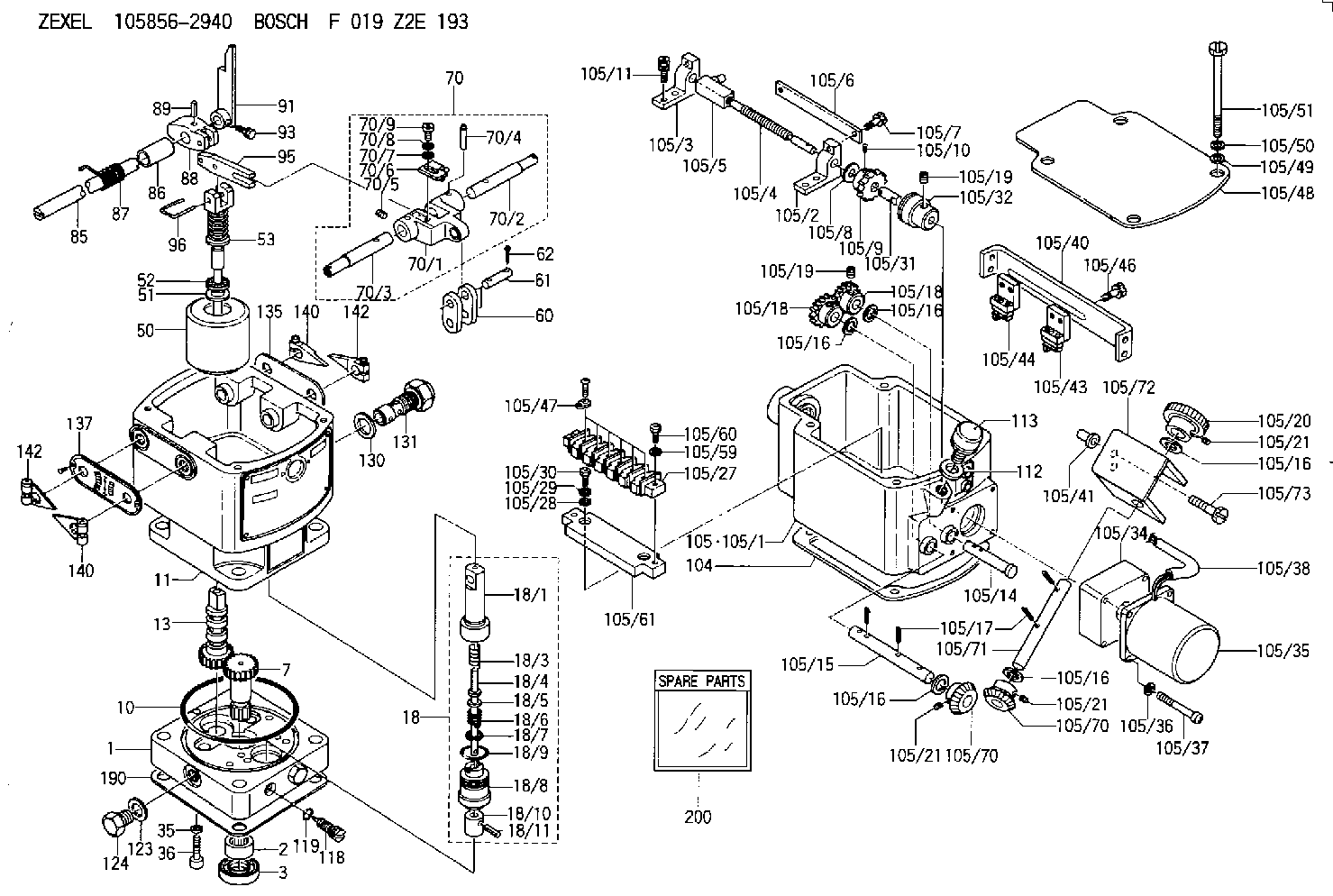
| 1. | [1] | 158502-0420 | BASE |
| 2. | [1] | 029811-8000 | BEARING PLATE |
| 3. | [1] | 158528-0900 | PACKING RING |
| 7. | [1] | 158131-0100 | GEAR SHAFT |
| 10. | [1] | 158028-0000 | O-RING |
| 11. | [1] | 158507-1820 | DIAPHRAGM HOUSING |
| 13. | [1] | 158621-0500 | SLEEVE |
| 18. | [1] | 158699-0321 | COMPENSATOR ASSY |
| 18/1. | [1] | 158610-0901 | POWER PISTON |
| 18/3. | [1] | 158654-0400 | COILED SPRING |
| 18/4. | [1] | 158614-0300 | STOP PIN |
| 18/5. | [1] | 158612-0500 | PLAIN WASHER |
| 18/6. | [1] | 158654-0500 | COILED SPRING |
| 18/7. | [1] | 016110-1220 | LOCKING WASHER |
| 18/8. | [1] | 158612-0001 | BUSHING |
| 18/9. | [2] | 158528-1300 | O-RING |
| 18/10. | [1] | 158615-0300 | PUMP PLUNGER |
| 18/11. | [1] | 025620-1410 | SPRING PIN |
| 35. | [3] | 029330-6070 | GASKET |
| 36. | [3] | 010206-2520 | HEX-SOCKET-HEAD CAP SCREW |
| 50. | [1] | 158600-0720 | FLYWEIGHT ASSEMBLY |
| 51. | [1] | 158106-0100 | PLAIN WASHER |
| 52. | [1] | 029811-0000 | BEARING PLATE |
| 53. | [1] | 158620-1120 | PILOT VALVE |
| 60. | [2] | 158220-0000 | GUIDE LEVER |
| 61. | [2] | 158736-0200 | BEARING PIN |
| 62. | [4] | 025520-1510 | SPLIT PIN |
| 70. | [1] | 158730-0220 | TERMINAL ARM |
| 70/1. | [1] | 158230-0020 | TERMINAL ARM |
| 70/2. | [1] | 158315-0200 | TERMINAL SHAFT |
| 70/3. | [1] | 158315-0200 | TERMINAL SHAFT |
| 70/4. | [2] | 158736-0100 | TAPER PIN |
| 70/5. | [2] | 011006-0620 | SET OF NUTS |
| 70/6. | [1] | 158214-0020 | SPEED DROOP ADJUSTER |
| 70/7. | [1] | 014020-5120 | PLAIN WASHER |
| 70/8. | [1] | 029320-5030 | TAB WASHER |
| 70/9. | [1] | 010535-1220 | FLAT-HEAD SCREW |
| 85. | [1] | 158814-1200 | SPEED CONTROL SHAFT |
| 86. | [1] | 158823-0300 | BUSHING |
| 87. | [1] | 158322-0200 | COILED SPRING |
| 88. | [1] | 158710-0400 | STRAP |
| 89. | [1] | 029404-5010 | BEARING PIN |
| 91. | [1] | 158712-2000 | CONTROL LEVER |
| 93. | [1] | 029010-5210 | BLEEDER SCREW |
| 95. | [1] | 158211-0100 | STRAP |
| 96. | [2] | 158653-0100 | WIRE |
| 104. | [1] | 158017-0900 | GASKET |
| 105. | [1] | 158963-1220 | GOVERNOR MOTOR ASSY |
| 105/1. | [1] | 158962-4810 | CASE |
| 105/2. | [1] | 158903-0200 | HOLDER |
| 105/3. | [1] | 158903-0300 | HOLDER |
| 105/4. | [1] | 158903-0400 | FLAT-HEAD SCREW |
| 105/5. | [1] | 158903-1720 | ADJUSTER |
| 105/6. | [2] | 158903-0800 | PLATE |
| 105/7. | [4] | 029010-6330 | BLEEDER SCREW M6P1.0L13 |
| 105/8. | [1] | 014020-8140 | PLAIN WASHER D16&8.5T1.2 |
| 105/9. | [1] | 158904-0500 | TOOTHED GEAR |
| 105/10. | [1] | 158590-0000 | BEARING PIN |
| 105/11. | [2] | 020106-1640 | BLEEDER SCREW M6P1.0L14 |
| 105/14. | [1] | 158904-0300 | LEVER SHAFT |
| 105/15. | [1] | 158904-0200 | LEVER SHAFT |
| 105/16. | [1] | 014020-8140 | PLAIN WASHER D16&8.5T1.2 |
| 105/16. | [1] | 014020-8140 | PLAIN WASHER D16&8.5T1.2 |
| 105/16. | [1] | 014020-8140 | PLAIN WASHER D16&8.5T1.2 |
| 105/16. | [1] | 014020-8140 | PLAIN WASHER D16&8.5T1.2 |
| 105/16. | [1] | 014020-8140 | PLAIN WASHER D16&8.5T1.2 |
| 105/17. | [4] | 015320-1540 | SPLIT PIN |
| 105/18. | [2] | 158904-0400 | TOOTHED GEAR |
| 105/18. | [2] | 158904-0400 | TOOTHED GEAR |
| 105/19. | [3] | 011005-0820 | SET OF NUTS |
| 105/19. | [3] | 011005-0820 | SET OF NUTS |
| 105/20. | [1] | 158904-1920 | ROUND NUT |
| 105/21. | [3] | 011206-1020 | SET OF NUTS |
| 105/21. | [3] | 011206-1020 | SET OF NUTS |
| 105/21. | [3] | 011206-1020 | SET OF NUTS |
| 105/27. | [1] | 158906-1900 | TERMINAL BOARD |
| 105/28. | [2] | 014020-4140 | PLAIN WASHER D8&4.5T0.5 |
| 105/29. | [2] | 014110-4440 | LOCKING WASHER |
| 105/30. | [2] | 012154-1040 | FLAT-HEAD SCREW M4P0.7L10 |
| 105/31. | [1] | 158902-0300 | JOINT CONNECTION |
| 105/32. | [1] | 158902-0020 | FRICTION COUPLING |
| 105/34. | [1] | 158908-3200 | GEAR HEAD |
| 105/35. | [1] | 158901-7301 | MOTOR |
| 105/36. | [4] | 014020-4140 | PLAIN WASHER D8&4.5T0.5 |
| 105/37. | [4] | 158901-8100 | FLAT-HEAD SCREW |
| 105/38. | [1] | 158901-2200 | HOSE |
| 105/40. | [1] | 158900-0300 | BRACKET |
| 105/41. | [3] | 158900-0200 | BUSHING |
| 105/42. | [1] | 029010-6350 | BLEEDER SCREW M6P1.0L22 |
| 105/43. | [2] | 158907-2320 | LIMIT SWITCH |
| 105/44. | [1] | 158907-1720 | LIMIT SWITCH |
| 105/46. | [4] | 020144-1240 | BLEEDER SCREW |
| 105/47. | [3] | 158906-0801 | TERMINAL |
| 105/48. | [1] | 158562-4700 | COVER |
| 105/49. | [4] | 014020-6140 | PLAIN WASHER |
| 105/50. | [4] | 014110-6440 | LOCKING WASHER |
| 105/51. | [4] | 158909-0100 | BLEEDER SCREW |
| 105/59. | [2] | 014110-4440 | LOCKING WASHER |
| 105/60. | [2] | 012154-1640 | FLAT-HEAD SCREW |
| 105/61. | [1] | 158906-2000 | SPACER BUSHING |
| 105/70. | [2] | 158904-1800 | TOOTHED GEAR |
| 105/70. | [2] | 158904-1800 | TOOTHED GEAR |
| 105/71. | [1] | 158904-1700 | LEVER SHAFT |
| 105/72. | [1] | 158900-0520 | BRACKET |
| 105/73. | [2] | 029010-6370 | BLEEDER SCREW M6P1.0L28 |
| 112. | [1] | 026512-1640 | GASKET D15.9&12.2T1 |
| 113. | [1] | 155406-0220 | AIR FILTER |
| 118. | [1] | 158027-0100 | NEEDLE VALVE |
| 119. | [1] | 016500-0710 | O-RING |
| 123. | [2] | 026512-1640 | GASKET D15.9&12.2T1 |
| 124. | [2] | 029111-2070 | CAPSULE M12P1.5L10 |
| 130. | [1] | 029331-8040 | GASKET |
| 131. | [1] | 158660-0020 | CONTROL VALVE |
| 135. | [1] | 158515-0700 | INDICATOR PLATE |
| 137. | [1] | 158515-0800 | INDICATOR PLATE |
| 140. | [2] | 158820-0620 | POINTER |
| 140. | [2] | 158820-0620 | POINTER |
| 142. | [2] | 158820-0620 | POINTER |
| 142. | [2] | 158820-0620 | POINTER |
| 190. | [1] | 158017-1000 | GASKET |
| 200. | [1] | 158599-7120 | SPARE PART |
Include in #2:
105856-2940
as INJECTION-PUMP ASSEMBLY
Cross reference number
Zexel num
Bosch num
Firm num
Name
105856-2940
F 019 Z2E 193
HYDRAULIC GOVERNOR
* K
* K
Information:
2. Remove nuts (1) from studs for main bearing caps (2).3. Remove the main bearing caps.4. Install rubber hose over each of the two studs at both ends of the block. This will protect the crankshaft during removal and installation. 5. Remove the crankshaft from the cylinder block. Weight of crankshaft is 300 lb. (136 kg).6. Remove the main bearings from cylinder block and main bearing caps.
If main bearings are not replaced, old bearings must be installed in same location from which they were removed.
Install Crankshaft
1. Put timing marks (1) on all timing gears in alignment.2. Clean surfaces for bearings in cylinder block. Install upper halves of bearings in block. Put clean oil on bearings.
If replacement of the bearings is not made, old bearings must be installed in same location from which they were removed.
3. Clean bearing caps, and install lower halves of bearings in caps. 4. Fasten a hoist to crankshaft and put it into place in the block with "V" mark on crankshaft gear in alignment with "V" mark on cluster gear. 5. Check bearing clearance with wire (A). Install bearing caps, and tighten both nuts to 75 5 lb. ft. (101.7 6.8 N m). Put a mark across the nuts and studs, and turn nuts an additional 120° from mark. Remove caps and check thickness of wire (A) to find bearing clearance. Bearing clearance must be .0035 to .0066 in. (0.089 to 0.168 mm) for new parts. Maximum permissible clearance for used parts is .010 in. (0.25 mm).6. Put clean oil on threads of studs, face of nuts, and lower halves of bearings. Put bearing caps in their respective positions with number on cap same as number on block, and groove in bearing cap on same side as groove in cylinder block. Install nuts and tighten to 75 5 lb.ft. (101.7 6.8 N m). Put a mark across the nuts and studs, and turn nuts an additional 120° from mark. 7. Use indicator group (B) to check the crankshaft end plate as controlled by lower bearing of No. 7 bearing cap. End play with new parts should be .006 to .018 in. (0.15 to 0.46 mm). Maximum permissible end play with used parts is .035 in. (0.89 mm).end by: a) install flywheel housingb) install front coverc) install pistonsd) install engine and torque divider
Have questions with 105856-2940?
Group cross 105856-2940 ZEXEL
Hanshin
Shinko-Engin.
105856-2940
F 019 Z2E 193
HYDRAULIC GOVERNOR