Information hydraulic governor
BOSCH
F 019 Z2E 183
f019z2e183
ZEXEL
105856-2860
1058562860

Rating:
Components :
| 0. | INJECTION-PUMP ASSEMBLY | 105856-2860 |
| 1. | _ | |
| 2. | FUEL INJECTION PUMP | |
| 3. | NUMBER PLATE | |
| 4. | _ | |
| 5. | CAPSULE | |
| 6. | ADJUSTING DEVICE | |
| 7. | NOZZLE AND HOLDER ASSY | |
| 8. | Nozzle and Holder | |
| 9. | Open Pre:MPa(Kqf/cm2) | |
| 10. | NOZZLE-HOLDER | |
| 11. | NOZZLE |
Scheme ###:
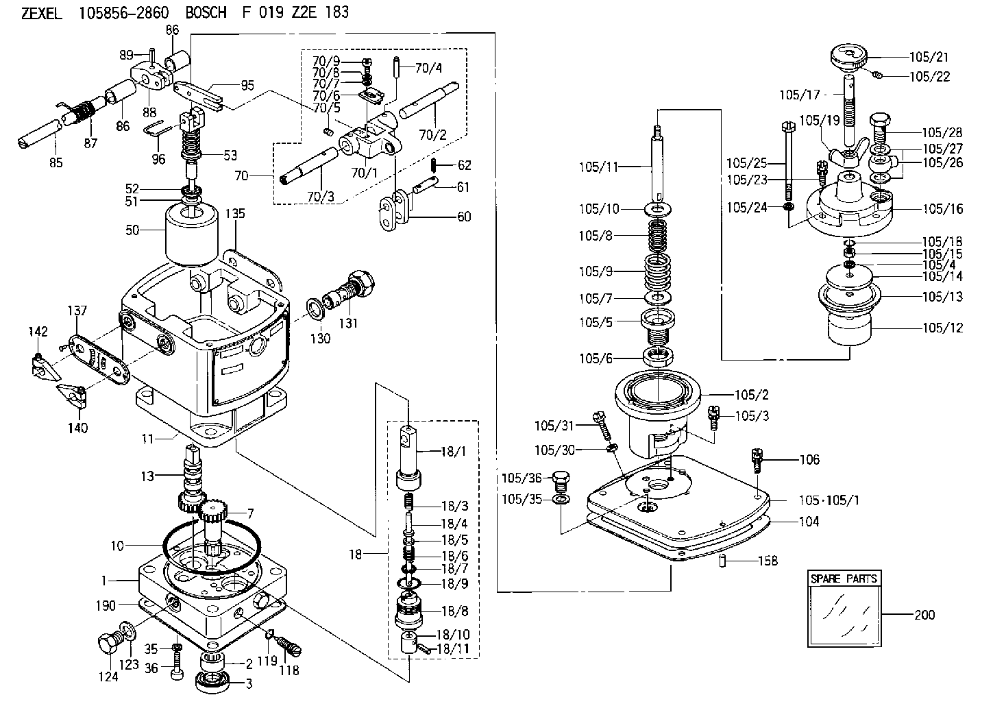
| 1. | [1] | 158502-0420 | BASE |
| 2. | [1] | 029811-8000 | BEARING PLATE |
| 3. | [1] | 158528-0900 | PACKING RING |
| 7. | [1] | 158131-0100 | GEAR SHAFT |
| 10. | [1] | 158028-0000 | O-RING |
| 11. | [1] | 158507-1820 | DIAPHRAGM HOUSING |
| 13. | [1] | 158621-0600 | SLIDING PIECE |
| 18. | [1] | 158699-0521 | COMPENSATOR ASSY |
| 18/1. | [1] | 158610-0901 | POWER PISTON |
| 18/3. | [1] | 158654-1000 | COILED SPRING |
| 18/4. | [1] | 158614-0300 | STOP PIN |
| 18/5. | [1] | 158612-0500 | PLAIN WASHER |
| 18/6. | [1] | 158654-1100 | COILED SPRING |
| 18/7. | [1] | 016110-1220 | LOCKING WASHER |
| 18/8. | [1] | 158612-0001 | BUSHING |
| 18/9. | [2] | 158528-1300 | O-RING |
| 18/10. | [1] | 158615-0400 | PUMP PLUNGER |
| 18/11. | [1] | 025620-1410 | SPRING PIN |
| 35. | [3] | 029330-6070 | GASKET |
| 36. | [3] | 010206-2520 | HEX-SOCKET-HEAD CAP SCREW |
| 50. | [1] | 158600-0720 | FLYWEIGHT ASSEMBLY |
| 51. | [1] | 158106-0100 | PLAIN WASHER |
| 52. | [1] | 029811-0000 | BEARING PLATE |
| 53. | [1] | 158620-1120 | PILOT VALVE |
| 60. | [2] | 158220-0000 | GUIDE LEVER |
| 61. | [2] | 158736-0200 | BEARING PIN |
| 62. | [4] | 025520-1510 | SPLIT PIN |
| 70. | [1] | 158730-0220 | TERMINAL ARM |
| 70/1. | [1] | 158230-0020 | TERMINAL ARM |
| 70/2. | [1] | 158315-0200 | TERMINAL SHAFT |
| 70/3. | [1] | 158315-0200 | TERMINAL SHAFT |
| 70/4. | [2] | 158736-0100 | TAPER PIN |
| 70/5. | [2] | 011006-0620 | SET OF NUTS |
| 70/6. | [1] | 158214-0020 | SPEED DROOP ADJUSTER |
| 70/7. | [1] | 014020-5120 | PLAIN WASHER |
| 70/8. | [1] | 029320-5030 | TAB WASHER |
| 70/9. | [1] | 010535-1220 | FLAT-HEAD SCREW |
| 85. | [1] | 158814-0900 | SPEED CONTROL SHAFT |
| 86. | [2] | 158823-0300 | BUSHING |
| 86. | [2] | 158823-0300 | BUSHING |
| 87. | [1] | 158322-0200 | COILED SPRING |
| 88. | [1] | 158710-0400 | STRAP |
| 89. | [1] | 029404-5010 | BEARING PIN |
| 95. | [1] | 158211-0100 | STRAP |
| 96. | [2] | 158653-0100 | WIRE |
| 104. | [1] | 158017-0900 | GASKET |
| 105. | [1] | 158962-7720 | PNEUMATIC CONTROLLER |
| 105/1. | [1] | 158562-4600 | COVER |
| 105/2. | [1] | 158910-0200 | CYLINDER |
| 105/3. | [3] | 029050-6090 | FLAT-HEAD SCREW |
| 105/4. | [1] | 014110-6440 | LOCKING WASHER |
| 105/5. | [1] | 158416-0000 | FLAT-HEAD SCREW |
| 105/6. | [1] | 158915-0700 | UNION NUT |
| 105/7. | [1] | 158918-0000 | PLAIN WASHER D30&10.8T1.00 |
| 105/8. | [1] | 158412-0300 | COILED SPRING K3.0 |
| 105/9. | [1] | 158912-0600 | COILED SPRING K5.1 |
| 105/10. | [1] | 158918-0000 | PLAIN WASHER D30&10.8T1.00 |
| 105/11. | [1] | 158413-0001 | STOP PIN |
| 105/12. | [1] | 158414-0000 | PUMP PLUNGER |
| 105/13. | [1] | 158414-0100 | DIAPHRAGM |
| 105/14. | [1] | 158414-0200 | PLATE |
| 105/15. | [1] | 013020-6040 | UNION NUT M6P1H5 |
| 105/16. | [1] | 158910-0300 | CAP |
| 105/17. | [1] | 158915-1000 | FLAT-HEAD SCREW |
| 105/18. | [1] | 029630-9050 | O-RING |
| 105/19. | [1] | 158567-1500 | WING NUT |
| 105/21. | [1] | 158904-2020 | ROUND NUT |
| 105/22. | [1] | 158916-0000 | SET OF NUTS |
| 105/23. | [2] | 029050-6220 | FLAT-HEAD SCREW |
| 105/24. | [2] | 029320-6010 | LOCKING WASHER |
| 105/25. | [2] | 158909-0200 | BLEEDER SCREW |
| 105/26. | [1] | 027114-1040 | INLET UNION |
| 105/27. | [2] | 029331-4120 | GASKET D18&14.2T1.5 |
| 105/28. | [1] | 027414-2640 | EYE BOLT |
| 105/30. | [1] | 013020-6040 | UNION NUT M6P1H5 |
| 105/31. | [1] | 158567-1200 | SET OF NUTS |
| 105/35. | [1] | 026512-1640 | GASKET D15.9&12.2T1 |
| 105/36. | [1] | 158066-0000 | BLEEDER SCREW |
| 106. | [4] | 029010-6350 | BLEEDER SCREW M6P1.0L22 |
| 118. | [1] | 158527-0200 | NEEDLE VALVE |
| 119. | [1] | 016500-0710 | O-RING |
| 123. | [2] | 026512-1640 | GASKET D15.9&12.2T1 |
| 124. | [2] | 029111-2070 | CAPSULE M12P1.5L10 |
| 130. | [1] | 029331-8040 | GASKET |
| 131. | [1] | 158660-0420 | CONTROL VALVE |
| 135. | [1] | 158515-0700 | INDICATOR PLATE |
| 137. | [1] | 158515-0800 | INDICATOR PLATE |
| 140. | [1] | 158820-0620 | POINTER |
| 142. | [1] | 158820-0620 | POINTER |
| 158. | [1] | 015040-0880 | BEARING PIN |
| 190. | [1] | 158017-1000 | GASKET |
| 200. | [1] | 158599-6920 | SPARE PART |
Include in #2:
105856-2860
as INJECTION-PUMP ASSEMBLY
Cross reference number
Zexel num
Bosch num
Firm num
Name
Information:
1. Loosen the clamps on hose (3), remove nuts (2) and remove temperature regulator housing (1) and the gasket from the cylinder head. 2. Remove bolt (5) and the nut from the bracket.3. Remove bolts (6) and (7) that hold the fuel injection lines in position. Remove fuel injection lines (4) from the engine.
Put protection caps (5F2807) and plugs (2F2990) on the injection lines and pumps to keep dirt and foreign material out of the fuel system.
4. Disconnect air lines (8) and (9) from the cylinder head. 5. Remove two locks and bolts (10). Remove the dowel used for location of the rear of the camshafts and remove four bolts (12). Remove valve cover base (11) and the gasket from the cylinder head. 6. Remove bolts (14) that hold cylinder head (13) to the cylinder block. 7. Install four 3/8"-16 NC forged eyebolts in the cylinder head as shown. Fasten a hoist and remove the cylinder head. The weight of the cylinder head is 450 lb. (203 kg).8. Remove the water seals and the head gasket from the spacer plate. 9. Remove the O-ring seal from dowel (16).10. Install six 3/8"-16 NC forcing screws in spacer plate (15). Tighten the screws evenly until the spacer plate is free of the dowels. Remove spacer plate (15).11. Remove the second O-ring seal from dowel (16).Install Cylinder Head And Spacer Plate
A new spacer plate gasket must be installed when the cylinder head is removed.1. Thoroughly clean the top surface of the cylinder block, both surfaces of the spacer plate and the bottom surface of the cylinder head. 2. Put the O-ring seal in position around dowel (1).3. Put a new gasket in position on the cylinder block.
Both surfaces of the spacer plate and the top of the cylinder block must be clean. Do not use a gasket adhesive on these surfaces.
4. Install spacer plate (2) on the cylinder block. 5. Install the O-ring seal on the spacer plate around dowel (1).6. Check the cylinder liner projection. See INSTALL CYLINDER LINERS.7. Put a new cylinder head gasket and water seals in position on the spacer plate. 8. Install two 3/4"-10 NC guide bolts 11 in. long in the cylinder block. Install four 3/8"-16 NC forged eyebolts in the cylinder head. Fasten a hoist and put the cylinder head in position on the guide bolts and lower it on the engine. 9. Put 9M3710 Anti-Seize Compound on the threads of cylinder head bolts (3) and the washer faces. Install bolts (3), the washers and tighten as follows: a) Tighten the bolts in number sequence shown to a torque of 200 lb. ft. (270 N m).b) Tighten the bolts in number sequence shown to a torque of 330 10 lb. ft. (447 14 N m). c) Tighten the bolts in number sequence shown (hand tighten) to a torque of 330 10 lb. ft. (447 14 N m). 10. Put the gasket and valve cover base (4) in position on the