Information hydraulic governor
BOSCH
F 019 Z2E 180
f019z2e180
ZEXEL
105856-2831
1058562831
Rating:
Components :
| 0. | INJECTION-PUMP ASSEMBLY | 105856-2831 |
| 1. | _ | |
| 2. | FUEL INJECTION PUMP | |
| 3. | NUMBER PLATE | |
| 4. | _ | |
| 5. | CAPSULE | |
| 6. | ADJUSTING DEVICE | |
| 7. | NOZZLE AND HOLDER ASSY | |
| 8. | Nozzle and Holder | |
| 9. | Open Pre:MPa(Kqf/cm2) | |
| 10. | NOZZLE-HOLDER | |
| 11. | NOZZLE |
Scheme ###:
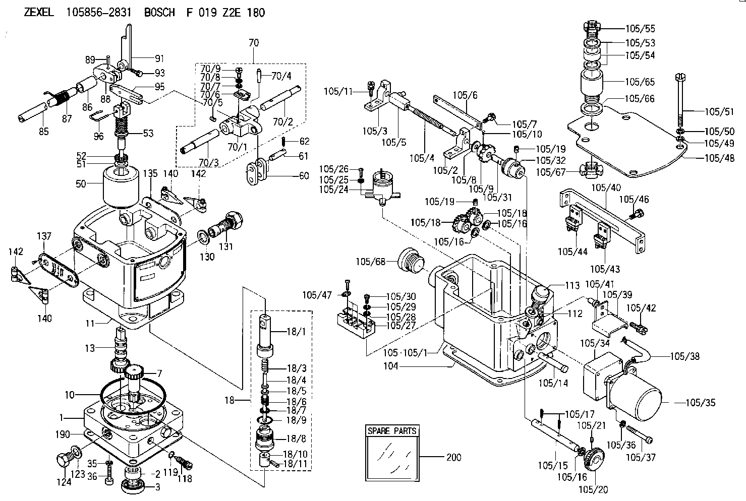
| 1. | [1] | 158502-0420 | BASE |
| 2. | [1] | 029811-8000 | BEARING PLATE |
| 3. | [1] | 158528-0900 | PACKING RING |
| 7. | [1] | 158131-0100 | GEAR SHAFT |
| 10. | [1] | 158028-0000 | O-RING |
| 11. | [1] | 158507-1820 | DIAPHRAGM HOUSING |
| 13. | [1] | 158621-0500 | SLEEVE |
| 18. | [1] | 158699-0321 | COMPENSATOR ASSY |
| 18/1. | [1] | 158610-0901 | POWER PISTON |
| 18/3. | [1] | 158654-0400 | COILED SPRING |
| 18/4. | [1] | 158614-0300 | STOP PIN |
| 18/5. | [1] | 158612-0500 | PLAIN WASHER |
| 18/6. | [1] | 158654-0500 | COILED SPRING |
| 18/7. | [1] | 016110-1220 | LOCKING WASHER |
| 18/8. | [1] | 158612-0001 | BUSHING |
| 18/9. | [2] | 158528-1300 | O-RING |
| 18/10. | [1] | 158615-0300 | PUMP PLUNGER |
| 18/11. | [1] | 025620-1410 | SPRING PIN |
| 35. | [3] | 029330-6070 | GASKET |
| 36. | [3] | 010206-2520 | HEX-SOCKET-HEAD CAP SCREW |
| 50. | [1] | 158600-0720 | FLYWEIGHT ASSEMBLY |
| 51. | [1] | 158106-0100 | PLAIN WASHER |
| 52. | [1] | 029811-0000 | BEARING PLATE |
| 53. | [1] | 158620-1120 | PILOT VALVE |
| 60. | [2] | 158220-0000 | GUIDE LEVER |
| 61. | [2] | 158736-0200 | BEARING PIN |
| 62. | [4] | 025520-1510 | SPLIT PIN |
| 70. | [1] | 158730-0220 | TERMINAL ARM |
| 70/1. | [1] | 158230-0020 | TERMINAL ARM |
| 70/2. | [1] | 158315-0200 | TERMINAL SHAFT |
| 70/3. | [1] | 158315-0200 | TERMINAL SHAFT |
| 70/4. | [2] | 158736-0100 | TAPER PIN |
| 70/5. | [2] | 011006-0620 | SET OF NUTS |
| 70/6. | [1] | 158214-0020 | SPEED DROOP ADJUSTER |
| 70/7. | [1] | 014020-5120 | PLAIN WASHER |
| 70/8. | [1] | 029320-5030 | TAB WASHER |
| 70/9. | [1] | 010535-1220 | FLAT-HEAD SCREW |
| 85. | [1] | 158814-1200 | SPEED CONTROL SHAFT |
| 86. | [1] | 158823-0300 | BUSHING |
| 87. | [1] | 158322-0200 | COILED SPRING |
| 88. | [1] | 158710-0400 | STRAP |
| 89. | [1] | 029404-5010 | BEARING PIN |
| 91. | [1] | 158712-2000 | CONTROL LEVER |
| 93. | [1] | 029010-5210 | BLEEDER SCREW |
| 95. | [1] | 158211-0100 | STRAP |
| 96. | [2] | 158653-0100 | WIRE |
| 104. | [1] | 158017-0900 | GASKET |
| 105. | [1] | 158963-0820 | GOVERNOR MOTOR ASSY |
| 105/1. | [1] | 158962-0410 | CASE |
| 105/2. | [1] | 158903-0200 | HOLDER |
| 105/3. | [1] | 158903-0300 | HOLDER |
| 105/4. | [1] | 158903-0400 | FLAT-HEAD SCREW |
| 105/5. | [1] | 158903-1720 | ADJUSTER |
| 105/6. | [2] | 158903-0800 | PLATE |
| 105/7. | [4] | 029010-6330 | BLEEDER SCREW M6P1.0L13 |
| 105/8. | [1] | 014020-8140 | PLAIN WASHER D16&8.5T1.2 |
| 105/9. | [1] | 158904-0500 | TOOTHED GEAR |
| 105/10. | [1] | 158590-0000 | BEARING PIN |
| 105/11. | [2] | 020106-1640 | BLEEDER SCREW M6P1.0L14 |
| 105/14. | [1] | 158904-0300 | LEVER SHAFT |
| 105/15. | [1] | 158904-0200 | LEVER SHAFT |
| 105/16. | [3] | 014020-8140 | PLAIN WASHER D16&8.5T1.2 |
| 105/16. | [3] | 014020-8140 | PLAIN WASHER D16&8.5T1.2 |
| 105/16. | [3] | 014020-8140 | PLAIN WASHER D16&8.5T1.2 |
| 105/17. | [3] | 015320-1540 | SPLIT PIN |
| 105/18. | [2] | 158904-0400 | TOOTHED GEAR |
| 105/18. | [2] | 158904-0400 | TOOTHED GEAR |
| 105/19. | [3] | 011005-0820 | SET OF NUTS |
| 105/19. | [3] | 011005-0820 | SET OF NUTS |
| 105/20. | [1] | 158904-1920 | ROUND NUT |
| 105/21. | [1] | 158916-0000 | SET OF NUTS |
| 105/24. | [1] | 158908-3900 | CONDENSER |
| 105/25. | [2] | 014110-3440 | LOCKING WASHER |
| 105/26. | [2] | 012153-0840 | FLAT-HEAD SCREW M3P0.5L8 |
| 105/27. | [1] | 158906-0700 | TERMINAL BOARD |
| 105/28. | [2] | 014020-4140 | PLAIN WASHER D8&4.5T0.5 |
| 105/29. | [2] | 014110-4440 | LOCKING WASHER |
| 105/30. | [2] | 012154-1640 | FLAT-HEAD SCREW |
| 105/31. | [1] | 158902-0300 | JOINT CONNECTION |
| 105/32. | [1] | 158902-0020 | FRICTION COUPLING |
| 105/34. | [1] | 158908-3300 | GEAR HEAD |
| 105/35. | [1] | 158908-4200 | MOTOR |
| 105/36. | [4] | 014020-4140 | PLAIN WASHER D8&4.5T0.5 |
| 105/37. | [4] | 158901-8100 | FLAT-HEAD SCREW |
| 105/38. | [1] | 158901-2200 | HOSE |
| 105/39. | [1] | 158901-8300 | COVER |
| 105/40. | [1] | 158900-0300 | BRACKET |
| 105/41. | [3] | 158900-0200 | BUSHING |
| 105/42. | [3] | 029010-6350 | BLEEDER SCREW M6P1.0L22 |
| 105/43. | [1] | 158907-1820 | LIMIT SWITCH |
| 105/44. | [1] | 158907-1720 | LIMIT SWITCH |
| 105/46. | [4] | 020144-1240 | BLEEDER SCREW |
| 105/47. | [1] | 158906-0801 | TERMINAL |
| 105/48. | [1] | 158962-0300 | COVER |
| 105/49. | [4] | 014020-6140 | PLAIN WASHER |
| 105/50. | [4] | 014110-6440 | LOCKING WASHER |
| 105/51. | [4] | 158909-0100 | BLEEDER SCREW |
| 105/53. | [2] | 158401-7300 | GASKET |
| 105/54. | [1] | 158401-7500 | GASKET |
| 105/55. | [1] | 158401-7400 | GROUND |
| 105/65. | [1] | 158901-6200 | ADAPTOR |
| 105/66. | [1] | 158901-6300 | GASKET |
| 105/67. | [1] | 158901-6400 | UNION NUT |
| 105/68. | [1] | 158591-0000 | CAPSULE |
| 112. | [1] | 026512-1640 | GASKET D15.9&12.2T1 |
| 113. | [1] | 155406-0220 | AIR FILTER |
| 118. | [1] | 158027-0100 | NEEDLE VALVE |
| 119. | [1] | 016500-0710 | O-RING |
| 123. | [2] | 026512-1640 | GASKET D15.9&12.2T1 |
| 124. | [2] | 029111-2070 | CAPSULE M12P1.5L10 |
| 130. | [1] | 029331-8040 | GASKET |
| 131. | [1] | 158660-0020 | CONTROL VALVE |
| 135. | [1] | 158515-0700 | INDICATOR PLATE |
| 137. | [1] | 158515-0800 | INDICATOR PLATE |
| 140. | [2] | 158820-0620 | POINTER |
| 140. | [2] | 158820-0620 | POINTER |
| 142. | [2] | 158820-0620 | POINTER |
| 142. | [2] | 158820-0620 | POINTER |
| 190. | [1] | 158017-1000 | GASKET |
| 200. | [1] | 158599-6720 | SPARE PART |
Include in #2:
105856-2831
as INJECTION-PUMP ASSEMBLY
Cross reference number
Zexel num
Bosch num
Firm num
Name
Information:
start by: a) separation of governor from fuel injection pump housing 1. Remove the cover (1) for the rack centering pin. Move the rack until the centering pin can be pushed down. Install the cover so the edge of the cover holds the pin down. 2. Remove the protection cap and felt washer (2).3. Install wrench (A) and remove bushing (3).4. Remove seal (4). 5. Install extractor (B). Hold the rack toward the driven end of the pump housing and remove the fuel injection pump.
Do not remove fuel injection pumps without the rack centering pin installed and the rack held toward the driven end of the pump housing.
6. Remove spacer (10). Put identification on spacers (10), fuel injection pumps, and lifters (14) as to their respective location in the pump housing. These parts must be installed back in their original positions in the pump housing.7. Disassemble injection pumps using the following method: a) Remove bonnet (5), ring (8), spring (7), and check valve (6) from barrel (9).b) Remove plunger assembly (11), washer (12), and spring (13) from barrel (9).
During disassembly and assembly of fuel injection pumps, use much care to prevent damage to the surfaces of plunger assemblies. The barrel and plunger assemblies have a special fit with each other, and are not to be used with other barrels or plunger assemblies.
8. Remove the cover for the rack centering pin. Remove the spring and pin.9. Remove the rack from the pump housing. 10. Remove lifters (14). Put identification on lifters so they can be installed back into their original positions in housing. 11. Remove the bolt, lock and plate (17).12. Remove spring (15) and gear assembly (18) from the camshaft. 13. Remove the camshaft (19) from the pump housing. 14. Install tool group (C) and remove the camshaft bearings from the pump housing.15. Remove the two rack bearings (16) from the pump housing.Assemble Fuel Injection Pump Housing
1. Install camshaft bearings in pump housing with tool group (C). Install the bearing at governor end of pump housing so the oil hole in bearing is in alignment with oil hole in pump housing. Install the two bearings on each end of housing so the edge of bearing will be even with end of pump housing. 2. Install the two rack bearings in pump housing with tooling (D). Install the bearing at governor end of pump housing so it is .195 .005 in. (4.95 0.13 mm) inside end of housing. Install rack bearing at other end of housing so it is even with face of pump housing. If rack bearing at other end of housing has a tab, install with tool group (F).3. Put clean oil on the camshaft and install