Information hydraulic governor
BOSCH
F 019 Z2E 177
f019z2e177
ZEXEL
105856-2780
1058562780
SHINKO-ENGIN.
127100012
127100012

Rating:
Components :
| 0. | INJECTION-PUMP ASSEMBLY | 105856-2780 |
| 1. | _ | |
| 2. | FUEL INJECTION PUMP | |
| 3. | NUMBER PLATE | |
| 4. | _ | |
| 5. | CAPSULE | |
| 6. | ADJUSTING DEVICE | |
| 7. | NOZZLE AND HOLDER ASSY | |
| 8. | Nozzle and Holder | |
| 9. | Open Pre:MPa(Kqf/cm2) | |
| 10. | NOZZLE-HOLDER | |
| 11. | NOZZLE |
Scheme ###:
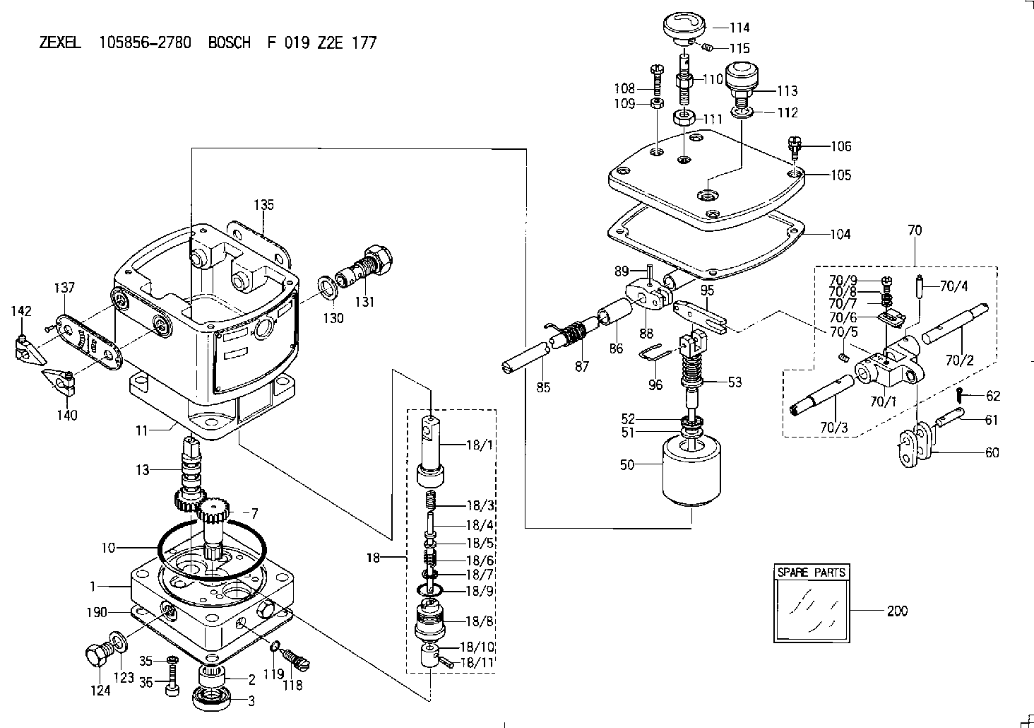
| 1. | [1] | 158502-0420 | BASE |
| 2. | [1] | 029811-8000 | BEARING PLATE |
| 3. | [1] | 158528-0900 | PACKING RING |
| 7. | [1] | 158131-0100 | GEAR SHAFT |
| 10. | [1] | 158028-0000 | O-RING |
| 11. | [1] | 158507-1820 | DIAPHRAGM HOUSING |
| 13. | [1] | 158621-0600 | SLIDING PIECE |
| 18. | [1] | 158699-0521 | COMPENSATOR ASSY |
| 18/1. | [1] | 158610-0901 | POWER PISTON |
| 18/3. | [1] | 158654-1000 | COILED SPRING |
| 18/4. | [1] | 158614-0300 | STOP PIN |
| 18/5. | [1] | 158612-0500 | PLAIN WASHER |
| 18/6. | [1] | 158654-1100 | COILED SPRING |
| 18/7. | [1] | 016110-1220 | LOCKING WASHER |
| 18/8. | [1] | 158612-0001 | BUSHING |
| 18/9. | [2] | 158528-1300 | O-RING |
| 18/10. | [1] | 158615-0400 | PUMP PLUNGER |
| 18/11. | [1] | 025620-1410 | SPRING PIN |
| 35. | [3] | 029330-6070 | GASKET |
| 36. | [3] | 010206-2520 | HEX-SOCKET-HEAD CAP SCREW |
| 50. | [1] | 158600-0720 | FLYWEIGHT ASSEMBLY |
| 51. | [1] | 158106-0100 | PLAIN WASHER |
| 52. | [1] | 029811-0000 | BEARING PLATE |
| 53. | [1] | 158620-1220 | PILOT VALVE |
| 60. | [2] | 158220-0000 | GUIDE LEVER |
| 61. | [2] | 158736-0200 | BEARING PIN |
| 62. | [4] | 025520-1510 | SPLIT PIN |
| 70. | [1] | 158730-0220 | TERMINAL ARM |
| 70/1. | [1] | 158230-0020 | TERMINAL ARM |
| 70/2. | [1] | 158315-0200 | TERMINAL SHAFT |
| 70/3. | [1] | 158315-0200 | TERMINAL SHAFT |
| 70/4. | [2] | 158736-0100 | TAPER PIN |
| 70/5. | [2] | 011006-0620 | SET OF NUTS |
| 70/6. | [1] | 158214-0020 | SPEED DROOP ADJUSTER |
| 70/7. | [1] | 014020-5120 | PLAIN WASHER |
| 70/8. | [1] | 029320-5030 | TAB WASHER |
| 70/9. | [1] | 010535-1220 | FLAT-HEAD SCREW |
| 85. | [1] | 158814-0900 | SPEED CONTROL SHAFT |
| 86. | [2] | 158823-0300 | BUSHING |
| 87. | [1] | 158322-0200 | COILED SPRING |
| 88. | [1] | 158710-0400 | STRAP |
| 89. | [1] | 029404-5010 | BEARING PIN |
| 95. | [1] | 158211-0100 | STRAP |
| 96. | [2] | 158653-0100 | WIRE |
| 104. | [1] | 158017-0900 | GASKET |
| 105. | [1] | 158562-8720 | COVER |
| 106. | [4] | 029010-6350 | BLEEDER SCREW M6P1.0L22 |
| 108. | [1] | 158567-1200 | SET OF NUTS |
| 109. | [1] | 013020-6040 | UNION NUT M6P1H5 |
| 110. | [1] | 158567-1400 | SET OF NUTS |
| 111. | [1] | 158567-1300 | UNION NUT |
| 112. | [1] | 026512-1640 | GASKET D15.9&12.2T1 |
| 113. | [1] | 378050-6120 | AIR FILTER |
| 114. | [1] | 158904-1920 | ROUND NUT |
| 115. | [1] | 011206-1020 | SET OF NUTS |
| 118. | [1] | 158527-0200 | NEEDLE VALVE |
| 119. | [1] | 016500-0710 | O-RING |
| 123. | [2] | 026512-1640 | GASKET D15.9&12.2T1 |
| 124. | [2] | 029111-2070 | CAPSULE M12P1.5L10 |
| 130. | [1] | 029331-8040 | GASKET |
| 131. | [1] | 158660-0020 | CONTROL VALVE |
| 135. | [1] | 158515-0700 | INDICATOR PLATE |
| 137. | [1] | 158515-0800 | INDICATOR PLATE |
| 140. | [2] | 158820-0620 | POINTER |
| 142. | [2] | 158820-0620 | POINTER |
| 190. | [1] | 158017-1000 | GASKET |
| 200. | [1] | 158599-6720 | SPARE PART |
Include in #2:
105856-2780
as INJECTION-PUMP ASSEMBLY
Cross reference number
Zexel num
Bosch num
Firm num
Name
Information:
3. Remove the water outlet elbow (1) from the cooler and the block.4. Remove the oil line (2) from the oil cooler. Disconnect oil inlet line (3) at the cooler.5. Remove the bolts (4) that hold the oil cooler to the water pump housing. Remove bolts (5) that hold the cooler to the block. Remove the oil cooler.Install Oil Cooler (Standard Engine)
1. Put oil cooler (1) in position on the engine. Install bolts at flanges (2) and (3) that hold oil cooler to the engine.2. Install the oil lines to the oil cooler.3. Install the water outlet elbow from the cooler to the engine.4. Fill the engine with oil and coolant to the correct levels.Remove And Install Oil Cooler (With BrakeSaver)
The oil cooler on an engine with a BrakeSaver is not always in the same location on all trucks.1. Drain the coolant from the engine.2. Drain the oil from the oil cooler. 3. Remove oil filler pipe (1) and the gasket from the engine.4. Remove the bolts that hold oil level gauge assembly (3) in position and remove it from the engine.5. Remove elbow (6) and disconnect tube assembly (5) from oil cooler (4).6. Fasten a hoist to oil cooler (4). Remove the bolts that hold the oil cooler to the water pump. Remove the bolts that hold bonnet (2) to the engine and remove the oil cooler. The weight of the oil cooler is 70 lb. (32 kg). 7. Fasten a hoist and put the bonnet and oil cooler (4) and gaskets in position on the engine. Install the bolts that hold the bonnet and oil cooler in position.8. Make sure the seal is in position in tube assembly (5) and connect it to oil cooler (4).9. Install elbow (6) and the seals.10. Install oil filler pipe (1) and oil level gauge assembly (3) on the engine.11. Fill the engine with oil and coolant to the correct levels.