Information hydraulic governor
BOSCH
F 019 Z2E 132
f019z2e132
ZEXEL
105856-2281
1058562281
YANMAR
41100002391
41100002391
Rating:
Components :
| 0. | INJECTION-PUMP ASSEMBLY | 105856-2281 |
| 1. | _ | |
| 2. | FUEL INJECTION PUMP | |
| 3. | NUMBER PLATE | |
| 4. | _ | |
| 5. | CAPSULE | |
| 6. | ADJUSTING DEVICE | |
| 7. | NOZZLE AND HOLDER ASSY | |
| 8. | Nozzle and Holder | |
| 9. | Open Pre:MPa(Kqf/cm2) | |
| 10. | NOZZLE-HOLDER | |
| 11. | NOZZLE |
Scheme ###:
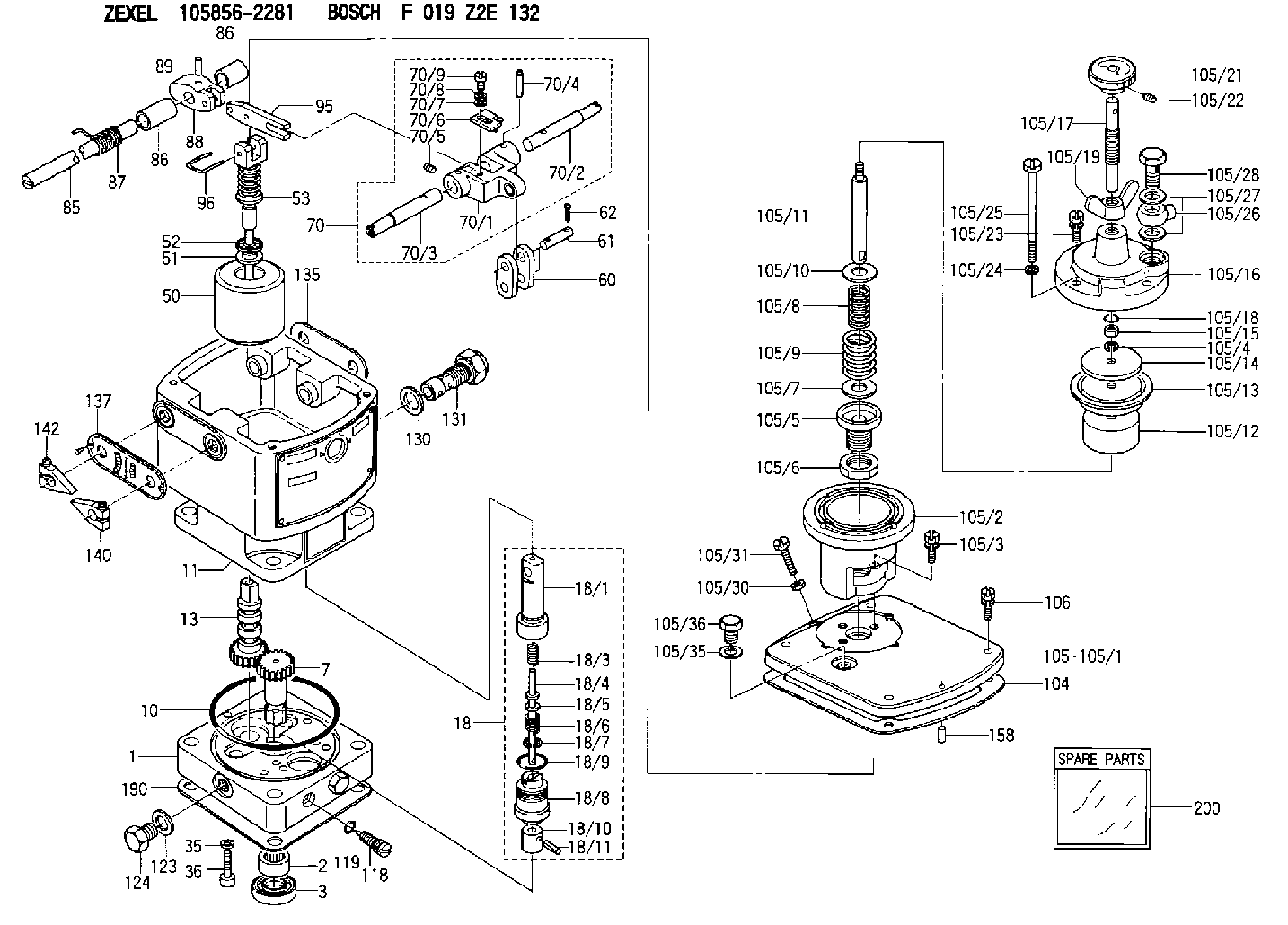
| 1. | [1] | 158502-0420 | BASE |
| 2. | [1] | 029811-8000 | BEARING PLATE |
| 3. | [1] | 158528-0900 | PACKING RING |
| 7. | [1] | 158131-0100 | GEAR SHAFT |
| 10. | [1] | 158028-0000 | O-RING |
| 11. | [1] | 158507-1820 | DIAPHRAGM HOUSING |
| 13. | [1] | 158621-0500 | SLEEVE |
| 18. | [1] | 158699-0321 | COMPENSATOR ASSY |
| 18/1. | [1] | 158610-0901 | POWER PISTON |
| 18/3. | [1] | 158654-0400 | COILED SPRING |
| 18/4. | [1] | 158614-0300 | STOP PIN |
| 18/5. | [1] | 158612-0500 | PLAIN WASHER |
| 18/6. | [1] | 158654-0500 | COILED SPRING |
| 18/7. | [1] | 016110-1220 | LOCKING WASHER |
| 18/8. | [1] | 158612-0001 | BUSHING |
| 18/9. | [2] | 158528-1300 | O-RING |
| 18/10. | [1] | 158615-0300 | PUMP PLUNGER |
| 18/11. | [1] | 025620-1410 | SPRING PIN |
| 35. | [3] | 029330-6070 | GASKET |
| 36. | [3] | 010206-2520 | HEX-SOCKET-HEAD CAP SCREW |
| 50. | [1] | 158600-0720 | FLYWEIGHT ASSEMBLY |
| 51. | [1] | 158106-0100 | PLAIN WASHER |
| 52. | [1] | 029811-0000 | BEARING PLATE |
| 53. | [1] | 158620-1120 | PILOT VALVE |
| 60. | [2] | 158220-0000 | GUIDE LEVER |
| 61. | [2] | 158736-0200 | BEARING PIN |
| 62. | [4] | 025520-1510 | SPLIT PIN |
| 70. | [1] | 158730-0220 | TERMINAL ARM |
| 70/1. | [1] | 158230-0020 | TERMINAL ARM |
| 70/2. | [1] | 158315-0200 | TERMINAL SHAFT |
| 70/3. | [1] | 158315-0200 | TERMINAL SHAFT |
| 70/4. | [2] | 158736-0100 | TAPER PIN |
| 70/5. | [2] | 011006-0620 | SET OF NUTS |
| 70/6. | [1] | 158214-0020 | SPEED DROOP ADJUSTER |
| 70/7. | [1] | 014020-5120 | PLAIN WASHER |
| 70/8. | [1] | 029320-5030 | TAB WASHER |
| 70/9. | [1] | 010535-1220 | FLAT-HEAD SCREW |
| 85. | [1] | 158814-0900 | SPEED CONTROL SHAFT |
| 86. | [2] | 158823-0300 | BUSHING |
| 86. | [2] | 158823-0300 | BUSHING |
| 87. | [1] | 158322-0200 | COILED SPRING |
| 88. | [1] | 158710-0400 | STRAP |
| 89. | [1] | 029404-5010 | BEARING PIN |
| 95. | [1] | 158211-0100 | STRAP |
| 96. | [2] | 158653-0100 | WIRE |
| 104. | [1] | 158017-0900 | GASKET |
| 105. | [1] | 158962-7720 | PNEUMATIC CONTROLLER |
| 105/1. | [1] | 158562-4600 | COVER |
| 105/2. | [1] | 158910-0200 | CYLINDER |
| 105/3. | [3] | 029050-6090 | FLAT-HEAD SCREW |
| 105/4. | [1] | 014110-6440 | LOCKING WASHER |
| 105/5. | [1] | 158416-0000 | FLAT-HEAD SCREW |
| 105/6. | [1] | 158915-0700 | UNION NUT |
| 105/7. | [1] | 158918-0000 | PLAIN WASHER D30&10.8T1.00 |
| 105/8. | [1] | 158412-0300 | COILED SPRING K3.0 |
| 105/9. | [1] | 158912-0600 | COILED SPRING K5.1 |
| 105/10. | [1] | 158918-0000 | PLAIN WASHER D30&10.8T1.00 |
| 105/11. | [1] | 158413-0001 | STOP PIN |
| 105/12. | [1] | 158414-0000 | PUMP PLUNGER |
| 105/13. | [1] | 158414-0100 | DIAPHRAGM |
| 105/14. | [1] | 158414-0200 | PLATE |
| 105/15. | [1] | 013020-6040 | UNION NUT M6P1H5 |
| 105/16. | [1] | 158910-0300 | CAP |
| 105/17. | [1] | 158915-1000 | FLAT-HEAD SCREW |
| 105/18. | [1] | 029630-9050 | O-RING |
| 105/19. | [1] | 158567-1500 | WING NUT |
| 105/21. | [1] | 158904-2020 | ROUND NUT |
| 105/22. | [1] | 158916-0000 | SET OF NUTS |
| 105/23. | [2] | 029050-6220 | FLAT-HEAD SCREW |
| 105/24. | [2] | 029320-6010 | LOCKING WASHER |
| 105/25. | [2] | 158909-0200 | BLEEDER SCREW |
| 105/26. | [1] | 027114-1040 | INLET UNION |
| 105/27. | [2] | 029331-4120 | GASKET D18&14.2T1.5 |
| 105/28. | [1] | 027414-2640 | EYE BOLT |
| 105/30. | [1] | 013020-6040 | UNION NUT M6P1H5 |
| 105/31. | [1] | 158567-1200 | SET OF NUTS |
| 105/35. | [1] | 026512-1640 | GASKET D15.9&12.2T1 |
| 105/36. | [1] | 158066-0000 | BLEEDER SCREW |
| 106. | [4] | 029010-6350 | BLEEDER SCREW M6P1.0L22 |
| 118. | [1] | 158027-0100 | NEEDLE VALVE |
| 119. | [1] | 016500-0710 | O-RING |
| 123. | [2] | 026512-1640 | GASKET D15.9&12.2T1 |
| 124. | [2] | 029111-2070 | CAPSULE M12P1.5L10 |
| 130. | [1] | 029331-8040 | GASKET |
| 131. | [1] | 158660-0020 | CONTROL VALVE |
| 135. | [1] | 158515-0700 | INDICATOR PLATE |
| 137. | [1] | 158515-0800 | INDICATOR PLATE |
| 140. | [1] | 158820-0620 | POINTER |
| 142. | [1] | 158820-0620 | POINTER |
| 158. | [1] | 015040-0880 | BEARING PIN |
| 190. | [1] | 158017-1000 | GASKET |
| 200. | [1] | 158599-6920 | SPARE PART |
Include in #2:
105856-2281
as INJECTION-PUMP ASSEMBLY
Cross reference number
Zexel num
Bosch num
Firm num
Name
Information:
start by: a) remove flywheelb) remove electric starting motorc) remove air compressord) remove turbochargere) remove oil pan 1. Remove the bolts from collar (2) and elbow (1).2. Remove the bolts from support (3). Remove bolts (4) from behind the support.3. Remove the exhaust manifold and support. Remove O-ring seal (5) from between the support and flywheel housing. 4. Fasten tooling (A) and a hoist to the flywheel housing (6). Remove the bolts that hold the flywheel housing in position. Remove the flywheel housing. Weight of the housing is 80 lb. (36 kg).
Do not cause damage to the crankshaft rear seal when the flywheel housing is removed.
Install Flywheel Housing
1. Install a new gasket on the rear of the engine block. 2. Put clean SAE 30 engine oil on the crankshaft rear seal wear sleeve and on the rear seal (2).3. Fasten a hoist and tooling (A) to flywheel housing (1). Put the flywheel housing in position on the engine block.
Be careful not to cause damage to the rear seal.
4. Install the bolts that hold the flywheel housing to the cylinder block. 5. Remove tooling (A). Install O-ring seal (5) on the oil (supply) hole in the flywheel housing and between the support.6. Put exhaust manifold and support (6) in position on the flywheel housing.7. Put 9M3710 Anti-Seize Compound on the bolts that hold the exhaust manifold and support. Install the bolts in the support.8. Install the gaskets between exhaust manifold collar (4) and at the elbow (3). Install the bolts and nuts that hold the manifolds together.end by: a) install oil panb) install turbochargerc) install air compressord) install electric startere) install flywheel