Information hydraulic governor
BOSCH
F 019 Z2E 070
f019z2e070
ZEXEL
105856-1390
1058561390

Rating:
Components :
| 0. | INJECTION-PUMP ASSEMBLY | 105856-1390 |
| 1. | _ | |
| 2. | FUEL INJECTION PUMP | |
| 3. | NUMBER PLATE | |
| 4. | _ | |
| 5. | CAPSULE | |
| 6. | ADJUSTING DEVICE | |
| 7. | NOZZLE AND HOLDER ASSY | |
| 8. | Nozzle and Holder | |
| 9. | Open Pre:MPa(Kqf/cm2) | |
| 10. | NOZZLE-HOLDER | |
| 11. | NOZZLE |
Scheme ###:
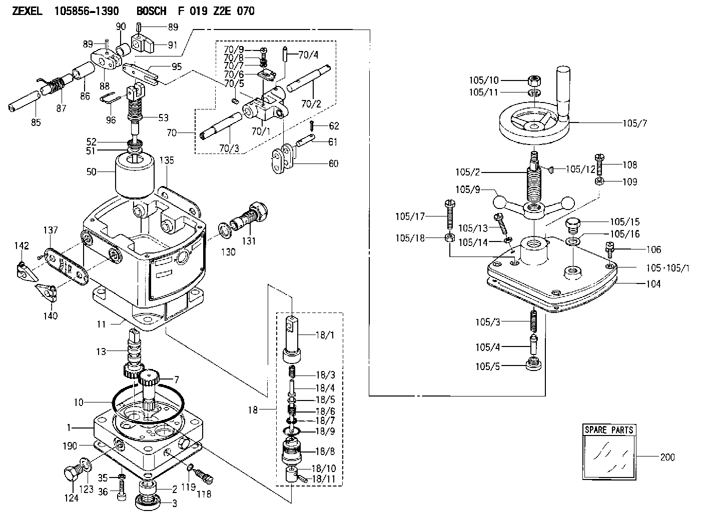
| 1. | [1] | 158502-0420 | BASE |
| 2. | [1] | 029811-8000 | BEARING PLATE |
| 3. | [1] | 158528-0900 | PACKING RING |
| 7. | [1] | 158131-0100 | GEAR SHAFT |
| 10. | [1] | 158028-0000 | O-RING |
| 11. | [1] | 158507-1820 | DIAPHRAGM HOUSING |
| 13. | [1] | 158621-0500 | SLEEVE |
| 18. | [1] | 158699-0321 | COMPENSATOR ASSY |
| 18/1. | [1] | 158610-0901 | POWER PISTON |
| 18/3. | [1] | 158654-0400 | COILED SPRING |
| 18/4. | [1] | 158614-0300 | STOP PIN |
| 18/5. | [1] | 158612-0500 | PLAIN WASHER |
| 18/6. | [1] | 158654-0500 | COILED SPRING |
| 18/7. | [1] | 016110-1220 | LOCKING WASHER |
| 18/8. | [1] | 158612-0001 | BUSHING |
| 18/9. | [2] | 158528-1300 | O-RING |
| 18/10. | [1] | 158615-0300 | PUMP PLUNGER |
| 18/11. | [1] | 025620-1410 | SPRING PIN |
| 35. | [3] | 029330-6070 | GASKET |
| 36. | [3] | 010206-2520 | HEX-SOCKET-HEAD CAP SCREW |
| 50. | [1] | 158600-0720 | FLYWEIGHT ASSEMBLY |
| 51. | [1] | 158106-0100 | PLAIN WASHER |
| 52. | [1] | 029811-0000 | BEARING PLATE |
| 53. | [1] | 158620-1120 | PILOT VALVE |
| 60. | [2] | 158220-0000 | GUIDE LEVER |
| 61. | [2] | 158736-0200 | BEARING PIN |
| 62. | [4] | 025520-1510 | SPLIT PIN |
| 70. | [1] | 158730-0220 | TERMINAL ARM |
| 70/1. | [1] | 158230-0020 | TERMINAL ARM |
| 70/2. | [1] | 158315-0200 | TERMINAL SHAFT |
| 70/3. | [1] | 158315-0200 | TERMINAL SHAFT |
| 70/4. | [2] | 158736-0100 | TAPER PIN |
| 70/5. | [2] | 011006-0620 | SET OF NUTS |
| 70/6. | [1] | 158214-0020 | SPEED DROOP ADJUSTER |
| 70/7. | [1] | 014020-5120 | PLAIN WASHER |
| 70/8. | [1] | 029320-5030 | TAB WASHER |
| 70/9. | [1] | 010535-1220 | FLAT-HEAD SCREW |
| 85. | [1] | 158814-1400 | SPEED CONTROL SHAFT |
| 86. | [1] | 158823-0300 | BUSHING |
| 87. | [1] | 158322-0200 | COILED SPRING |
| 88. | [1] | 158710-0400 | STRAP |
| 89. | [2] | 029404-5010 | BEARING PIN |
| 89. | [2] | 029404-5010 | BEARING PIN |
| 90. | [1] | 158823-0400 | BUSHING |
| 91. | [1] | 158712-2600 | CONTROL LEVER |
| 95. | [1] | 158211-0100 | STRAP |
| 96. | [2] | 158653-0100 | WIRE |
| 104. | [1] | 158017-0900 | GASKET |
| 105. | [1] | 158962-0720 | COVER |
| 105/1. | [1] | 158962-0700 | COVER |
| 105/2. | [1] | 158915-1300 | FLAT-HEAD SCREW |
| 105/3. | [1] | 158912-1700 | COILED SPRING |
| 105/4. | [1] | 158913-0600 | STOP PIN |
| 105/5. | [1] | 158911-0600 | FLAT-HEAD SCREW |
| 105/7. | [1] | 158904-1500 | HANDLE |
| 105/9. | [1] | 158904-1600 | LOCK HANDLE |
| 105/10. | [1] | 013010-8120 | UNION NUT |
| 105/11. | [1] | 014110-8420 | LOCKING WASHER |
| 105/12. | [1] | 025804-1310 | WOODRUFF KEY |
| 105/13. | [1] | 158567-0800 | SET OF NUTS |
| 105/14. | [1] | 029240-6020 | UNION NUT |
| 105/15. | [1] | 158066-0000 | BLEEDER SCREW |
| 105/16. | [1] | 026512-1640 | GASKET D15.9&12.2T1 |
| 105/17. | [1] | 158567-1200 | SET OF NUTS |
| 105/18. | [1] | 013030-6040 | UNION NUT M6P1H3.6 |
| 106. | [4] | 029010-6350 | BLEEDER SCREW M6P1.0L22 |
| 108. | [1] | 158567-1200 | SET OF NUTS |
| 109. | [1] | 013020-6040 | UNION NUT M6P1H5 |
| 110. | [1] | 158567-1200 | SET OF NUTS |
| 111. | [1] | 013020-6040 | UNION NUT M6P1H5 |
| 112. | [1] | 026512-1640 | GASKET D15.9&12.2T1 |
| 113. | [1] | 155406-0220 | AIR FILTER |
| 118. | [1] | 158027-0100 | NEEDLE VALVE |
| 119. | [1] | 016500-0710 | O-RING |
| 123. | [2] | 026512-1640 | GASKET D15.9&12.2T1 |
| 124. | [2] | 029111-2070 | CAPSULE M12P1.5L10 |
| 130. | [1] | 029331-8040 | GASKET |
| 131. | [1] | 158660-0020 | CONTROL VALVE |
| 135. | [1] | 158515-0700 | INDICATOR PLATE |
| 137. | [1] | 158515-0800 | INDICATOR PLATE |
| 140. | [2] | 158820-0620 | POINTER |
| 142. | [2] | 158820-0620 | POINTER |
| 190. | [1] | 158017-1000 | GASKET |
| 200. | [1] | 158599-6720 | SPARE PART |
Include in #2:
105856-1390
as INJECTION-PUMP ASSEMBLY
Cross reference number
Zexel num
Bosch num
Firm num
Name
Information:
Introduction
The problem that is identified below has a known solution. Use the solution that is identified below.Problem
The procedure for the Disassembly and Assembly needs to be updated to include the information below.Solution
Do not operate or work on this product unless you have read and understood the instruction and warnings in the relevant Operation and Maintenance Manuals and relevant service literature. Failure to follow the instructions or heed the warnings could result in injury or death. Proper care is your responsibility.
Inspect the quill tubes and fuel injectors for cuts or marks at the mating surfaces.
Replace any quill tubes since the quill tubes are a one time use component. Replace the copper washer when replacing the fuel injector.
Follow the steps below for installing the quill tunes and fuel injectors.
Seat the injector by installing and torquing the injector hold down clamp bolt to 30 3 N m (22 2 lb ft).
Install the quill tube and tighten the quill nut between 15 N m (11 lb ft) to 20 N m (15 lb ft).
Apply a final torque of 30 3 N m (22 2 lb ft) to the injector hold down clamp bolt.
Apply a final torque between 50 N m (37 lb ft) to 55 N m (41 lb ft).