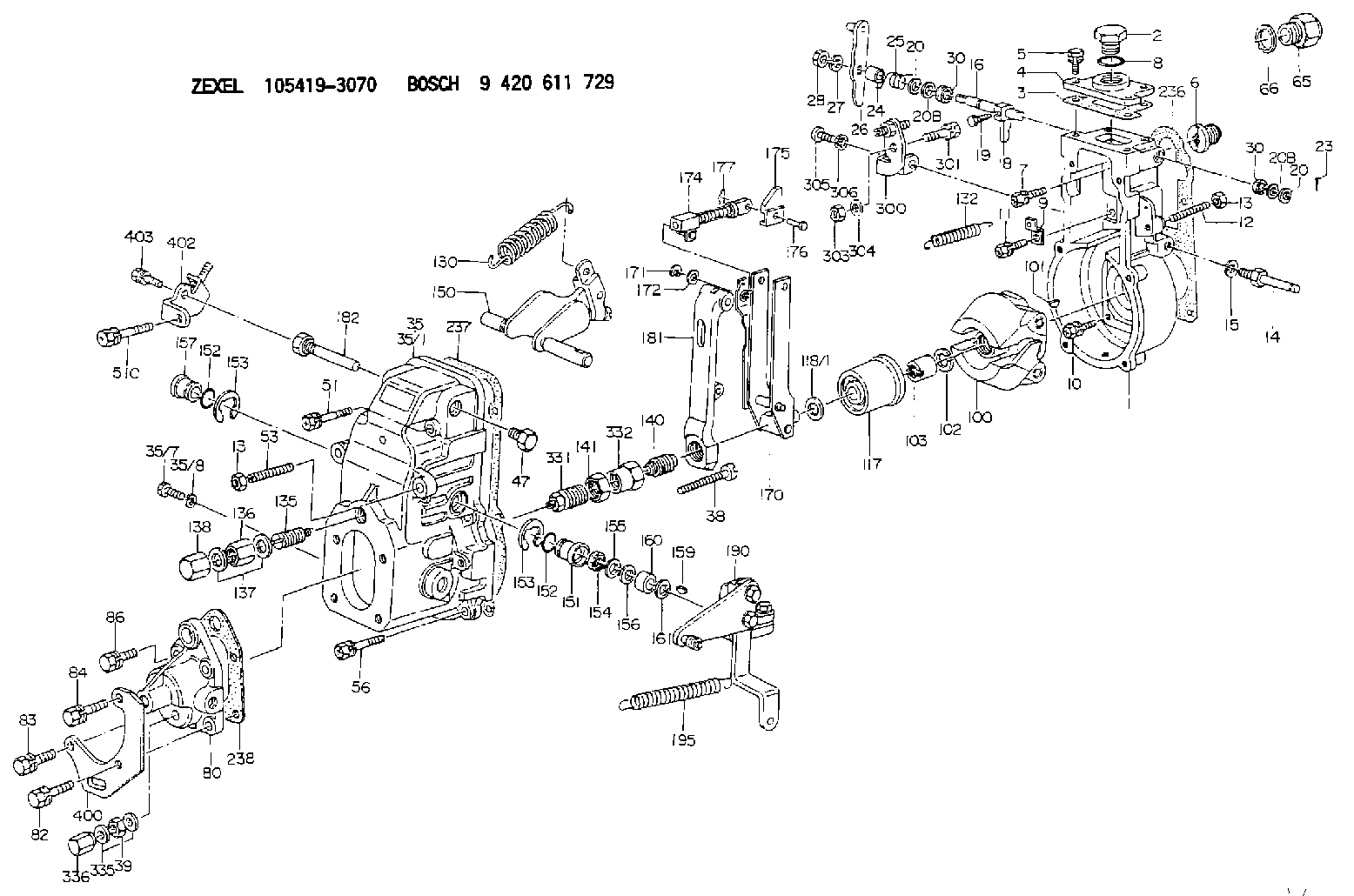
Information governor cover
BOSCH
9 421 616 413
9421616413
ZEXEL
154501-1100
1545011100

Rating:
Compare Prices: .
As an associate, we earn commssions on qualifying purchases through the links below

$663.77
02 May 2019
Parts Expr: Parts Express
COVER FOR MITSUBISHI: 1545011100
MITSUBISHI || All Brand new & rebuilt items comes with 1 year warranty. || COVER FOR MITSUBISHI: Â FORKLIFT. MB1545011100 MB1545011100 MITSUBISHI 1545011100 MB 1545011100 1545011100 MITSUBISHI1545011100 Â Â Â Â Â Â THIS PART IS ALSO LISTED UNDER THE FOLLOWING PART NUMBERS:
MITSUBISHI || All Brand new & rebuilt items comes with 1 year warranty. || COVER FOR MITSUBISHI: Â FORKLIFT. MB1545011100 MB1545011100 MITSUBISHI 1545011100 MB 1545011100 1545011100 MITSUBISHI1545011100 Â Â Â Â Â Â THIS PART IS ALSO LISTED UNDER THE FOLLOWING PART NUMBERS:
Include in ###:
Cross reference number
Zexel num
Bosch num
Firm num
Name
154501-1100
9 421 616 413
GOVERNOR COVER
C 14GJ COVER;GOV. GOV
C 14GJ COVER;GOV. GOV
Information:
37. Remove races (70) and (72) and bearing (71) from the camshaft in the fuel injection pump housing. Assemble Governor
1. Put the fuel injection pump housing in position on tool (A). Install race (3), bearing (2) and race (1) on the end of the camshaft in the fuel injection pump housing. 2. Put flyweights (5) in position on carrier assembly (4), and install dowels (6) to hold the flyweights in place. The flyweights must move freely on the dowels and have 0.010 to 0.230 mm (.0004 to .0090 in) end play. 3. Install governor shaft (7) on carrier assembly (4). 4. Install dowel (8) in governor shaft (7), and slide carrier assembly (4) down on the governor shaft until dowel (8) fits into the slot in the carrier assembly.5. Install carrier assembly (4) on the end of the camshaft. 6. Install race (12), bearing (11), race (10) and ring (9) on riser (13). 7. Install riser (13) and spring (14), if equipped, on the governor shaft. 8. Install spool (18) and ring (19) on seat (17), and use tool (B) to install ring (20) to hold them in position.9. Install seat (17) on spring (16) and spring (16) on shield (15). 10. Install dashpot assembly (21) on the governor shaft. 11. Install ring (22) in the groove on the governor shaft. Install sleeve (23), spring (25), the sleeve and bearing (24) on the governor shaft. 12. Use tool (C) to hold spring (25) under compression, and install the ring in the groove on the governor shaft. 13. Install O-ring seal (26) on sleeve (27). Install piston (29) and sleeve (27) in the governor servo as shown.14. Install valve (28) in the governor servo as shown. 15. Install lockring (33) in the groove near the center of valve (28). Put sleeve (34), spring (broken link spring) (35) and seat (36) in position on valve (28), and install lockring (37) to hold them in place. 16. Put governor servo (30) in position on the fuel injection pump housing with piston (29) engaged over the rack. Make sure the lever is engaged in the (slot) groove of riser (13). 17. If dowel (43) was removed, install it in block (44) 31 0.5 mm (1.22 .02 in) above the outside surface of the block.18. Install bolt (45) in block (44) and spring (38) on bolt (45).19. Install stop screw (40) and the locknut on collar (42). Install power setting screw (41) and the locknut on the collar.20. Install collar (42) on bolt (45). Make an alignment of the hole in the collar with the notch in bolt (45), and install bolt (39). 21. If the dowels that align block (44) with the front governor housing were removed, install them 4.0 0.5 mm (.16 .02 in) above the outside surface of the front governor housing.22. Put block (44) in position on the front governor housing with the holes in the block in alignment with dowels in the front governor
1. Put the fuel injection pump housing in position on tool (A). Install race (3), bearing (2) and race (1) on the end of the camshaft in the fuel injection pump housing. 2. Put flyweights (5) in position on carrier assembly (4), and install dowels (6) to hold the flyweights in place. The flyweights must move freely on the dowels and have 0.010 to 0.230 mm (.0004 to .0090 in) end play. 3. Install governor shaft (7) on carrier assembly (4). 4. Install dowel (8) in governor shaft (7), and slide carrier assembly (4) down on the governor shaft until dowel (8) fits into the slot in the carrier assembly.5. Install carrier assembly (4) on the end of the camshaft. 6. Install race (12), bearing (11), race (10) and ring (9) on riser (13). 7. Install riser (13) and spring (14), if equipped, on the governor shaft. 8. Install spool (18) and ring (19) on seat (17), and use tool (B) to install ring (20) to hold them in position.9. Install seat (17) on spring (16) and spring (16) on shield (15). 10. Install dashpot assembly (21) on the governor shaft. 11. Install ring (22) in the groove on the governor shaft. Install sleeve (23), spring (25), the sleeve and bearing (24) on the governor shaft. 12. Use tool (C) to hold spring (25) under compression, and install the ring in the groove on the governor shaft. 13. Install O-ring seal (26) on sleeve (27). Install piston (29) and sleeve (27) in the governor servo as shown.14. Install valve (28) in the governor servo as shown. 15. Install lockring (33) in the groove near the center of valve (28). Put sleeve (34), spring (broken link spring) (35) and seat (36) in position on valve (28), and install lockring (37) to hold them in place. 16. Put governor servo (30) in position on the fuel injection pump housing with piston (29) engaged over the rack. Make sure the lever is engaged in the (slot) groove of riser (13). 17. If dowel (43) was removed, install it in block (44) 31 0.5 mm (1.22 .02 in) above the outside surface of the block.18. Install bolt (45) in block (44) and spring (38) on bolt (45).19. Install stop screw (40) and the locknut on collar (42). Install power setting screw (41) and the locknut on the collar.20. Install collar (42) on bolt (45). Make an alignment of the hole in the collar with the notch in bolt (45), and install bolt (39). 21. If the dowels that align block (44) with the front governor housing were removed, install them 4.0 0.5 mm (.16 .02 in) above the outside surface of the front governor housing.22. Put block (44) in position on the front governor housing with the holes in the block in alignment with dowels in the front governor
Have questions with 154501-1100?
Group cross 154501-1100 ZEXEL
154501-1100
9 421 616 413
GOVERNOR COVER