Information governor ; electric
BOSCH
9 461 620 443
9461620443
ZEXEL
148530-0720
1485300720

Rating:
Include in ###:
Cross reference number
Zexel num
Bosch num
Firm num
Name
Information:
37. Remove dowels (72) and flyweights (73) from the carrier assembly.38. Remove dowel (71) from the governor shaft, and remove the governor shaft from the carrier assembly. 39. Remove races (74) and (76) and bearing (75) from the camshaft in the fuel injection pump housing.Assemble Governor
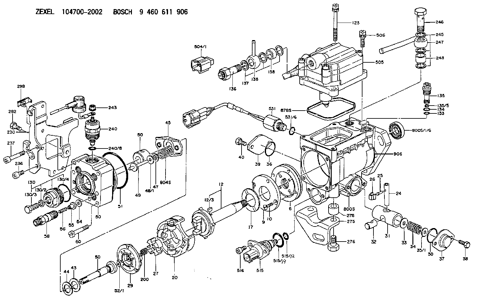
1. Put the fuel injection pump housing in position on tool (A). Install race (76) bearing (75) and race (74) on the end of the camshaft in the fuel injection pump housing. 2. Put flyweights (73) in position on carrier assembly (70), and install dowels (72) to hold the flyweights in place. The flyweights must move freely on the dowels and have 0.010 to 0.230 mm (.0004 to .0090 in.) end play. 3. Install governor shaft (77) on carrier assembly (70). 4. Install dowel (71) in governor shaft (77) and slide carrier assembly (70) down on the governor shaft until dowel (71) fits into the slot in the carrier assembly.5. Install carrier assembly (70) on the end of the camshaft. 6. Install race (68), bearing (69), race (68) and ring (67) on riser (65). 7. Install riser (65) and spring (66), if equipped, on the governor shaft. 8. Install spool (62) and ring (63) on seat (61) and use tool (B) to install ring (64) to hold them in position.9. Install seat (61) on spring (60). Install spring (60) on shield (59). 10. Install dashpot assembly (58) on the governor shaft. 11. Install ring (57) in the groove on the governor shaft. Install sleeve (78), spring (55), the sleeve and bearing (56) on the governor shaft. 12. Use tool (C) to hold spring (55) under compression, and install the ring in the groove on the governor shaft. 13. Put lever (52) in position on governor servo (53), and install pin (51) to hold the lever in place. Use a hammer and chisel to move the metal (stake) four places 90° apart on the outside surface on both legs of the governor servo to hold pin (51) in place.14. Install O-ring seal (54) on sleeve (48). Install piston (50) and sleeve (48) in the governor servo as shown.15. Install valve (49) in the governor servo as shown. 16. Install lockring (42) in the groove near the center of valve (43). Put sleeve (44), spring (broken link spring) (45) and seat (46) in position on valve (43), and install lockring (47) to hold them in place. 17. Put governor servo (41) in position on the fuel injection pump housing with piston (50) engaged over the rack. Make sure the lever is engaged in the (slot) groove of riser (65). 18. If dowel (82) was removed, install it in block (83) 31 0.5 mm (1.22 .02 in.) above the outside surface of the block.19. Install bolt (40) in block (83) and spring (38) on bolt (40).20. Install stop screw (80) and the locknut on collar (39). Install power setting screw (81) and the locknut on the collar.21. Install collar (39) on bolt (40). Make
1. Put the fuel injection pump housing in position on tool (A). Install race (76) bearing (75) and race (74) on the end of the camshaft in the fuel injection pump housing. 2. Put flyweights (73) in position on carrier assembly (70), and install dowels (72) to hold the flyweights in place. The flyweights must move freely on the dowels and have 0.010 to 0.230 mm (.0004 to .0090 in.) end play. 3. Install governor shaft (77) on carrier assembly (70). 4. Install dowel (71) in governor shaft (77) and slide carrier assembly (70) down on the governor shaft until dowel (71) fits into the slot in the carrier assembly.5. Install carrier assembly (70) on the end of the camshaft. 6. Install race (68), bearing (69), race (68) and ring (67) on riser (65). 7. Install riser (65) and spring (66), if equipped, on the governor shaft. 8. Install spool (62) and ring (63) on seat (61) and use tool (B) to install ring (64) to hold them in position.9. Install seat (61) on spring (60). Install spring (60) on shield (59). 10. Install dashpot assembly (58) on the governor shaft. 11. Install ring (57) in the groove on the governor shaft. Install sleeve (78), spring (55), the sleeve and bearing (56) on the governor shaft. 12. Use tool (C) to hold spring (55) under compression, and install the ring in the groove on the governor shaft. 13. Put lever (52) in position on governor servo (53), and install pin (51) to hold the lever in place. Use a hammer and chisel to move the metal (stake) four places 90° apart on the outside surface on both legs of the governor servo to hold pin (51) in place.14. Install O-ring seal (54) on sleeve (48). Install piston (50) and sleeve (48) in the governor servo as shown.15. Install valve (49) in the governor servo as shown. 16. Install lockring (42) in the groove near the center of valve (43). Put sleeve (44), spring (broken link spring) (45) and seat (46) in position on valve (43), and install lockring (47) to hold them in place. 17. Put governor servo (41) in position on the fuel injection pump housing with piston (50) engaged over the rack. Make sure the lever is engaged in the (slot) groove of riser (65). 18. If dowel (82) was removed, install it in block (83) 31 0.5 mm (1.22 .02 in.) above the outside surface of the block.19. Install bolt (40) in block (83) and spring (38) on bolt (40).20. Install stop screw (80) and the locknut on collar (39). Install power setting screw (81) and the locknut on the collar.21. Install collar (39) on bolt (40). Make