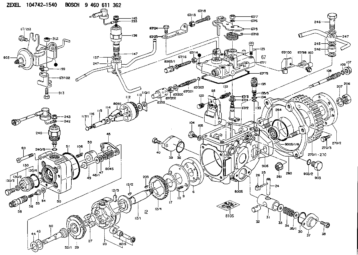
Information governor cover
BOSCH
9 461 618 600
9461618600
ZEXEL
146821-2520
1468212520

Rating:
Include in ###:
Cross reference number
Zexel num
Bosch num
Firm num
Name
146821-2520
9 461 618 600
GOVERNOR COVER
K 11FV COVER;GOV. parts(VE) Others
K 11FV COVER;GOV. parts(VE) Others
Information:
Illustration 21 shows the direction the rack moves when the fuel injector is receiving fuel.
Illustration 22 g01455811
Illustration 1 - Flowchart for the Air in Fuel Test (Test F)
Illustration 23 g01455812
Illustration 2 - Flowchart for the Air in Fuel Test (Test F)Fuel Injector Cranking Test (Test G)
Note: The fuel injector cranking test checks for worn out injectors by measuring the cranking rack.
Illustration 24 g01412134
(3) The rack control (4) The number one fuel injectorNote: Refer to Illustration 24 for the location of the rack control and the location of the number one injector.
Illustration 25 g01412115
Flowchart for the Fuel Injector Cranking Test (Test G)Fuel Shutoff Solenoid Test (Test H)
Note: The fuel shutoff solenoid test determines if the fuel shutoff solenoid and wiring harness are operating properly.
Illustration 26 g01412143
Flowchart for the Fuel Shutoff Solenoid Test (Test H)Fuel Ratio Control (FRC) Setting Test (Test I)
Note: The FRC setting test checks the FRC setting.
Illustration 27 g01412145
Flowchart for the Fuel Ratio Control (FRC) Setting Test (Test I)Governor Servo Retaining Ring Test (Test J)
Note: Do not run the engine during this test.Note: The governor servo retaining ring test checks for faulty internal parts of the governor.
Illustration 28 g01422811
(1) Paddle
Illustration 29 g01422821
(2) Clevis pin
Illustration 30 g01412147
Flowchart for the Governor Servo Retaining Ring Test (Test J)Fuel Transfer Pump Test (Test K)
Note: The fuel transfer pump test is a visual inspection of the fuel transfer pump components.
Illustration 31 g01412150
(1) Screen (2) Inlet check valve (3) Spring (4) Bolt (5) Piston (6) Outlet check valve (7) Freeze plug (8) Piston check valve (9) Passage (10) Tappet Assembly (11) CamNote: Refer to Illustration 31 for the location of the components for the fuel transfer pump.
Illustration 32 g01412149
Flowchart for the Fuel Transfer Pump Test (Test K)Fuel Ratio Control (FRC) Diaphragm Leak Test (Test L)
Note: The FRC diaphragm leak test checks for a leaking FRC diaphragm.
Illustration 33 g01412154
Flowchart for the Fuel Ratio Control (FRC) Diaphragm Leak Test (Test L)
Have questions with 146821-2520?
Group cross 146821-2520 ZEXEL
146821-2520
9 461 618 600
GOVERNOR COVER