Information governor shaft
BOSCH
9 461 610 346
9461610346
ZEXEL
146570-0100
1465700100
ISUZU
8942480020
8942480020
Rating:
Compare Prices: .
As an associate, we earn commssions on qualifying purchases through the links below

$52.00
29 Jul 2024
66.1386[29.76] pounds
ES: Auto i Center
Bosch 9461610346 Governor Shaft
BOSCH
BOSCH
Include in ###:
Cross reference number
Zexel num
Bosch num
Firm num
Name
146570-0100
9 461 610 346
8942480020 ISUZU
GOVERNOR SHAFT
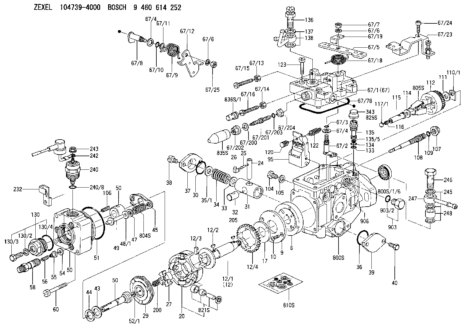
C 11FV GOVERNOR SHAFT parts(VE) Others
C 11FV GOVERNOR SHAFT parts(VE) Others
146570-0100
9 461 610 346
ME741147 MITSUBISHI
GOVERNOR SHAFT
C 11FV GOVERNOR SHAFT parts(VE) Others
C 11FV GOVERNOR SHAFT parts(VE) Others
146570-0100
9 461 610 346
1921016A00 NISSAN
GOVERNOR SHAFT
C 11FV GOVERNOR SHAFT parts(VE) Others
C 11FV GOVERNOR SHAFT parts(VE) Others
146570-0100
9 461 610 346
1921016A00 NISSAN-DIESEL
GOVERNOR SHAFT
C 11FV GOVERNOR SHAFT parts(VE) Others
C 11FV GOVERNOR SHAFT parts(VE) Others
146570-0100
9 461 610 346
145624222 MAZDA
GOVERNOR SHAFT
C 11FV GOVERNOR SHAFT parts(VE) Others
C 11FV GOVERNOR SHAFT parts(VE) Others
Information:
Cylinder Head And Valve Components
Check cylinder head for cracks before reconditioning.Flatness of the cylinder head should be within .006 in. (0.15 mm) total, and a maximum of .003 in. (0.08 mm) for any 6 in. (152.4 mm) span. A maximum stock removal of .010 in. (0.25 mm) is permissible when resurfacing the head.Always check the thickness of a cylinder head before resurfacing. The cylinder head may have been resurfaced before and would not have enough stock to be resurfaced again.To check the thickness of a cylinder head, measure through the fuel injection nozzle holes at each end of the cylinder head. For the correct thickness of the cylinder head, see the topic CYLINDER HEAD in the SPECIFICATIONS.The exhaust valve seats have replaceable inserts. To remove, use the 8S7170 Valve Seat Insert Puller Group.
REMOVING EXHAUST VALVE SEAT INSERTFreeze the exhaust valve seat inserts or use the 8S7170 Valve Seat Insert Puller Group to install inserts into head. Be sure bores are clean, free of burrs, and the insert has a good press fit into the bore.After inserts are installed, grind the seat face of the insert to be sure it is flat, has the correct angle, and is in alignment with the bore in the valve guide. For specifications, see VALVE GRINDING SPECIFICATIONS CHART. Replace exhaust valve seat inserts when valve seat width or valve head-to-cylinder head face can not be machined to the correct specification. For specifications, see VALVE GRINDING SPECIFICATIONS CHART.A 2N8943 Valve Seat Insert for the intake valve is available. This insert can be used in the repair of cylinder heads which have an intake valve seat with damage. Before, damage to an intake valve seat made replacement of the cylinder head assembly necessary.To use a 2N8943 Valve Seat Insert, the inlet port of the cylinder head must be machined to a diameter of 2.1470 .0005 in. (54.534 0.013 mm) and to a depth of .442 .002 in. (11.23 0.05 mm).To install a 2N8943 Valve Seat Insert into the cylinder head, freeze the insert or use a 2P2343 Extractor with the 8S7170 Valve Seat Insert Puller Group. After an insert is installed, grind the seat face of the insert to be sure it is flat, has the correct angle, and is in alignment with the bore in the valve guide. For specifications, see VALVE GRINDING SPECIFICATIONS CHART.Clean valve guides of all carbon and oil, using the 5P5176 Brush and a solvent.The valve guides are cast in the cylinder heads. Check each valve guide bore size 3/4 in. (19.1 mm) deep from each end. The bore size is .3745 .0005 in. (9.512 0.013 mm) and the maximum size worn is .3760 in. (9.550 mm). Valve guides worn more than the maximum wear size, can be restored to original tolerances through knurling.Use the 5P3536 Valve Guide Gauge Group to check the bore of the valve guides. Special Instructions GMG02562 gives complete and detailed instructions for use of the 5P3536 Valve Guide Gauge
Have questions with 146570-0100?
Group cross 146570-0100 ZEXEL
Isuzu
146570-0100
9 461 610 346
8942480020
GOVERNOR SHAFT
Mitsubishi
146570-0100
9 461 610 346
ME741147
GOVERNOR SHAFT
Nissan
146570-0100
9 461 610 346
1921016A00
GOVERNOR SHAFT
Nissan-Diesel
146570-0100
9 461 610 346
1921016A00
GOVERNOR SHAFT
Mazda
146570-0100
9 461 610 346
145624222
GOVERNOR SHAFT