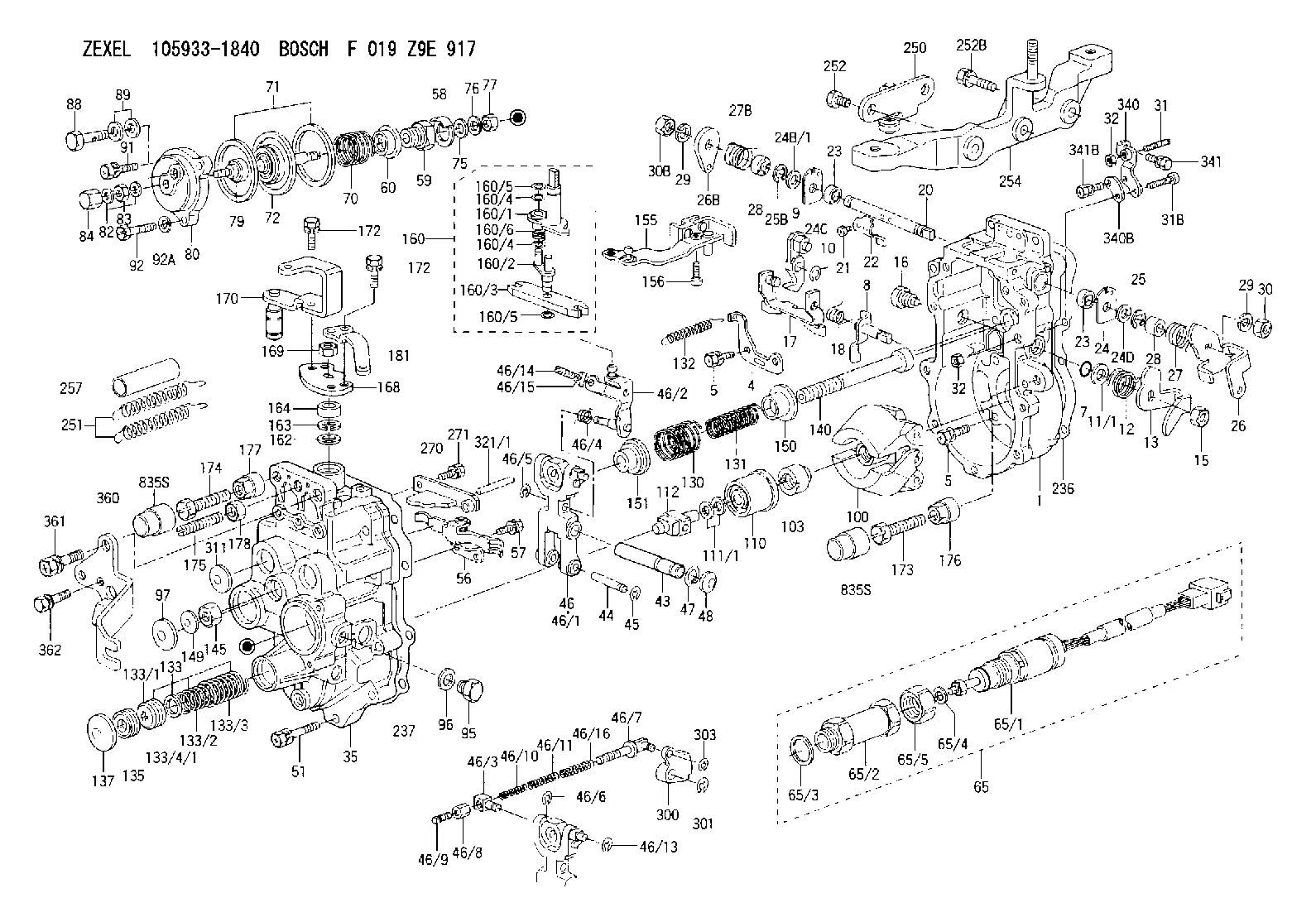
Information governor
BOSCH
F 019 Z9E 917
f019z9e917
ZEXEL
105933-1840
1059331840
Rating:
Scheme ###:
| 1. | [1] | 159360-0620 | GOVERNOR HOUSING |
| 4. | [1] | 159362-5120 | PLATE |
| 5. | [10] | 139006-6100 | BLEEDER SCREW |
| 5. | [10] | 139006-6100 | BLEEDER SCREW |
| 7. | [1] | 139709-0100 | O-RING |
| 8. | [1] | 159364-4820 | LEVER SHAFT |
| 9. | [1] | 159362-6620 | CONTROL LEVER |
| 10. | [1] | 016010-0740 | LOCKING WASHER |
| 11/1. | [0] | 029311-0220 | SHIM D18&10.3T0.2 |
| 11/1. | [0] | 029311-0230 | SHIM D18&10.3T0.5 |
| 11/1. | [0] | 029311-0430 | SHIM D18&10.3T0.30 |
| 11/1. | [0] | 029311-0440 | SHIM D18&10.3T0.40 |
| 11/1. | [0] | 029311-0450 | SHIM D18&10.3T0.25 |
| 11/1. | [0] | 029311-0460 | SHIM D18&10.3T0.35 |
| 11/1. | [0] | 139410-3300 | SHIM D18&10.3T0.6 |
| 11/1. | [0] | 139410-3400 | SHIM D18&10.3T0.8 |
| 11/1. | [0] | 139410-3500 | SHIM D18&10.3T0.9 |
| 12. | [1] | 159368-7900 | COILED SPRING |
| 13. | [1] | 159362-2500 | CONTROL LEVER |
| 15. | [1] | 013020-8040 | UNION NUT M8P1.25H7 |
| 16. | [1] | 159364-5000 | CAPSULE |
| 17. | [1] | 159362-2620 | CONTROL LEVER |
| 18. | [1] | 159215-0300 | COILED SPRING |
| 20. | [1] | 159365-4300 | LEVER SHAFT |
| 21. | [2] | 020104-1240 | BLEEDER SCREW |
| 22. | [1] | 159362-0600 | CONTROL LEVER |
| 23. | [2] | 139608-0600 | PACKING RING |
| 23. | [2] | 139608-0600 | PACKING RING |
| 24. | [1] | 159362-0700 | PLAIN WASHER |
| 24B/1. | [0] | 139408-1000 | SHIM D16&8T0.5 |
| 24B/1. | [0] | 139408-1300 | SHIM D16&8T0.2 |
| 24C. | [1] | 159362-0700 | PLAIN WASHER |
| 24D. | [2] | 139308-2100 | PLAIN WASHER |
| 25. | [1] | 159238-4200 | LOCKING WASHER |
| 25B. | [1] | 159238-4200 | LOCKING WASHER |
| 26. | [1] | 159390-6600 | CONTROL LEVER |
| 26B. | [1] | 159390-2900 | CONTROL LEVER |
| 27. | [1] | 159369-2000 | COILED SPRING |
| 27B. | [1] | 159368-7300 | COILED SPRING |
| 28. | [2] | 159364-6000 | BUSHING |
| 28. | [2] | 159364-6000 | BUSHING |
| 29. | [2] | 014110-8440 | LOCKING WASHER |
| 29. | [2] | 014110-8440 | LOCKING WASHER |
| 30. | [1] | 013020-8040 | UNION NUT M8P1.25H7 |
| 30B. | [1] | 013030-8040 | UNION NUT M8P1.25H5 |
| 31. | [1] | 155615-1100 | FLAT-HEAD SCREW M6P1.0L37 |
| 31B. | [1] | 153505-0800 | FLAT-HEAD SCREW |
| 32. | [2] | 013030-6040 | UNION NUT M6P1H3.6 |
| 32. | [2] | 013030-6040 | UNION NUT M6P1H3.6 |
| 35. | [1] | 159361-1020 | GOVERNOR COVER |
| 43. | [1] | 159364-0700 | LEVER SHAFT |
| 44. | [1] | 159364-0800 | BEARING PIN |
| 45. | [2] | 016010-0640 | LOCKING WASHER |
| 46. | [1] | 159362-8620 | TENSIONING LEVER |
| 46/1. | [1] | 159362-8521 | TENSIONING LEVER |
| 46/2. | [1] | 159362-8721 | GUIDE LEVER |
| 46/3. | [1] | 159364-4201 | BEARING PIN |
| 46/4. | [1] | 159368-7700 | COILED SPRING |
| 46/5. | [1] | 016010-0540 | LOCKING WASHER |
| 46/6. | [1] | 016010-0440 | LOCKING WASHER |
| 46/7. | [1] | 159364-4121 | RACK |
| 46/8. | [1] | 159364-4300 | UNION NUT |
| 46/9. | [1] | 159364-4400 | FLAT-HEAD SCREW |
| 46/10. | [1] | 159368-6900 | COILED SPRING |
| 46/11. | [1] | 159368-7000 | COILED SPRING |
| 46/13. | [1] | 016010-0540 | LOCKING WASHER |
| 46/14. | [1] | 159364-1900 | FLAT-HEAD SCREW |
| 46/15. | [1] | 159364-1800 | UNION NUT |
| 46/16. | [1] | 159368-9500 | COILED SPRING |
| 47. | [2] | 016110-1020 | LOCKING WASHER |
| 48. | [2] | 159237-0200 | CAPSULE |
| 51. | [9] | 020106-3840 | BLEEDER SCREW |
| 56. | [1] | 159362-3720 | LEVER GROUP |
| 57. | [2] | 020105-1040 | BLEEDER SCREW M5P0.8L10 |
| 58. | [1] | 146711-0000 | PLATE |
| 59. | [1] | 154413-3600 | BUSHING |
| 60. | [1] | 146716-0000 | UNION NUT |
| 65. | [1] | 154613-2220 | RACK SENSOR ASSY |
| 65/1. | [1] | 407945-0620 | RACK SENSOR |
| 65/2. | [1] | 154614-9000 | JOINT CONNECTION |
| 65/3. | [1] | 026524-3040 | GASKET |
| 65/4. | [1] | 029310-6280 | SHIM D11.5&6.4T1.50 |
| 65/5. | [1] | 154614-1900 | UNION NUT |
| 70. | [1] | 154416-7800 | COILED SPRING |
| 71. | [2] | 154413-2600 | GASKET |
| 72. | [1] | 154415-2220 | DIAPHRAGM |
| 75. | [1] | 154415-1100 | SLOTTED WASHER |
| 76. | [1] | 014110-6440 | LOCKING WASHER |
| 77. | [1] | 013030-6040 | UNION NUT M6P1H3.6 |
| 79. | [1] | 154413-4000 | FLAT-HEAD SCREW |
| 80. | [1] | 154404-5400 | COVER |
| 82. | [2] | 026506-1040 | GASKET D9.9&6.2T1 |
| 83. | [1] | 013030-6040 | UNION NUT M6P1H3.6 |
| 84. | [1] | 154035-1600 | CAP NUT |
| 88. | [1] | 029731-0180 | EYE BOLT |
| 89. | [2] | 026510-1340 | GASKET D13.4&10.2T1 |
| 91. | [1] | 020106-2040 | BLEEDER SCREW M6P1L20 |
| 92. | [2] | 139006-7000 | BLEEDER SCREW |
| 92A. | [2] | 014110-6440 | LOCKING WASHER |
| 95. | [1] | 029111-2090 | CAPSULE |
| 96. | [1] | 029331-2130 | GASKET |
| 97. | [1] | 159364-2000 | CAPSULE |
| 100. | [1] | 154101-4920 | FLYWEIGHT ASSEMBLY |
| 103. | [1] | 154101-2500 | HEXAGON NUT |
| 110. | [1] | 154123-2320 | SLIDING PIECE |
| 111/1. | [0] | 029311-0010 | SHIM D14&10.1T0.2 |
| 111/1. | [0] | 029311-0180 | SHIM D14&10.1T0.3 |
| 111/1. | [0] | 029311-0190 | SHIM D14&10.1T0.40 |
| 111/1. | [0] | 029311-0210 | SHIM D14&10.1T1 |
| 111/1. | [0] | 139410-0000 | SHIM D14.0&10.1T0.5 |
| 111/1. | [0] | 139410-0100 | SHIM D14.0&10.1T1.5 |
| 111/1. | [0] | 139410-3000 | SHIM D14&10.1T2.0 |
| 111/1. | [0] | 139410-3100 | SHIM D14&10.1T3.0 |
| 111/1. | [0] | 139410-3200 | SHIM D14&10.1T4.0 |
| 112. | [1] | 159364-2400 | TERMINAL STUD |
| 130. | [1] | 159367-2200 | GOVERNOR SPRING |
| 131. | [1] | 159367-6500 | GOVERNOR SPRING |
| 132. | [1] | 159368-6500 | COILED SPRING |
| 133. | [1] | 159368-3120 | SPRING PACK |
| 133/1. | [1] | 159364-2200 | GUIDE SLEEVE |
| 133/2. | [1] | 159368-0200 | COILED SPRING |
| 133/3. | [1] | 159368-0400 | COILED SPRING |
| 133/4/1. | [0] | 029311-0010 | SHIM D14&10.1T0.2 |
| 133/4/1. | [0] | 029311-0180 | SHIM D14&10.1T0.3 |
| 133/4/1. | [0] | 029311-0190 | SHIM D14&10.1T0.40 |
| 133/4/1. | [0] | 029311-0210 | SHIM D14&10.1T1 |
| 133/4/1. | [0] | 139410-0000 | SHIM D14.0&10.1T0.5 |
| 133/4/1. | [0] | 139410-0100 | SHIM D14.0&10.1T1.5 |
| 133/4/1. | [0] | 139410-3000 | SHIM D14&10.1T2.0 |
| 133/4/1. | [0] | 139410-3100 | SHIM D14&10.1T3.0 |
| 133/4/1. | [0] | 139410-3200 | SHIM D14&10.1T4.0 |
| 135. | [1] | 159364-2300 | FLAT-HEAD SCREW |
| 137. | [1] | 159364-2000 | CAPSULE |
| 140. | [1] | 159364-2500 | LEVER SHAFT |
| 145. | [1] | 159233-5700 | UNION NUT |
| 149. | [1] | 159237-5400 | CAPSULE |
| 150. | [1] | 159364-2600 | SLOTTED WASHER |
| 151. | [1] | 159364-2700 | SLOTTED WASHER |
| 155. | [1] | 159363-3620 | STRAP |
| 156. | [1] | 010235-1020 | HEX-SOCKET-HEAD CAP SCREW |
| 160. | [1] | 159362-3420 | LEVER GROUP |
| 160/1. | [1] | 159364-4920 | LEVER SHAFT |
| 160/2. | [1] | 159362-1020 | CONTROL LEVER |
| 160/3. | [1] | 159362-2000 | CONTROL LEVER |
| 160/4. | [2] | 159362-1300 | SHIM |
| 160/4. | [2] | 159362-1300 | SHIM |
| 160/5. | [2] | 016010-0840 | LOCKING WASHER |
| 160/5. | [2] | 016010-0840 | LOCKING WASHER |
| 160/6. | [1] | 159368-7400 | COILED SPRING |
| 162. | [1] | 139411-0600 | SHIM |
| 163. | [1] | 159238-3000 | LOCKING WASHER |
| 164. | [1] | 139610-0800 | PACKING RING |
| 168. | [1] | 159380-0300 | CONTROL LEVER |
| 169. | [1] | 013020-8040 | UNION NUT M8P1.25H7 |
| 170. | [1] | 159383-1420 | CONTROL LEVER |
| 172. | [4] | 020106-1240 | BLEEDER SCREW M6P1.0L12 |
| 172. | [4] | 020106-1240 | BLEEDER SCREW M6P1.0L12 |
| 173. | [1] | 154013-1700 | BLEEDER SCREW |
| 173B. | [1] | 154013-1800 | BLEEDER SCREW |
| 173C. | [1] | 154013-1900 | BLEEDER SCREW |
| 174. | [1] | 154013-2000 | BLEEDER SCREW |
| 175. | [1] | 154013-2100 | FLAT-HEAD SCREW |
| 176. | [1] | 154011-4000 | UNION NUT |
| 177. | [1] | 154011-4100 | UNION NUT |
| 178. | [1] | 013131-0040 | UNION NUT M10P1.25H6 |
| 181. | [1] | 159382-5000 | CONTROL LEVER |
| 236. | [1] | 154390-4200 | GASKET |
| 237. | [1] | 154390-2500 | GASKET |
| 250. | [1] | 159399-9620 | BRACKET |
| 251. | [2] | 154339-7800 | COILED SPRING |
| 252. | [2] | 156633-0200 | BLEEDER SCREW |
| 252B. | [1] | 156633-4700 | BLEEDER SCREW |
| 254. | [1] | 159400-2921 | BRACKET |
| 257. | [2] | 154156-0500 | TUBE |
| 270. | [1] | 159362-6920 | GUIDE PLATE |
| 271. | [2] | 020106-1640 | BLEEDER SCREW M6P1.0L14 |
| 300. | [1] | 159377-3400 | CAM PLATE |
| 301. | [1] | 016010-0840 | LOCKING WASHER |
| 303. | [1] | 016010-0540 | LOCKING WASHER |
| 311. | [2] | 159237-5400 | CAPSULE |
| 321/1. | [1] | 159274-5100 | STOP PIN L72.5 |
| 321/1. | [1] | 159274-5200 | STOP PIN L73 |
| 321/1. | [1] | 159274-5300 | STOP PIN L73.5 |
| 321/1. | [1] | 159274-5400 | STOP PIN L74 |
| 321/1. | [1] | 159274-5500 | STOP PIN L74.5 |
| 321/1. | [1] | 159274-5600 | STOP PIN L75 |
| 321/1. | [1] | 159274-5700 | STOP PIN L75.5 |
| 321/1. | [1] | 159274-5800 | STOP PIN L76 |
| 321/1. | [1] | 159274-5900 | STOP PIN L76.5 |
| 321/1. | [1] | 159274-6000 | STOP PIN L77 |
| 321/1. | [1] | 159274-6100 | STOP PIN L77.5 |
| 321/1. | [1] | 159274-6200 | STOP PIN L78 |
| 321/1. | [1] | 159274-6300 | STOP PIN L78.5 |
| 321/1. | [1] | 159274-6400 | STOP PIN L79 |
| 321/1. | [1] | 159274-6500 | STOP PIN L79.5 |
| 321/1. | [1] | 159274-6600 | STOP PIN L80 |
| 321/1. | [1] | 159274-6700 | STOP PIN L80.5 |
| 321/1. | [1] | 159274-6800 | STOP PIN L81 |
| 321/1. | [1] | 159274-6900 | STOP PIN L81.5 |
| 321/1. | [1] | 159274-7000 | STOP PIN L82 |
| 321/1. | [1] | 159274-7100 | STOP PIN L82.5 |
| 321/1. | [1] | 159274-7200 | STOP PIN L83 |
| 321/1. | [1] | 159274-7300 | STOP PIN L83.5 |
| 321/1. | [1] | 159274-7400 | STOP PIN L84 |
| 321/1. | [1] | 159274-7500 | STOP PIN L84.5 |
| 321/1. | [1] | 159274-7600 | STOP PIN L85 |
| 321/1. | [1] | 159274-7700 | STOP PIN L85.5 |
| 321/1. | [1] | 159274-7800 | STOP PIN L86 |
| 321/1. | [1] | 159274-7900 | STOP PIN L86.5 |
| 321/1. | [1] | 159274-8000 | STOP PIN L87 |
| 321/1. | [1] | 159274-8100 | STOP PIN L87.5 |
| 321/1. | [1] | 159274-8200 | STOP PIN L88 |
| 321/1. | [1] | 159274-8300 | STOP PIN L88.5 |
| 321/1. | [1] | 159274-8400 | STOP PIN L89 |
| 321/1. | [1] | 159274-8500 | STOP PIN L89.5 |
| 321/1. | [1] | 159274-8600 | STOP PIN L90 |
| 340. | [1] | 159397-0420 | BRACKET |
| 340B. | [1] | 159397-0500 | PLATE |
| 341. | [1] | 020106-1240 | BLEEDER SCREW M6P1.0L12 |
| 341B. | [1] | 020106-1840 | BLEEDER SCREW M6P1L18 |
| 360. | [1] | 159398-8820 | BRACKET |
| 361. | [1] | 010110-2040 | BLEEDER SCREW M10P1.25L20 |
| 362. | [2] | 020106-1440 | BLEEDER SCREW M6P1.0L14 |
| 835S. | [2] | 154062-1700 | CAP D20L32 |
| 835S. | [2] | 154062-1700 | CAP D20L32 |
Include in #1:
107691-3701
as GOVERNOR
Cross reference number
Zexel num
Bosch num
Firm num
Name
105933-1840
GOVERNOR
K 14JG MECHANICAL GOVERNOR GOV RLD-J(TICS) GOV
K 14JG MECHANICAL GOVERNOR GOV RLD-J(TICS) GOV
105933-1840
S224002430A HINO
GOVERNOR
A K 14JG MECHANICAL GOVERNOR GOV RLD-J(TICS) GOV
A K 14JG MECHANICAL GOVERNOR GOV RLD-J(TICS) GOV
Information:
Caterpillar: Confidential Yellow
PSP FOR THE USE OF TWO CLAMPS TO HOLD THE BODY AND FUEL NOZZLE IN POSITION ON 3406, 3408 AND 3412 ENGINES - MAILED WORLDWIDE EXC EPT CANADA, BRAZIL & CACO
The information supplied in this service letter may not be valid after the termination date of this program. Do not perform the work outlined in this Service Letter after the termination date without first contacting your Caterpillar product analyst.
PRODUCT SUPPORT PROGRAM FOR THE USE OF TWO CLAMPS TO HOLD THE BODY AND FUEL NOZZLE IN POSITION ON 3406, 3408 AND 3412 ENGINES, 1252, PS4019 U-74 AU-59 E-47 O-45 TT-12 TA-6 TM-6 This Program can be administered either before or after a failure. In either case the warranty allowances will be the same and contingent damage will not be allowed. The decision whether to apply the Program is made by the dealer. When reporting the repair use "PS4019" as Part Number and "7755" as Group Number. Although products in the field are to be administered as described above, dealers should rework parts stock immediately. Termination Date
September 30, 1986.
Problem
Engines equipped with 4W5719 (3406) or 4W5733 (3408, 3412) Adapter Assemblies use one 4W5717 Clamp to hold the body and fuel nozzle in position. See the Illustration. These adapter assemblies are also used in 0R0977 (3406) 0R0980 (3408) and 0R2659 (3412) Remanufactured Head Assemblies. One clamp does not provide enough force to hold the body and fuel nozzle tight. This permits fuel to leak past the internal parts of the nozzle and cause the nozzle case to bulge or split. This program provides for an additional clamp and bolts to be used with these adapter assemblies. (SEE ILLUSTRATION)
Affected Product
1/850907/01/002
Parts Needed
1-4W5717 Clamp and 2-5P6900 Bolts for each adapter assembly.
Action Required
The new parts should be installed on cylinder heads in parts stock immediately. Only cylinder heads received before this Service Letter need to be checked. The new parts should be installed on products in the field only when the valve cover has been removed for some other repair or inspection. Install the new clamp and bolts 180 deg. from the existing clamp and bolts. Tighten the bolts for the new clamp to 31 +/- 7 N X m (23 +/- 5 lb ft). Check to make sure the bolts for the existing clamp are tightened to the same torque. Then check the torque on the bolts for the new clamp. (SEE ILLUSTRATION)
Parts Disposition
Not applicable.