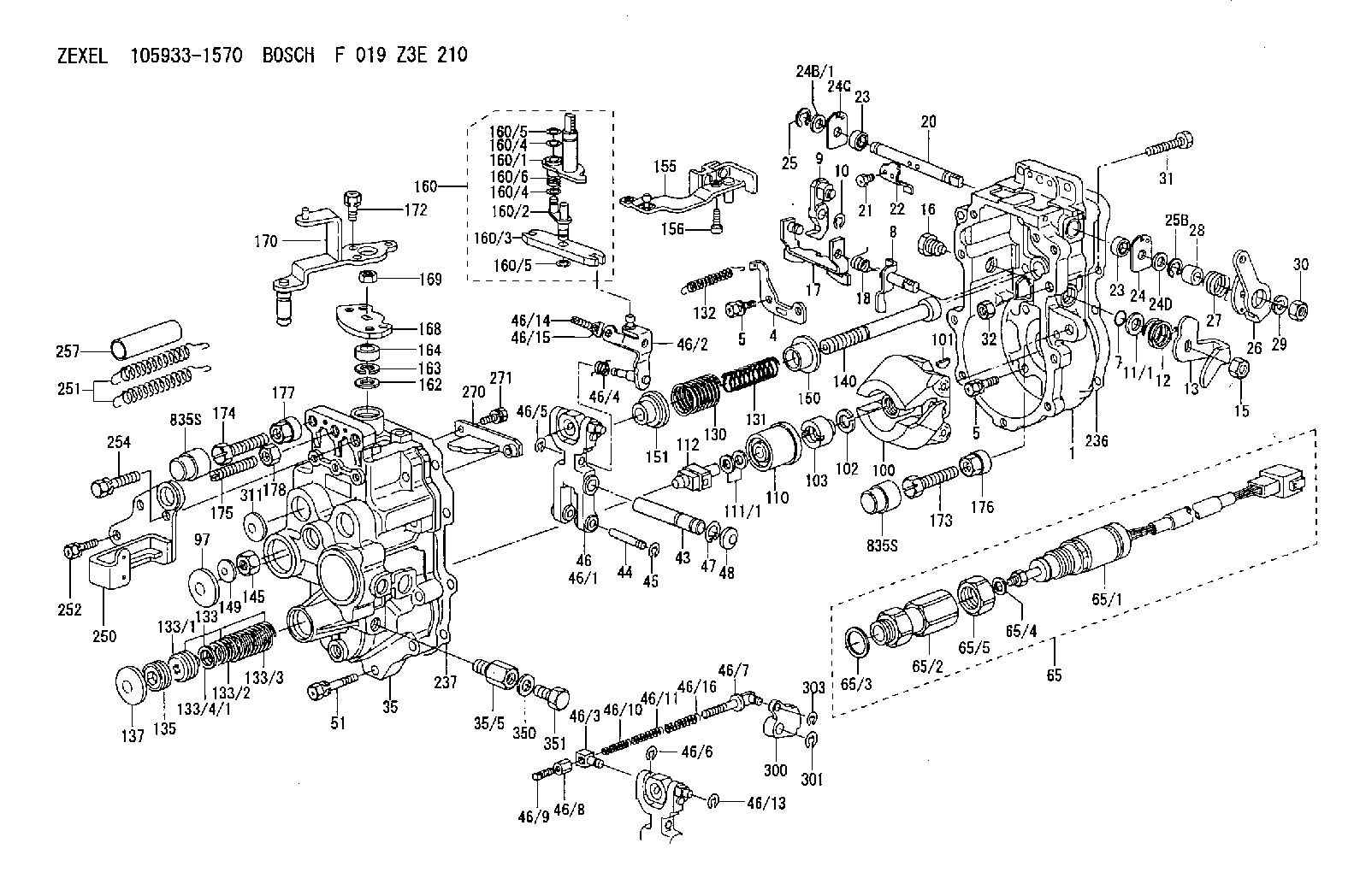
Information governor
BOSCH
F 019 Z3E 210
f019z3e210
ZEXEL
105933-1570
1059331570
ISUZU
1157901460
1157901460

Rating:
Scheme ###:
| 1. | [1] | 159360-0620 | GOVERNOR HOUSING |
| 4. | [1] | 159362-5120 | PLATE |
| 5. | [10] | 139006-6100 | BLEEDER SCREW |
| 5. | [10] | 139006-6100 | BLEEDER SCREW |
| 7. | [1] | 139709-0100 | O-RING |
| 8. | [1] | 159364-4820 | LEVER SHAFT |
| 9. | [1] | 159362-6620 | CONTROL LEVER |
| 10. | [1] | 016010-0740 | LOCKING WASHER |
| 11/1. | [0] | 029311-0220 | SHIM D18&10.3T0.2 |
| 11/1. | [0] | 029311-0230 | SHIM D18&10.3T0.5 |
| 11/1. | [0] | 029311-0430 | SHIM D18&10.3T0.30 |
| 11/1. | [0] | 029311-0440 | SHIM D18&10.3T0.40 |
| 11/1. | [0] | 029311-0450 | SHIM D18&10.3T0.25 |
| 11/1. | [0] | 029311-0460 | SHIM D18&10.3T0.35 |
| 11/1. | [0] | 139410-3300 | SHIM D18&10.3T0.6 |
| 11/1. | [0] | 139410-3400 | SHIM D18&10.3T0.8 |
| 11/1. | [0] | 139410-3500 | SHIM D18&10.3T0.9 |
| 12. | [1] | 159368-7900 | COILED SPRING |
| 13. | [1] | 159362-2500 | CONTROL LEVER |
| 15. | [1] | 013020-8040 | UNION NUT M8P1.25H7 |
| 16. | [1] | 159364-5000 | CAPSULE |
| 17. | [1] | 159362-2620 | CONTROL LEVER |
| 18. | [1] | 159215-0300 | COILED SPRING |
| 20. | [1] | 159364-9800 | LEVER SHAFT |
| 21. | [2] | 020104-1240 | BLEEDER SCREW |
| 22. | [1] | 159362-0600 | CONTROL LEVER |
| 23. | [2] | 139608-0600 | PACKING RING |
| 23. | [2] | 139608-0600 | PACKING RING |
| 24. | [1] | 159362-0700 | PLAIN WASHER |
| 24B/1. | [0] | 139408-1000 | SHIM D16&8T0.5 |
| 24B/1. | [0] | 139408-1300 | SHIM D16&8T0.2 |
| 24C. | [1] | 159362-0700 | PLAIN WASHER |
| 24D. | [1] | 139308-2100 | PLAIN WASHER |
| 25. | [1] | 159238-4200 | LOCKING WASHER |
| 25B. | [1] | 159238-4200 | LOCKING WASHER |
| 26. | [1] | 159391-1520 | CONTROL LEVER |
| 27. | [1] | 159368-6100 | COILED SPRING |
| 28. | [1] | 159364-6000 | BUSHING |
| 29. | [1] | 014110-8440 | LOCKING WASHER |
| 30. | [1] | 013020-8040 | UNION NUT M8P1.25H7 |
| 31. | [1] | 153141-3200 | FLAT-HEAD SCREW |
| 32. | [1] | 013030-6040 | UNION NUT M6P1H3.6 |
| 35. | [1] | 159361-2720 | GOVERNOR COVER |
| 35/5. | [1] | 159364-4000 | ADAPTOR |
| 43. | [1] | 159364-0700 | LEVER SHAFT |
| 44. | [1] | 159364-0800 | BEARING PIN |
| 45. | [2] | 016010-0640 | LOCKING WASHER |
| 46. | [1] | 159362-8620 | TENSIONING LEVER |
| 46/1. | [1] | 159362-8521 | TENSIONING LEVER |
| 46/2. | [1] | 159362-8721 | GUIDE LEVER |
| 46/3. | [1] | 159364-4201 | BEARING PIN |
| 46/4. | [1] | 159368-7700 | COILED SPRING |
| 46/5. | [1] | 016010-0540 | LOCKING WASHER |
| 46/6. | [1] | 016010-0440 | LOCKING WASHER |
| 46/7. | [1] | 159364-4121 | RACK |
| 46/8. | [1] | 159364-4300 | UNION NUT |
| 46/9. | [1] | 159364-4400 | FLAT-HEAD SCREW |
| 46/10. | [1] | 159368-6900 | COILED SPRING |
| 46/11. | [1] | 159368-7000 | COILED SPRING |
| 46/13. | [1] | 016010-0540 | LOCKING WASHER |
| 46/14. | [1] | 159364-1900 | FLAT-HEAD SCREW |
| 46/15. | [1] | 159364-1800 | UNION NUT |
| 46/16. | [1] | 159368-9500 | COILED SPRING |
| 47. | [2] | 016110-1020 | LOCKING WASHER |
| 48. | [2] | 159237-0200 | CAPSULE |
| 51. | [9] | 020106-3840 | BLEEDER SCREW |
| 65. | [1] | 154612-6820 | RACK SENSOR ASSY |
| 65/1. | [1] | 407945-0350 | RACK SENSOR |
| 65/2. | [1] | 154614-8300 | JOINT CONNECTION |
| 65/3. | [1] | 026524-3040 | GASKET |
| 65/4. | [1] | 029310-6280 | SHIM D11.5&6.4T1.50 |
| 65/5. | [1] | 154614-1900 | UNION NUT |
| 97. | [1] | 159364-2000 | CAPSULE |
| 100. | [1] | 154101-1020 | FLYWEIGHT ASSEMBLY |
| 101. | [1] | 025803-1310 | WOODRUFF KEY |
| 102. | [1] | 029321-2020 | LOCKING WASHER |
| 103. | [1] | 029231-2030 | UNION NUT |
| 110. | [1] | 154123-2320 | SLIDING PIECE |
| 111/1. | [0] | 029311-0010 | SHIM D14&10.1T0.2 |
| 111/1. | [0] | 029311-0180 | SHIM D14&10.1T0.3 |
| 111/1. | [0] | 029311-0190 | SHIM D14&10.1T0.40 |
| 111/1. | [0] | 029311-0210 | SHIM D14&10.1T1 |
| 111/1. | [0] | 139410-0000 | SHIM D14.0&10.1T0.5 |
| 111/1. | [0] | 139410-0100 | SHIM D14.0&10.1T1.5 |
| 111/1. | [0] | 139410-3000 | SHIM D14&10.1T2.0 |
| 111/1. | [0] | 139410-3100 | SHIM D14&10.1T3.0 |
| 111/1. | [0] | 139410-3200 | SHIM D14&10.1T4.0 |
| 112. | [1] | 159364-2100 | TERMINAL STUD |
| 130. | [1] | 159367-1000 | GOVERNOR SPRING |
| 131. | [1] | 159367-6700 | GOVERNOR SPRING |
| 132. | [1] | 159368-6500 | COILED SPRING |
| 133. | [1] | 159368-2320 | SPRING PACK |
| 133/1. | [1] | 159364-2200 | GUIDE SLEEVE |
| 133/2. | [1] | 159368-0200 | COILED SPRING |
| 133/3. | [1] | 159368-0500 | COILED SPRING |
| 133/4/1. | [0] | 029311-0010 | SHIM D14&10.1T0.2 |
| 133/4/1. | [0] | 029311-0180 | SHIM D14&10.1T0.3 |
| 133/4/1. | [0] | 029311-0190 | SHIM D14&10.1T0.40 |
| 133/4/1. | [0] | 029311-0210 | SHIM D14&10.1T1 |
| 133/4/1. | [0] | 139410-0000 | SHIM D14.0&10.1T0.5 |
| 133/4/1. | [0] | 139410-0100 | SHIM D14.0&10.1T1.5 |
| 133/4/1. | [0] | 139410-3000 | SHIM D14&10.1T2.0 |
| 133/4/1. | [0] | 139410-3100 | SHIM D14&10.1T3.0 |
| 133/4/1. | [0] | 139410-3200 | SHIM D14&10.1T4.0 |
| 135. | [1] | 159364-2300 | FLAT-HEAD SCREW |
| 137. | [1] | 159364-2000 | CAPSULE |
| 140. | [1] | 159364-2500 | LEVER SHAFT |
| 145. | [1] | 159233-5700 | UNION NUT |
| 149. | [1] | 159237-5400 | CAPSULE |
| 150. | [1] | 159364-2600 | SLOTTED WASHER |
| 151. | [1] | 159364-2700 | SLOTTED WASHER |
| 155. | [1] | 159363-3720 | STRAP |
| 156. | [1] | 010235-1020 | HEX-SOCKET-HEAD CAP SCREW |
| 160. | [1] | 159362-3420 | LEVER GROUP |
| 160/1. | [1] | 159364-4920 | LEVER SHAFT |
| 160/2. | [1] | 159362-1020 | CONTROL LEVER |
| 160/3. | [1] | 159362-2000 | CONTROL LEVER |
| 160/4. | [2] | 159362-1300 | SHIM |
| 160/4. | [2] | 159362-1300 | SHIM |
| 160/5. | [2] | 016010-0840 | LOCKING WASHER |
| 160/5. | [2] | 016010-0840 | LOCKING WASHER |
| 160/6. | [1] | 159368-7400 | COILED SPRING |
| 162. | [1] | 139411-0600 | SHIM |
| 163. | [1] | 159238-3000 | LOCKING WASHER |
| 164. | [1] | 139610-0800 | PACKING RING |
| 168. | [1] | 159380-0300 | CONTROL LEVER |
| 169. | [1] | 013020-8040 | UNION NUT M8P1.25H7 |
| 170. | [1] | 159383-2120 | CONTROL LEVER |
| 172. | [3] | 020106-1240 | BLEEDER SCREW M6P1.0L12 |
| 173. | [1] | 154013-1700 | BLEEDER SCREW M8P1.25L45 |
| 173B. | [1] | 154013-1800 | BLEEDER SCREW M8P1.25L49 |
| 173C. | [1] | 154013-1900 | BLEEDER SCREW M8P1.25L53 |
| 174. | [1] | 154013-2000 | BLEEDER SCREW |
| 175. | [1] | 154013-2800 | FLAT-HEAD SCREW |
| 176. | [1] | 154011-4000 | UNION NUT |
| 177. | [1] | 154011-4100 | UNION NUT |
| 178. | [1] | 013131-0040 | UNION NUT M10P1.25H6 |
| 236. | [1] | 154390-4200 | GASKET |
| 237. | [1] | 154390-2500 | GASKET |
| 250. | [1] | 159400-0920 | BRACKET |
| 251. | [2] | 154339-8200 | COILED SPRING |
| 252. | [2] | 020106-1440 | BLEEDER SCREW M6P1.0L14 |
| 254. | [1] | 010110-2040 | BLEEDER SCREW M10P1.25L20 |
| 257. | [2] | 154156-0600 | TUBE |
| 270. | [1] | 159362-4420 | GUIDE PLATE |
| 271. | [2] | 020106-1640 | BLEEDER SCREW M6P1.0L14 |
| 300. | [1] | 159377-1000 | CAM PLATE |
| 301. | [1] | 016010-0840 | LOCKING WASHER |
| 303. | [1] | 016010-0540 | LOCKING WASHER |
| 311. | [2] | 159237-5400 | CAPSULE |
| 350. | [1] | 139512-0000 | GASKET D17.2&12.2T1.0 |
| 351. | [1] | 159395-5200 | CAPSULE |
| 835S. | [2] | 154062-1700 | CAP D20L32 |
| 835S. | [2] | 154062-1700 | CAP D20L32 |
Include in #1:
107692-1660
as GOVERNOR
Cross reference number
Zexel num
Bosch num
Firm num
Name
Information:
Governor Linkage Adjustment
(1) Rod. (2) Nut. (3) Control lever. (4) Lever. (5) Pin. (6) High idle stop. (7) Locknut. (8) Low idle stop. (9) Locknut. (10) Decelerator treadle. (11) Floor plate. (12) Accelerator treadle. (13) Lever. (14) Rod. (15) Locknut. (16) Lever. (17) Locknut. (A) 9.7 mm (.38 in). (B) 4.8 mm (.19 in). (C) 38.1 mm (1.50 in). (D) 60.5 3.0 mm (2.38 .12 in). DO NOT USE control lever (3), or decelerator treadle (10) to shut OFF the engine.To shut engine OFF, pull up on accelerator treadle (12).1. Tighten nut (2) just enough so position of control lever (3) is not affected by the operation of the accelerator treadle (12) and decelerator treadle (10).2. With the parking brake ON and engine stopped, BE SURE disconnect switch is OFF.3. Remove pin (5).4. Loosen LOW IDLE stop (8) and HIGH IDLE stop (6) so they do not touch lever (13).5. Move control lever (3) to LOW IDLE position.6. Turn LOW IDLE stop (8) until it touches lever (13) and tighten locknut (9).7. Adjust length of rod (14) so distance from top of lever (16) to bottom of floor plate (11) is (C) 38.1 mm (1.50 in) as shown.8. Loosen locknut (15) and adjust length of rod so top of decelerator treadle (10) is (B) 4.8 mm (.19 in) above floor plate (11) as shown. If machine is equipped with a thick floor insulation pad, (used with enclosed cab), adjust decelerator treadle (10) so top of treadle is (A) 9.7 mm (.38 in) above top of floor plate and tighten locknut (15).9. Move control lever (3) to HIGH IDLE position.10. Turn HIGH IDLE stop (6) until it touches lever (13) and tighten locknut (7).11. Loosen locknut (17) and adjust accelerator treadle (12) so that distance from bottom of plate on treadle to top of floor plate (11) is (D) 60.5 3.0 mm (2.38 .12 in) as shown.12. Move lever (4) to HIGH IDLE position and adjust length of rod (1) so pin (5) can be installed.13. Install pin (5).
DO NOT adjust the linkage so the treadle can be used to shut off the engine. If the operator is in a standing position and places a foot on the treadle, the engine could be unexpectedly shut off, creating a situation where the machine can be difficult to control.
518 Skidder
1. Move governor shaft (3) to SHUT OFF position and install lever (2) on shaft (3) at angle (A).2. Adjust length of rod (5) so stop (4) on pedal (1) is at dimension (B) from the floor plate.Angle (A) ... 35 5°Dimension (B) ... 67 1 mm (2.64 .01 in)3. Tighten nut (6) ... 12 4 N m (9 3 lb ft)D5H
1. Move governor lever (2) to high idle and install spring (6). Move governor lever (2) to vertical position and adjust stop bolt (3) to contact lever (2), back off one turn and lock.2. Position lever (9) on the splined governor shaft