Information governor
BOSCH
F 019 Z1E 002
f019z1e002
ZEXEL
105933-1300
1059331300
HINO
224001630A
224001630a
Rating:
Scheme ###:
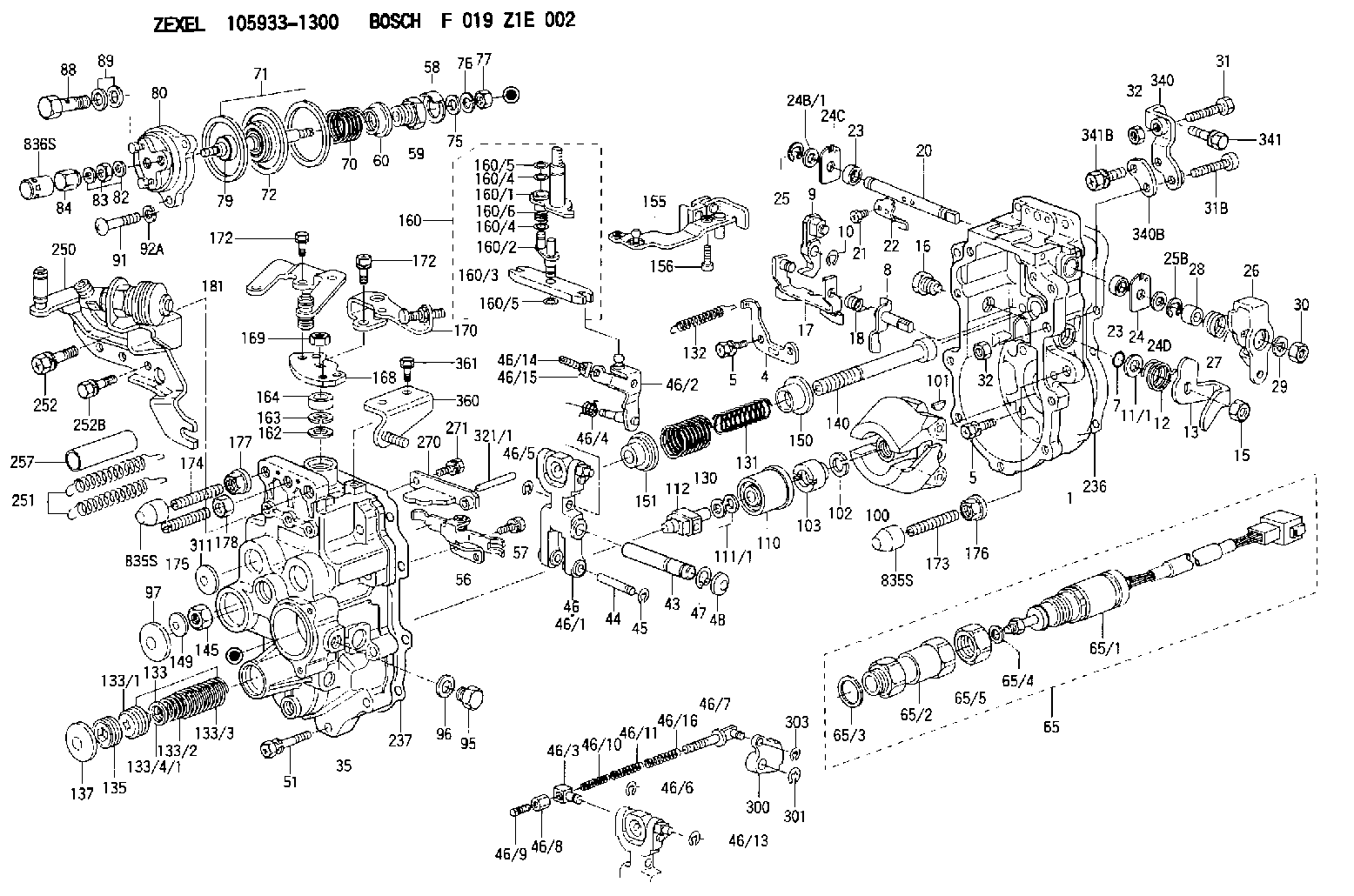
| 1. | [1] | 159360-0620 | GOVERNOR HOUSING |
| 4. | [1] | 159362-5120 | PLATE |
| 5. | [10] | 139006-6100 | BLEEDER SCREW |
| 5. | [10] | 139006-6100 | BLEEDER SCREW |
| 7. | [1] | 139709-0100 | O-RING |
| 8. | [1] | 159364-4820 | LEVER SHAFT |
| 9. | [1] | 159362-6620 | CONTROL LEVER |
| 10. | [1] | 016010-0740 | LOCKING WASHER |
| 11/1. | [0] | 029311-0220 | SHIM D18&10.3T0.2 |
| 11/1. | [0] | 029311-0230 | SHIM D18&10.3T0.5 |
| 11/1. | [0] | 029311-0430 | SHIM D18&10.3T0.30 |
| 11/1. | [0] | 029311-0440 | SHIM D18&10.3T0.40 |
| 11/1. | [0] | 029311-0450 | SHIM D18&10.3T0.25 |
| 11/1. | [0] | 029311-0460 | SHIM D18&10.3T0.35 |
| 11/1. | [0] | 139410-3300 | SHIM D18&10.3T0.6 |
| 11/1. | [0] | 139410-3400 | SHIM D18&10.3T0.8 |
| 11/1. | [0] | 139410-3500 | SHIM D18&10.3T0.9 |
| 12. | [1] | 159368-7900 | COILED SPRING |
| 13. | [1] | 159362-2500 | CONTROL LEVER |
| 15. | [1] | 013020-8040 | UNION NUT M8P1.25H7 |
| 16. | [1] | 159364-5000 | CAPSULE |
| 17. | [1] | 159362-2620 | CONTROL LEVER |
| 18. | [1] | 159215-0300 | COILED SPRING |
| 20. | [1] | 159364-9800 | LEVER SHAFT |
| 21. | [2] | 020104-1240 | BLEEDER SCREW |
| 22. | [1] | 159362-0600 | CONTROL LEVER |
| 23. | [2] | 139608-0600 | PACKING RING |
| 23. | [2] | 139608-0600 | PACKING RING |
| 24. | [1] | 159362-0700 | PLAIN WASHER |
| 24B/1. | [0] | 139408-1000 | SHIM D16&8T0.5 |
| 24B/1. | [0] | 139408-1300 | SHIM D16&8T0.2 |
| 24C. | [1] | 159362-0700 | PLAIN WASHER |
| 24D. | [1] | 139308-2100 | PLAIN WASHER |
| 25. | [1] | 159238-4200 | LOCKING WASHER |
| 25B. | [1] | 159238-4200 | LOCKING WASHER |
| 26. | [1] | 159390-9520 | CONTROL LEVER |
| 27. | [1] | 159369-2000 | COILED SPRING |
| 28. | [1] | 159364-6000 | BUSHING |
| 29. | [1] | 014110-8440 | LOCKING WASHER |
| 30. | [1] | 013020-8040 | UNION NUT M8P1.25H7 |
| 31. | [1] | 155644-1301 | BLEEDER SCREW |
| 31B. | [1] | 153505-0800 | FLAT-HEAD SCREW |
| 32. | [2] | 013030-6040 | UNION NUT M6P1H3.6 |
| 32. | [2] | 013030-6040 | UNION NUT M6P1H3.6 |
| 35. | [1] | 159361-1020 | GOVERNOR COVER |
| 43. | [1] | 159364-0700 | LEVER SHAFT |
| 44. | [1] | 159364-0800 | BEARING PIN |
| 45. | [2] | 016010-0640 | LOCKING WASHER |
| 46. | [1] | 159362-8620 | TENSIONING LEVER |
| 46/1. | [1] | 159362-8521 | TENSIONING LEVER |
| 46/2. | [1] | 159362-8721 | GUIDE LEVER |
| 46/3. | [1] | 159364-4201 | BEARING PIN |
| 46/4. | [1] | 159368-7700 | COILED SPRING |
| 46/5. | [1] | 016010-0540 | LOCKING WASHER |
| 46/6. | [1] | 016010-0440 | LOCKING WASHER |
| 46/7. | [1] | 159364-4121 | RACK |
| 46/8. | [1] | 159364-4300 | UNION NUT |
| 46/9. | [1] | 159364-4400 | FLAT-HEAD SCREW |
| 46/10. | [1] | 159368-6900 | COILED SPRING |
| 46/11. | [1] | 159368-7000 | COILED SPRING |
| 46/13. | [1] | 016010-0540 | LOCKING WASHER |
| 46/14. | [1] | 159364-1900 | FLAT-HEAD SCREW |
| 46/15. | [1] | 159364-1800 | UNION NUT |
| 46/16. | [1] | 159368-9500 | COILED SPRING |
| 47. | [2] | 016110-1020 | LOCKING WASHER |
| 48. | [2] | 159237-0200 | CAPSULE |
| 51. | [9] | 020106-3840 | BLEEDER SCREW |
| 56. | [1] | 159362-3720 | LEVER GROUP |
| 57. | [2] | 020105-1040 | BLEEDER SCREW M5P0.8L10 |
| 58. | [1] | 146711-0000 | PLATE |
| 59. | [1] | 154413-3600 | BUSHING |
| 60. | [1] | 146716-0000 | UNION NUT |
| 65. | [1] | 154612-8920 | RACK SENSOR ASSY |
| 65/1. | [1] | 479775-9420 | RACK SENSOR |
| 65/2. | [1] | 154614-8700 | JOINT CONNECTION |
| 65/3. | [1] | 026524-3040 | GASKET |
| 65/4. | [1] | 029310-6280 | SHIM D11.5&6.4T1.50 |
| 65/5. | [1] | 154614-1900 | UNION NUT |
| 70. | [1] | 154411-9700 | COILED SPRING |
| 71. | [2] | 154413-2600 | GASKET |
| 72. | [1] | 154415-1020 | DIAPHRAGM |
| 75. | [1] | 154415-1100 | SLOTTED WASHER |
| 76. | [1] | 014110-6440 | LOCKING WASHER |
| 77. | [1] | 013030-6010 | UNION NUT |
| 79. | [1] | 154413-4000 | FLAT-HEAD SCREW |
| 80. | [1] | 154404-5600 | COVER |
| 82. | [2] | 026506-1040 | GASKET D9.9&6.2T1 |
| 83. | [1] | 013030-6040 | UNION NUT M6P1H3.6 |
| 84. | [1] | 154035-1600 | CAP NUT |
| 88. | [1] | 029731-0180 | EYE BOLT |
| 89. | [2] | 026510-1340 | GASKET D13.4&10.2T1 |
| 91. | [3] | 154062-2900 | BLEEDER SCREW |
| 92A. | [3] | 014110-6440 | LOCKING WASHER |
| 95. | [1] | 029111-2090 | CAPSULE |
| 96. | [1] | 029331-2130 | GASKET |
| 97. | [1] | 159364-2000 | CAPSULE |
| 100. | [1] | 154101-1020 | FLYWEIGHT ASSEMBLY |
| 101. | [1] | 025803-1310 | WOODRUFF KEY |
| 102. | [1] | 029321-2020 | LOCKING WASHER |
| 103. | [1] | 029231-2030 | UNION NUT |
| 110. | [1] | 154123-2320 | SLIDING PIECE |
| 111/1. | [0] | 029311-0010 | SHIM D14&10.1T0.2 |
| 111/1. | [0] | 029311-0180 | SHIM D14&10.1T0.3 |
| 111/1. | [0] | 029311-0190 | SHIM D14&10.1T0.40 |
| 111/1. | [0] | 029311-0210 | SHIM D14&10.1T1 |
| 111/1. | [0] | 139410-0000 | SHIM D14.0&10.1T0.5 |
| 111/1. | [0] | 139410-0100 | SHIM D14.0&10.1T1.5 |
| 111/1. | [0] | 139410-3000 | SHIM D14&10.1T2.0 |
| 111/1. | [0] | 139410-3100 | SHIM D14&10.1T3.0 |
| 111/1. | [0] | 139410-3200 | SHIM D14&10.1T4.0 |
| 112. | [1] | 159364-2100 | TERMINAL STUD |
| 130. | [1] | 159367-4400 | GOVERNOR SPRING |
| 131. | [1] | 159367-6200 | GOVERNOR SPRING |
| 132. | [1] | 159368-6500 | COILED SPRING |
| 133. | [1] | 159368-3820 | SPRING PACK |
| 133/1. | [1] | 159364-2200 | GUIDE SLEEVE |
| 133/2. | [1] | 159368-1300 | COILED SPRING |
| 133/3. | [1] | 159368-0400 | COILED SPRING |
| 133/4/1. | [0] | 029311-0010 | SHIM D14&10.1T0.2 |
| 133/4/1. | [0] | 029311-0180 | SHIM D14&10.1T0.3 |
| 133/4/1. | [0] | 029311-0190 | SHIM D14&10.1T0.40 |
| 133/4/1. | [0] | 029311-0210 | SHIM D14&10.1T1 |
| 133/4/1. | [0] | 139410-0000 | SHIM D14.0&10.1T0.5 |
| 133/4/1. | [0] | 139410-0100 | SHIM D14.0&10.1T1.5 |
| 133/4/1. | [0] | 139410-3000 | SHIM D14&10.1T2.0 |
| 133/4/1. | [0] | 139410-3100 | SHIM D14&10.1T3.0 |
| 133/4/1. | [0] | 139410-3200 | SHIM D14&10.1T4.0 |
| 135. | [1] | 159364-2300 | FLAT-HEAD SCREW |
| 137. | [1] | 159364-2000 | CAPSULE |
| 140. | [1] | 159364-2500 | LEVER SHAFT |
| 145. | [1] | 159233-5700 | UNION NUT |
| 149. | [1] | 159237-5400 | CAPSULE |
| 150. | [1] | 159364-2600 | SLOTTED WASHER |
| 151. | [1] | 159364-2700 | SLOTTED WASHER |
| 155. | [1] | 159363-3220 | STRAP |
| 156. | [1] | 010235-1020 | HEX-SOCKET-HEAD CAP SCREW |
| 160. | [1] | 159362-7620 | LEVER GROUP |
| 160/1. | [1] | 159364-9420 | LEVER SHAFT |
| 160/2. | [1] | 159362-1020 | CONTROL LEVER |
| 160/3. | [1] | 159362-2000 | CONTROL LEVER |
| 160/4. | [2] | 159362-1300 | SHIM |
| 160/4. | [2] | 159362-1300 | SHIM |
| 160/5. | [2] | 016010-0840 | LOCKING WASHER |
| 160/5. | [2] | 016010-0840 | LOCKING WASHER |
| 160/6. | [1] | 159368-7400 | COILED SPRING |
| 162. | [1] | 139411-0600 | SHIM |
| 163. | [1] | 159238-3000 | LOCKING WASHER |
| 164. | [1] | 139610-0800 | PACKING RING |
| 168. | [1] | 159381-5800 | CONTROL LEVER |
| 169. | [1] | 013020-8040 | UNION NUT M8P1.25H7 |
| 170. | [1] | 159383-0120 | CONTROL LEVER |
| 172. | [4] | 020106-1240 | BLEEDER SCREW M6P1.0L12 |
| 172. | [4] | 020106-1240 | BLEEDER SCREW M6P1.0L12 |
| 173. | [1] | 154013-3800 | FLAT-HEAD SCREW |
| 173B. | [1] | 154013-3900 | FLAT-HEAD SCREW |
| 173C. | [1] | 154013-4600 | FLAT-HEAD SCREW |
| 174. | [1] | 154013-3700 | FLAT-HEAD SCREW |
| 174B. | [1] | 154013-4400 | FLAT-HEAD SCREW |
| 174C. | [1] | 154013-4700 | FLAT-HEAD SCREW |
| 175. | [1] | 154013-2100 | FLAT-HEAD SCREW |
| 176. | [1] | 154011-4800 | UNION NUT |
| 177. | [1] | 154011-4700 | UNION NUT |
| 178. | [1] | 139210-0300 | UNION NUT |
| 181. | [1] | 159383-0320 | CONTROL LEVER |
| 236. | [1] | 154390-4200 | GASKET |
| 237. | [1] | 154390-2500 | GASKET |
| 250. | [1] | 159400-0520 | CYLINDER |
| 251. | [2] | 154339-7100 | COILED SPRING |
| 252. | [1] | 010110-2040 | BLEEDER SCREW M10P1.25L20 |
| 252B. | [3] | 020106-1440 | BLEEDER SCREW M6P1.0L14 |
| 257. | [2] | 154156-2900 | TUBE |
| 270. | [1] | 159362-7320 | GUIDE PLATE |
| 271. | [2] | 020106-1640 | BLEEDER SCREW M6P1.0L14 |
| 300. | [1] | 159376-5200 | CAM PLATE |
| 301. | [1] | 016010-0840 | LOCKING WASHER |
| 303. | [1] | 016010-0540 | LOCKING WASHER |
| 311. | [2] | 159237-5400 | CAPSULE |
| 321/1. | [1] | 159274-5100 | STOP PIN L72.5 |
| 321/1. | [1] | 159274-5200 | STOP PIN L73 |
| 321/1. | [1] | 159274-5300 | STOP PIN L73.5 |
| 321/1. | [1] | 159274-5400 | STOP PIN L74 |
| 321/1. | [1] | 159274-5500 | STOP PIN L74.5 |
| 321/1. | [1] | 159274-5600 | STOP PIN L75 |
| 321/1. | [1] | 159274-5700 | STOP PIN L75.5 |
| 321/1. | [1] | 159274-5800 | STOP PIN L76 |
| 321/1. | [1] | 159274-5900 | STOP PIN L76.5 |
| 321/1. | [1] | 159274-6000 | STOP PIN L77 |
| 321/1. | [1] | 159274-6100 | STOP PIN L77.5 |
| 321/1. | [1] | 159274-6200 | STOP PIN L78 |
| 321/1. | [1] | 159274-6300 | STOP PIN L78.5 |
| 321/1. | [1] | 159274-6400 | STOP PIN L79 |
| 321/1. | [1] | 159274-6500 | STOP PIN L79.5 |
| 321/1. | [1] | 159274-6600 | STOP PIN L80 |
| 321/1. | [1] | 159274-6700 | STOP PIN L80.5 |
| 321/1. | [1] | 159274-6800 | STOP PIN L81 |
| 321/1. | [1] | 159274-6900 | STOP PIN L81.5 |
| 321/1. | [1] | 159274-7000 | STOP PIN L82 |
| 321/1. | [1] | 159274-7100 | STOP PIN L82.5 |
| 321/1. | [1] | 159274-7200 | STOP PIN L83 |
| 321/1. | [1] | 159274-7300 | STOP PIN L83.5 |
| 321/1. | [1] | 159274-7400 | STOP PIN L84 |
| 321/1. | [1] | 159274-7500 | STOP PIN L84.5 |
| 321/1. | [1] | 159274-7600 | STOP PIN L85 |
| 321/1. | [1] | 159274-7700 | STOP PIN L85.5 |
| 321/1. | [1] | 159274-7800 | STOP PIN L86 |
| 321/1. | [1] | 159274-7900 | STOP PIN L86.5 |
| 321/1. | [1] | 159274-8000 | STOP PIN L87 |
| 321/1. | [1] | 159274-8100 | STOP PIN L87.5 |
| 321/1. | [1] | 159274-8200 | STOP PIN L88 |
| 321/1. | [1] | 159274-8300 | STOP PIN L88.5 |
| 321/1. | [1] | 159274-8400 | STOP PIN L89 |
| 321/1. | [1] | 159274-8500 | STOP PIN L89.5 |
| 321/1. | [1] | 159274-8600 | STOP PIN L90 |
| 340. | [1] | 159397-0420 | BRACKET |
| 340B. | [1] | 159397-0500 | PLATE |
| 341. | [1] | 020106-1240 | BLEEDER SCREW M6P1.0L12 |
| 341B. | [1] | 020106-1840 | BLEEDER SCREW M6P1L18 |
| 360. | [1] | 159399-4320 | BRACKET |
| 361. | [2] | 020106-1240 | BLEEDER SCREW M6P1.0L12 |
| 835S. | [2] | 154062-3220 | CAP |
| 835S. | [2] | 154062-3220 | CAP |
| 836S. | [1] | 154062-2720 | CAP |
Include in #1:
107691-3411
as GOVERNOR
Cross reference number
Zexel num
Bosch num
Firm num
Name
105933-1300
224001630A HINO
GOVERNOR
A K 14JG MECHANICAL GOVERNOR GOV RLD-J(TICS) GOV
A K 14JG MECHANICAL GOVERNOR GOV RLD-J(TICS) GOV
105933-1300
S224001630A HINO
GOVERNOR
B K 14JG MECHANICAL GOVERNOR GOV RLD-J(TICS) GOV
B K 14JG MECHANICAL GOVERNOR GOV RLD-J(TICS) GOV
Information:
B. Back out (loosen) the lift adjustment screw 3/4 1/8of a turn.C. Put the nozzle in a vise with 8S2250 Holding Tool (1). Hold pressure adjusting screw (4) and tighten the locknut to a torque of 8.0-8.5 N m (70-75 lb in) using the 2P5487 Adapter (A). Recheck the opening pressure.Adjustment of 9L7883 Nozzles
1. Remove the nozzle from the tester and place in a vise using 8S2250 Nozzle Holding Tool (1). Loosen lift adjusting screw locknut (2). Loosen lift adjusting screw (3) two full turns counterclockwise.
If lift adjusting screw (3) is not loosened, the valve can be damaged in later steps.
2. Loosen pressure adjusting screw (4) and remove the nozzle from the nozzle holding tool. 3. Tilt the nozzle slightly down from the vertical position and remove pressure screw (4) and shims (5). If the shims do not come out of the nozzle, invert the nozzle and let the shims, spring and spring seat fall into the hand. If the valve comes out of its own weight, handle it carefully by its stem.4. To increase the opening pressure, add a 4N5730 Shim. The 4N5730 Shim is 0.13 mm (.005") thick and will increase the opening pressure approximately 1725 kPa (250 psi). A maximum of two shims can be added; if two shims do not increase opening pressure to specification given, discard the nozzle. 5. Assemble the nozzle, making sure the thickest shim (C) is against pressure screw (4). Put the nozzle in a vise using 8S2250 Nozzle Holding Tool (1). Tighten the pressure adjusting screw to 8.0-9.1 N m (70-80 lb in) torque.6. Remove the nozzle from the holding tool. Connect the nozzle, with the tip facing downward, to the tester. Point the nozzle tip into the 8S2270 Fuel Collector and the FT1384 Extension. Check the opening pressure and if it is not within specifications, repeat steps 4 and 5.Valve Lift Adjustment-9L7883 Nozzles
A. When the correct opening pressure is set, and while pumping test fluid through the nozzle, hold the lift adjusting screw locknut and slowly turn the lift adjusting screw clockwise (CW) until valve pressure rises 1380-3450 kPa (200-500 psi) above the nozzle opening pressure. Some test fluid may collect on the tip, but it must not flow at a rapid dribble.
Do not bend the valve by bottoming with too much force.
B. Back out the lift screw 3/4 1/8 turn, hold the lift adjusting screw, and tighten the locknut just enough so the screw will not turn; the lift is now set. C. Put the nozzle in a vise using 8S2250 Holding Tool (1). Tighten the locknut to 4.0-4.5 N m (35-40 lb in). Recheck valve opening pressure.Adjustment of 9L6969, 7N0449, 9N3299, 9N3700, 9N3979, 1W5829, 4W1819, 4W8483 and 7W3710 Nozzles
1. Put the nozzle in a vise using the 8S2250 Holding Tool (1). Loosen lift adjusting screw locknut (2). Turn lift adjusting screw (3) two full turns counterclockwise (CCW). 2. Hold lift adjusting screw (3) with a .08 mm (5/64") hex wrench (4) and