Information governor
BOSCH
9 420 614 892
9420614892
ZEXEL
105933-0743
1059330743
Rating:
Scheme ###:
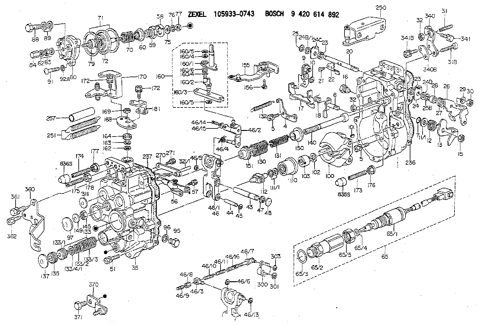
| 1. | [1] | 159360-0620 | GOVERNOR HOUSING |
| 4. | [1] | 159362-5120 | PLATE |
| 5. | [10] | 139006-6100 | BLEEDER SCREW |
| 5. | [10] | 139006-6100 | BLEEDER SCREW |
| 7. | [1] | 139709-0100 | O-RING |
| 8. | [1] | 159364-4820 | LEVER SHAFT |
| 9. | [1] | 159362-6620 | CONTROL LEVER |
| 10. | [1] | 016010-0740 | LOCKING WASHER |
| 11/1. | [0] | 029311-0220 | SHIM D18&10.3T0.2 |
| 11/1. | [0] | 029311-0230 | SHIM D18&10.3T0.5 |
| 11/1. | [0] | 029311-0430 | SHIM D18&10.3T0.30 |
| 11/1. | [0] | 029311-0440 | SHIM D18&10.3T0.40 |
| 11/1. | [0] | 029311-0450 | SHIM D18&10.3T0.25 |
| 11/1. | [0] | 029311-0460 | SHIM D18&10.3T0.35 |
| 11/1. | [0] | 139410-3300 | SHIM D18&10.3T0.6 |
| 11/1. | [0] | 139410-3400 | SHIM D18&10.3T0.8 |
| 11/1. | [0] | 139410-3500 | SHIM D18&10.3T0.9 |
| 12. | [1] | 159368-7900 | COILED SPRING |
| 13. | [1] | 159362-2500 | CONTROL LEVER |
| 15. | [1] | 013020-8040 | UNION NUT M8P1.25H7 |
| 16. | [1] | 159364-5000 | CAPSULE |
| 17. | [1] | 159362-2620 | CONTROL LEVER |
| 18. | [1] | 159215-0300 | COILED SPRING |
| 20. | [1] | 159364-9800 | LEVER SHAFT |
| 21. | [2] | 020104-1240 | BLEEDER SCREW |
| 22. | [1] | 159362-0600 | CONTROL LEVER |
| 23. | [2] | 139608-0600 | PACKING RING |
| 23. | [2] | 139608-0600 | PACKING RING |
| 24. | [1] | 159362-0700 | PLAIN WASHER |
| 24B/1. | [0] | 139408-1000 | SHIM D16&8T0.5 |
| 24B/1. | [0] | 139408-1300 | SHIM D16&8T0.2 |
| 24C. | [1] | 159362-0700 | PLAIN WASHER |
| 24D. | [1] | 139308-2100 | PLAIN WASHER |
| 25. | [1] | 159238-4200 | LOCKING WASHER |
| 25B. | [1] | 159238-4200 | LOCKING WASHER |
| 26. | [1] | 159390-6600 | CONTROL LEVER |
| 27. | [1] | 159369-2000 | COILED SPRING |
| 28. | [1] | 159364-6000 | BUSHING |
| 29. | [1] | 014110-8440 | LOCKING WASHER |
| 30. | [1] | 013020-8040 | UNION NUT M8P1.25H7 |
| 31. | [1] | 155615-1100 | FLAT-HEAD SCREW M6P1.0L37 |
| 31B. | [1] | 153505-0800 | FLAT-HEAD SCREW |
| 32. | [2] | 013030-6040 | UNION NUT M6P1H3.6 |
| 32. | [2] | 013030-6040 | UNION NUT M6P1H3.6 |
| 35. | [1] | 159361-1020 | GOVERNOR COVER |
| 43. | [1] | 159364-0700 | LEVER SHAFT |
| 44. | [1] | 159364-0800 | BEARING PIN |
| 45. | [2] | 016010-0640 | LOCKING WASHER |
| 46. | [1] | 159362-8620 | TENSIONING LEVER |
| 46/1. | [1] | 159362-8521 | TENSIONING LEVER |
| 46/2. | [1] | 159362-8721 | GUIDE LEVER |
| 46/3. | [1] | 159364-4201 | BEARING PIN |
| 46/4. | [1] | 159368-7700 | COILED SPRING |
| 46/5. | [1] | 016010-0540 | LOCKING WASHER |
| 46/6. | [1] | 016010-0440 | LOCKING WASHER |
| 46/7. | [1] | 159364-4121 | RACK |
| 46/8. | [1] | 159364-4300 | UNION NUT |
| 46/9. | [1] | 159364-4400 | FLAT-HEAD SCREW |
| 46/10. | [1] | 159368-6900 | COILED SPRING |
| 46/11. | [1] | 159368-7000 | COILED SPRING |
| 46/13. | [1] | 016010-0540 | LOCKING WASHER |
| 46/14. | [1] | 159364-1900 | FLAT-HEAD SCREW |
| 46/15. | [1] | 159364-1800 | UNION NUT |
| 46/16. | [1] | 159368-9500 | COILED SPRING |
| 47. | [2] | 016110-1020 | LOCKING WASHER |
| 48. | [2] | 159237-0200 | CAPSULE |
| 51. | [9] | 020106-3840 | BLEEDER SCREW |
| 56. | [1] | 159362-3720 | LEVER GROUP |
| 57. | [2] | 020105-1040 | BLEEDER SCREW M5P0.8L10 |
| 58. | [1] | 146711-0000 | PLATE |
| 59. | [1] | 154413-3600 | BUSHING |
| 60. | [1] | 146716-0000 | UNION NUT |
| 65. | [1] | 154612-5720 | RACK SENSOR ASSY |
| 65/1. | [1] | 479775-8620 | RACK SENSOR |
| 65/2. | [1] | 154614-8700 | JOINT CONNECTION |
| 65/3. | [1] | 026524-3040 | GASKET |
| 65/4. | [1] | 029310-6280 | SHIM D11.5&6.4T1.50 |
| 65/5. | [1] | 154614-1900 | UNION NUT |
| 70. | [1] | 154416-4500 | COILED SPRING |
| 71. | [2] | 154413-2600 | GASKET |
| 72. | [1] | 154415-1020 | DIAPHRAGM |
| 75. | [1] | 154415-1100 | SLOTTED WASHER |
| 76. | [1] | 014110-6440 | LOCKING WASHER |
| 77. | [1] | 013030-6010 | UNION NUT |
| 79. | [1] | 154413-4000 | FLAT-HEAD SCREW |
| 80. | [1] | 154404-5600 | COVER |
| 82. | [2] | 026506-1040 | GASKET D9.9&6.2T1 |
| 83. | [1] | 013030-6040 | UNION NUT M6P1H3.6 |
| 84. | [1] | 154035-1600 | CAP NUT |
| 88. | [1] | 029731-0180 | EYE BOLT |
| 89. | [2] | 026510-1340 | GASKET D13.4&10.2T1 |
| 91. | [3] | 154062-2900 | BLEEDER SCREW |
| 92A. | [3] | 014110-6440 | LOCKING WASHER |
| 95. | [1] | 029111-2090 | CAPSULE |
| 96. | [1] | 029331-2130 | GASKET |
| 97. | [1] | 159364-2000 | CAPSULE |
| 100. | [1] | 154101-1020 | FLYWEIGHT ASSEMBLY |
| 101. | [1] | 025803-1310 | WOODRUFF KEY |
| 102. | [1] | 029321-2020 | LOCKING WASHER |
| 103. | [1] | 029231-2030 | UNION NUT |
| 110. | [1] | 154123-2320 | SLIDING PIECE |
| 111/1. | [0] | 029311-0010 | SHIM D14&10.1T0.2 |
| 111/1. | [0] | 029311-0180 | SHIM D14&10.1T0.3 |
| 111/1. | [0] | 029311-0190 | SHIM D14&10.1T0.40 |
| 111/1. | [0] | 029311-0210 | SHIM D14&10.1T1 |
| 111/1. | [0] | 139410-0000 | SHIM D14.0&10.1T0.5 |
| 111/1. | [0] | 139410-0100 | SHIM D14.0&10.1T1.5 |
| 111/1. | [0] | 139410-3000 | SHIM D14&10.1T2.0 |
| 111/1. | [0] | 139410-3100 | SHIM D14&10.1T3.0 |
| 111/1. | [0] | 139410-3200 | SHIM D14&10.1T4.0 |
| 112. | [1] | 159364-2100 | TERMINAL STUD |
| 130. | [1] | 159367-1600 | GOVERNOR SPRING |
| 131. | [1] | 159367-6600 | GOVERNOR SPRING |
| 132. | [1] | 159368-6500 | COILED SPRING |
| 133. | [1] | 159368-3820 | SPRING PACK |
| 133/1. | [1] | 159364-2200 | GUIDE SLEEVE |
| 133/2. | [1] | 159368-1300 | COILED SPRING |
| 133/3. | [1] | 159368-0400 | COILED SPRING |
| 133/4/1. | [0] | 029311-0010 | SHIM D14&10.1T0.2 |
| 133/4/1. | [0] | 029311-0180 | SHIM D14&10.1T0.3 |
| 133/4/1. | [0] | 029311-0190 | SHIM D14&10.1T0.40 |
| 133/4/1. | [0] | 029311-0210 | SHIM D14&10.1T1 |
| 133/4/1. | [0] | 139410-0000 | SHIM D14.0&10.1T0.5 |
| 133/4/1. | [0] | 139410-0100 | SHIM D14.0&10.1T1.5 |
| 133/4/1. | [0] | 139410-3000 | SHIM D14&10.1T2.0 |
| 133/4/1. | [0] | 139410-3100 | SHIM D14&10.1T3.0 |
| 133/4/1. | [0] | 139410-3200 | SHIM D14&10.1T4.0 |
| 135. | [1] | 159364-2300 | FLAT-HEAD SCREW |
| 137. | [1] | 159364-2000 | CAPSULE |
| 140. | [1] | 159364-2500 | LEVER SHAFT |
| 145. | [1] | 159233-5700 | UNION NUT |
| 149. | [1] | 159237-5400 | CAPSULE |
| 150. | [1] | 159364-2600 | SLOTTED WASHER |
| 151. | [1] | 159364-2700 | SLOTTED WASHER |
| 155. | [1] | 159363-3220 | STRAP |
| 156. | [1] | 010235-1020 | HEX-SOCKET-HEAD CAP SCREW |
| 160. | [1] | 159362-3420 | LEVER GROUP |
| 160/1. | [1] | 159364-4920 | LEVER SHAFT |
| 160/2. | [1] | 159362-1020 | CONTROL LEVER |
| 160/3. | [1] | 159362-2000 | CONTROL LEVER |
| 160/4. | [2] | 159362-1300 | SHIM |
| 160/4. | [2] | 159362-1300 | SHIM |
| 160/5. | [2] | 016010-0840 | LOCKING WASHER |
| 160/5. | [2] | 016010-0840 | LOCKING WASHER |
| 160/6. | [1] | 159368-7400 | COILED SPRING |
| 162. | [1] | 139411-0600 | SHIM |
| 163. | [1] | 159238-3000 | LOCKING WASHER |
| 164. | [1] | 139610-0800 | PACKING RING |
| 168. | [1] | 159380-0300 | CONTROL LEVER |
| 169. | [1] | 013020-8040 | UNION NUT M8P1.25H7 |
| 170. | [1] | 159382-6420 | CONTROL LEVER |
| 172. | [4] | 020106-1240 | BLEEDER SCREW M6P1.0L12 |
| 172. | [4] | 020106-1240 | BLEEDER SCREW M6P1.0L12 |
| 173. | [1] | 154013-3800 | FLAT-HEAD SCREW |
| 173B. | [1] | 154013-3900 | FLAT-HEAD SCREW |
| 173C. | [1] | 154013-4600 | FLAT-HEAD SCREW |
| 174. | [1] | 154013-3700 | FLAT-HEAD SCREW |
| 174B. | [1] | 154013-4400 | FLAT-HEAD SCREW |
| 174C. | [1] | 154013-4700 | FLAT-HEAD SCREW |
| 175. | [1] | 154013-2100 | FLAT-HEAD SCREW |
| 176. | [1] | 154011-4800 | UNION NUT |
| 177. | [1] | 154011-4700 | UNION NUT |
| 178. | [1] | 013131-0040 | UNION NUT M10P1.25H6 |
| 181. | [1] | 159383-0600 | CONTROL LEVER |
| 236. | [1] | 154390-4200 | GASKET |
| 237. | [1] | 154390-2500 | GASKET |
| 250. | [1] | 159398-7320 | BRACKET |
| 251. | [2] | 154339-4800 | COILED SPRING |
| 257. | [2] | 154156-2900 | TUBE |
| 270. | [1] | 159362-3520 | GUIDE PLATE |
| 271. | [2] | 020106-1640 | BLEEDER SCREW M6P1.0L14 |
| 300. | [1] | 159374-9900 | CAM PLATE |
| 301. | [1] | 016010-0840 | LOCKING WASHER |
| 303. | [1] | 016010-0540 | LOCKING WASHER |
| 311. | [2] | 159237-5400 | CAPSULE |
| 321/1. | [1] | 159274-5100 | STOP PIN L72.5 |
| 321/1. | [1] | 159274-5200 | STOP PIN L73 |
| 321/1. | [1] | 159274-5300 | STOP PIN L73.5 |
| 321/1. | [1] | 159274-5400 | STOP PIN L74 |
| 321/1. | [1] | 159274-5500 | STOP PIN L74.5 |
| 321/1. | [1] | 159274-5600 | STOP PIN L75 |
| 321/1. | [1] | 159274-5700 | STOP PIN L75.5 |
| 321/1. | [1] | 159274-5800 | STOP PIN L76 |
| 321/1. | [1] | 159274-5900 | STOP PIN L76.5 |
| 321/1. | [1] | 159274-6000 | STOP PIN L77 |
| 321/1. | [1] | 159274-6100 | STOP PIN L77.5 |
| 321/1. | [1] | 159274-6200 | STOP PIN L78 |
| 321/1. | [1] | 159274-6300 | STOP PIN L78.5 |
| 321/1. | [1] | 159274-6400 | STOP PIN L79 |
| 321/1. | [1] | 159274-6500 | STOP PIN L79.5 |
| 321/1. | [1] | 159274-6600 | STOP PIN L80 |
| 321/1. | [1] | 159274-6700 | STOP PIN L80.5 |
| 321/1. | [1] | 159274-6800 | STOP PIN L81 |
| 321/1. | [1] | 159274-6900 | STOP PIN L81.5 |
| 321/1. | [1] | 159274-7000 | STOP PIN L82 |
| 321/1. | [1] | 159274-7100 | STOP PIN L82.5 |
| 321/1. | [1] | 159274-7200 | STOP PIN L83 |
| 321/1. | [1] | 159274-7300 | STOP PIN L83.5 |
| 321/1. | [1] | 159274-7400 | STOP PIN L84 |
| 321/1. | [1] | 159274-7500 | STOP PIN L84.5 |
| 321/1. | [1] | 159274-7600 | STOP PIN L85 |
| 321/1. | [1] | 159274-7700 | STOP PIN L85.5 |
| 321/1. | [1] | 159274-7800 | STOP PIN L86 |
| 321/1. | [1] | 159274-7900 | STOP PIN L86.5 |
| 321/1. | [1] | 159274-8000 | STOP PIN L87 |
| 321/1. | [1] | 159274-8100 | STOP PIN L87.5 |
| 321/1. | [1] | 159274-8200 | STOP PIN L88 |
| 321/1. | [1] | 159274-8300 | STOP PIN L88.5 |
| 321/1. | [1] | 159274-8400 | STOP PIN L89 |
| 321/1. | [1] | 159274-8500 | STOP PIN L89.5 |
| 321/1. | [1] | 159274-8600 | STOP PIN L90 |
| 340. | [1] | 159397-0420 | BRACKET |
| 340B. | [1] | 159397-0500 | PLATE |
| 341. | [1] | 020106-1240 | BLEEDER SCREW M6P1.0L12 |
| 341B. | [1] | 020106-1840 | BLEEDER SCREW M6P1L18 |
| 360. | [1] | 159398-8820 | BRACKET |
| 361. | [1] | 010110-2040 | BLEEDER SCREW M10P1.25L20 |
| 362. | [2] | 020106-1440 | BLEEDER SCREW M6P1.0L14 |
| 370. | [1] | 159399-1600 | BRACKET |
| 371. | [1] | 139012-0100 | BLEEDER SCREW |
| 835S. | [2] | 154062-3220 | CAP |
| 836S. | [1] | 154062-2720 | CAP |
Include in #1:
107691-3225
as GOVERNOR
Cross reference number
Zexel num
Bosch num
Firm num
Name
Information:
Installation of Oil Seal Case
(1) Coat the outside surface of the oil seal with engine oil.(2) Install the oil seal on the oil seal case.(3) Coat the lip of the oil seal with engine oil.(4) Install the O-ring into the oil seal case, and install the oil seal case on the flywheel housing. The oil seal case must be installed with the "Q" mark facing up.(5) Secure the oil seal case with the bolts.
Installation of oil seal caseInstallation of Flywheel
(1) Install the flywheel to the crankshaft by aligning the hole with the dowel pin on the back-end of the crankshaft.(2) Place the washer and tighten the four bolts to the specified torque.
Installation of flywheelMeasurement of Flywheel Axial and Radial Runouts
Measure the flywheel runout with the flywheel installed to the crankshaft. If the standard value is exceeded, check the bolts for tightening condition and the mounting face for adhesion of foreign particles.
Measurement of face runout and circular runoutCylinder Head and Valve Mechanisms
Installation of Valve Stem Seals
(1) Apply engine oil to the valve stem, and insert it into the valve guide.(2) Place a new stem seal on the valve guide.(3) Using the stem seal installer, install the stem seal to the valve guide, making use of the valve stem as a guide.
Installation of valve stem sealInstallation of Valves and Valve Springs
(1) Place the valve spring and retainer on the valve guide, and install the valve cotter using the valve spring pusher.
Excessive compression of the valve spring can cause the retainer to contact the stem seal and damage the seal.
Installation of valve and valve spring(2) Using a soft-faced hammer, tap the top of the valve stem several times to make sure that the spring and valve cotter are securely installed.
Confirmation of secure valve cotter installationInstallation of Cylinder Head Gasket
(1) Make sure that the top face of the crankcase and piston upper surfaces are clean and free of dust.(2) Place a new gasket of the crankcase, making sure that the dowel pins on the top face of the crankcase enter the holes in the gasket.
Do not use a liquid gasket.
Installation of cylinder head gasketInstallation of Cylinder Head
Place the cylinder head on the head gasket, making sure that the dowel pins on the top face of the crankcase enters the holes in the cylinder head.
Installation of cylinder headTightening of Cylinder Head Bolts
Tighten the cylinder head bolts, following the tightening sequence shown in the diagram two or three times before reaching the specified torque.
Cylinder head bolt tightening sequenceAssembly of Rocker Arm and Rocker Shaft Assembly
When installing the rocker arms, make sure that the shaft assembly marks face the front of the engine, as shown in the diagram. After the assembly, make sure that the rocker arms move smoothly.
Assembly of rocker shaft assemblyInstallation of Pushrods
(1) Insert the pushrods in the cylinder head through the pushrod holes.(2) Make sure that the ball end of each pushrod rests securely on the curved surface of the tappet.Installation of Rocker Shaft Assembly
(1) Install the valve caps.(2) Tighten the rocker