Information governor
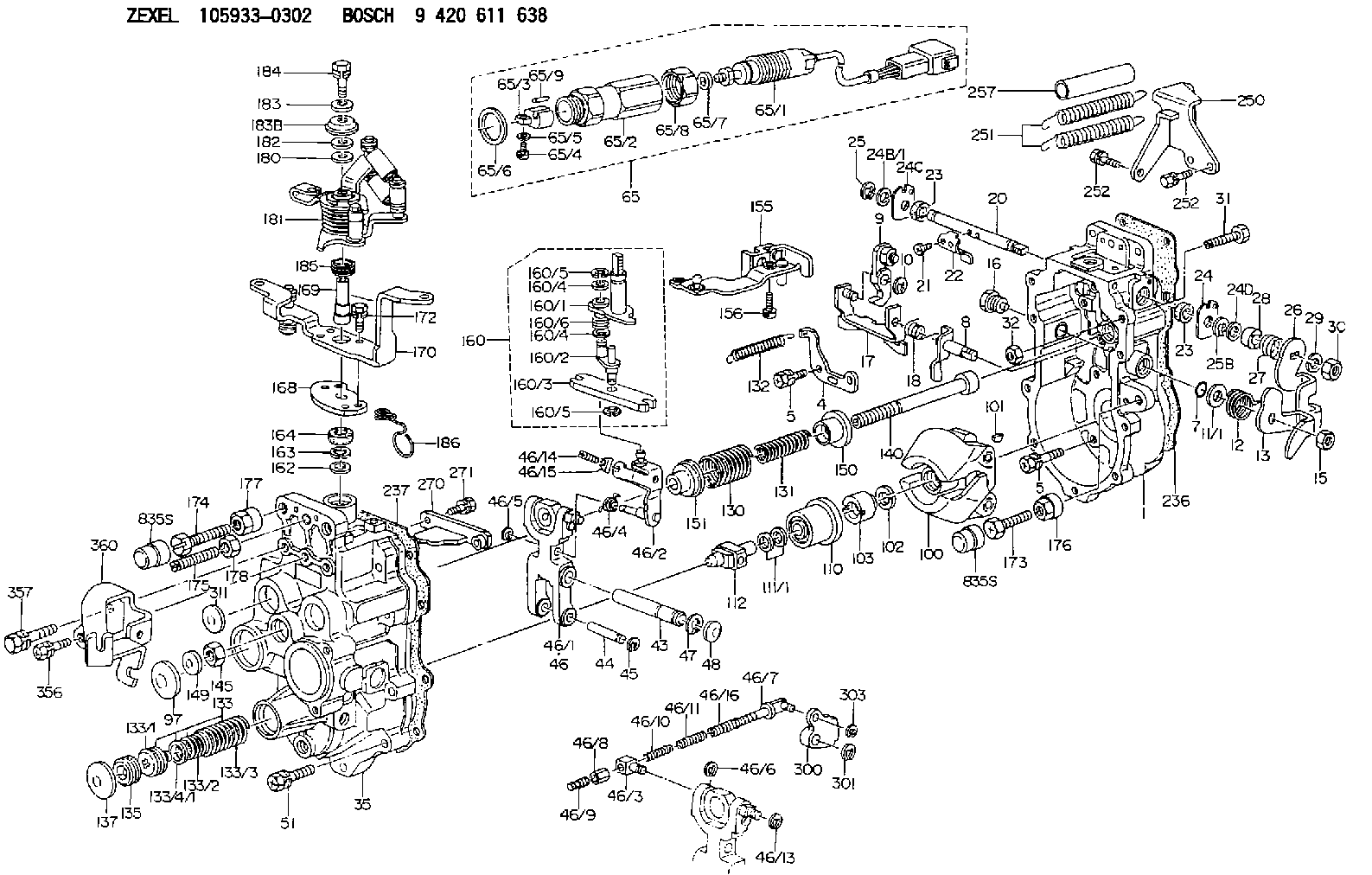
BOSCH
9 420 611 638
9420611638
ZEXEL
105933-0302
1059330302
MITSUBISHI
ME740866
me740866
Rating:
Scheme ###:
| 1. | [1] | 159360-0620 | GOVERNOR HOUSING |
| 4. | [1] | 159362-5120 | PLATE |
| 5. | [10] | 139006-6100 | BLEEDER SCREW |
| 5. | [10] | 139006-6100 | BLEEDER SCREW |
| 7. | [1] | 139709-0100 | O-RING |
| 8. | [1] | 159364-4820 | LEVER SHAFT |
| 9. | [1] | 159362-6520 | CONTROL LEVER |
| 10. | [1] | 016010-0740 | LOCKING WASHER |
| 11/1. | [0] | 029311-0220 | SHIM D18&10.3T0.2 |
| 11/1. | [0] | 029311-0230 | SHIM D18&10.3T0.5 |
| 11/1. | [0] | 029311-0430 | SHIM D18&10.3T0.30 |
| 11/1. | [0] | 029311-0440 | SHIM D18&10.3T0.40 |
| 11/1. | [0] | 029311-0450 | SHIM D18&10.3T0.25 |
| 11/1. | [0] | 029311-0460 | SHIM D18&10.3T0.35 |
| 11/1. | [0] | 139410-3300 | SHIM D18&10.3T0.6 |
| 11/1. | [0] | 139410-3400 | SHIM D18&10.3T0.8 |
| 11/1. | [0] | 139410-3500 | SHIM D18&10.3T0.9 |
| 12. | [1] | 159368-7900 | COILED SPRING |
| 13. | [1] | 159362-5300 | CONTROL LEVER |
| 15. | [1] | 013020-8040 | UNION NUT M8P1.25H7 |
| 16. | [1] | 159364-5000 | CAPSULE |
| 17. | [1] | 159362-5420 | CONTROL LEVER |
| 18. | [1] | 159215-0300 | COILED SPRING |
| 20. | [1] | 159364-9800 | LEVER SHAFT |
| 21. | [2] | 020104-1240 | BLEEDER SCREW |
| 22. | [1] | 159362-0600 | CONTROL LEVER |
| 23. | [2] | 139608-0600 | PACKING RING |
| 23. | [2] | 139608-0600 | PACKING RING |
| 24. | [1] | 159362-0700 | PLAIN WASHER |
| 24B/1. | [0] | 139408-1000 | SHIM D16&8T0.5 |
| 24B/1. | [0] | 139408-1300 | SHIM D16&8T0.2 |
| 24C. | [1] | 159362-0700 | PLAIN WASHER |
| 24D. | [1] | 139308-2100 | PLAIN WASHER |
| 25. | [1] | 159238-4200 | LOCKING WASHER |
| 25B. | [1] | 159238-4200 | LOCKING WASHER |
| 26. | [1] | 159390-3200 | CONTROL LEVER |
| 27. | [1] | 159368-6100 | COILED SPRING |
| 28. | [1] | 159364-6000 | BUSHING |
| 29. | [1] | 014110-8440 | LOCKING WASHER |
| 30. | [1] | 013020-8040 | UNION NUT M8P1.25H7 |
| 31. | [1] | 155644-1301 | BLEEDER SCREW |
| 32. | [1] | 013030-6040 | UNION NUT M6P1H3.6 |
| 35. | [1] | 159361-1120 | GOVERNOR COVER |
| 43. | [1] | 159364-0700 | LEVER SHAFT |
| 44. | [1] | 159364-0800 | BEARING PIN |
| 45. | [2] | 016010-0640 | LOCKING WASHER |
| 46. | [1] | 159362-8620 | TENSIONING LEVER |
| 46/1. | [1] | 159362-8521 | TENSIONING LEVER |
| 46/2. | [1] | 159362-8721 | GUIDE LEVER |
| 46/3. | [1] | 159364-4201 | BEARING PIN |
| 46/4. | [1] | 159368-7700 | COILED SPRING |
| 46/5. | [1] | 016010-0540 | LOCKING WASHER |
| 46/6. | [1] | 016010-0440 | LOCKING WASHER |
| 46/7. | [1] | 159364-4121 | RACK |
| 46/8. | [1] | 159364-4300 | UNION NUT |
| 46/9. | [1] | 159364-4400 | FLAT-HEAD SCREW |
| 46/10. | [1] | 159368-6900 | COILED SPRING |
| 46/11. | [1] | 159368-7000 | COILED SPRING |
| 46/13. | [1] | 016010-0540 | LOCKING WASHER |
| 46/14. | [1] | 159364-1900 | FLAT-HEAD SCREW |
| 46/15. | [1] | 159364-1800 | UNION NUT |
| 46/16. | [1] | 159368-9500 | COILED SPRING |
| 47. | [2] | 016110-1020 | LOCKING WASHER |
| 48. | [2] | 159237-0200 | CAPSULE |
| 51. | [9] | 020106-3840 | BLEEDER SCREW |
| 65. | [1] | 154611-4620 | RACK SENSOR ASSY |
| 65/1. | [1] | 479775-2120 | RACK SENSOR |
| 65/2. | [1] | 154614-2500 | JOINT CONNECTION |
| 65/3. | [1] | 154614-5300 | BLOCK |
| 65/4. | [1] | 010234-1040 | HEX-SOCKET-HEAD CAP SCREW |
| 65/5. | [1] | 014110-4440 | LOCKING WASHER |
| 65/6. | [1] | 026524-3040 | GASKET |
| 65/7A. | [0] | 029310-6220 | SHIM D11.5&6.5T0.10 |
| 65/7B. | [0] | 029310-6230 | SHIM D11.5&6.5T0.20 |
| 65/7C. | [0] | 029310-6240 | SHIM D11.5&6.5T0.25 |
| 65/7D. | [0] | 029310-6260 | SHIM D11.5&6.4T1.00 |
| 65/7E. | [0] | 029310-6270 | SHIM D11.5&6.4T1.20 |
| 65/7F. | [0] | 029310-6280 | SHIM D11.5&6.4T1.50 |
| 65/8. | [1] | 154614-1900 | UNION NUT |
| 65/9. | [1] | 154614-3300 | BEARING PIN |
| 97. | [1] | 159364-2000 | CAPSULE |
| 100. | [1] | 154101-0920 | FLYWEIGHT ASSEMBLY |
| 101. | [1] | 025803-1310 | WOODRUFF KEY |
| 102. | [1] | 029321-2020 | LOCKING WASHER |
| 103. | [1] | 029231-2030 | UNION NUT |
| 110. | [1] | 154123-2320 | SLIDING PIECE |
| 111/1. | [0] | 029311-0010 | SHIM D14&10.1T0.2 |
| 111/1. | [0] | 029311-0180 | SHIM D14&10.1T0.3 |
| 111/1. | [0] | 029311-0190 | SHIM D14&10.1T0.40 |
| 111/1. | [0] | 029311-0210 | SHIM D14&10.1T1 |
| 111/1. | [0] | 139410-0000 | SHIM D14.0&10.1T0.5 |
| 111/1. | [0] | 139410-0100 | SHIM D14.0&10.1T1.5 |
| 111/1. | [0] | 139410-3000 | SHIM D14&10.1T2.0 |
| 111/1. | [0] | 139410-3100 | SHIM D14&10.1T3.0 |
| 111/1. | [0] | 139410-3200 | SHIM D14&10.1T4.0 |
| 112. | [1] | 159364-2100 | TERMINAL STUD |
| 130. | [1] | 159367-1400 | GOVERNOR SPRING |
| 131. | [1] | 159367-6400 | GOVERNOR SPRING |
| 132. | [1] | 159368-6500 | COILED SPRING |
| 133. | [1] | 159368-3620 | SPRING PACK |
| 133/1. | [1] | 159364-2200 | GUIDE SLEEVE |
| 133/2. | [1] | 159368-0200 | COILED SPRING |
| 133/3. | [1] | 159368-0300 | COILED SPRING |
| 133/4/1. | [0] | 029311-0010 | SHIM D14&10.1T0.2 |
| 133/4/1. | [0] | 029311-0180 | SHIM D14&10.1T0.3 |
| 133/4/1. | [0] | 029311-0190 | SHIM D14&10.1T0.40 |
| 133/4/1. | [0] | 029311-0210 | SHIM D14&10.1T1 |
| 133/4/1. | [0] | 139410-0000 | SHIM D14.0&10.1T0.5 |
| 133/4/1. | [0] | 139410-0100 | SHIM D14.0&10.1T1.5 |
| 133/4/1. | [0] | 139410-3000 | SHIM D14&10.1T2.0 |
| 133/4/1. | [0] | 139410-3100 | SHIM D14&10.1T3.0 |
| 133/4/1. | [0] | 139410-3200 | SHIM D14&10.1T4.0 |
| 135. | [1] | 159364-2300 | FLAT-HEAD SCREW |
| 137. | [1] | 159364-2000 | CAPSULE |
| 140. | [1] | 159364-2500 | LEVER SHAFT |
| 145. | [1] | 159233-5700 | UNION NUT |
| 149. | [1] | 159237-5400 | CAPSULE |
| 150. | [1] | 159364-2600 | SLOTTED WASHER |
| 151. | [1] | 159364-2700 | SLOTTED WASHER |
| 155. | [1] | 159363-3620 | STRAP |
| 156. | [1] | 010235-1020 | HEX-SOCKET-HEAD CAP SCREW |
| 160. | [1] | 159362-7620 | LEVER GROUP |
| 160/1. | [1] | 159364-9420 | LEVER SHAFT |
| 160/2. | [1] | 159362-1020 | CONTROL LEVER |
| 160/3. | [1] | 159362-2000 | CONTROL LEVER |
| 160/4. | [2] | 159362-1300 | SHIM |
| 160/4. | [2] | 159362-1300 | SHIM |
| 160/5. | [2] | 016010-0840 | LOCKING WASHER |
| 160/5. | [2] | 016010-0840 | LOCKING WASHER |
| 160/6. | [1] | 159368-7400 | COILED SPRING |
| 162. | [1] | 139411-0600 | SHIM |
| 163. | [1] | 159238-3000 | LOCKING WASHER |
| 164. | [1] | 139610-0800 | PACKING RING |
| 168. | [1] | 159381-5800 | CONTROL LEVER |
| 169. | [1] | 159233-7700 | UNION NUT |
| 170. | [1] | 159381-3420 | CONTROL LEVER |
| 172. | [3] | 020106-1240 | BLEEDER SCREW M6P1.0L12 |
| 173. | [1] | 154013-1700 | BLEEDER SCREW |
| 173B. | [1] | 154013-1800 | BLEEDER SCREW |
| 173C. | [1] | 154013-1900 | BLEEDER SCREW |
| 174. | [1] | 154013-2000 | BLEEDER SCREW |
| 175. | [1] | 154013-2100 | FLAT-HEAD SCREW |
| 176. | [1] | 154011-4000 | UNION NUT |
| 177. | [1] | 154011-4100 | UNION NUT |
| 178. | [1] | 013131-0040 | UNION NUT M10P1.25H6 |
| 180. | [1] | 139310-0500 | PLAIN WASHER |
| 181. | [1] | 159381-3820 | CONTROL LEVER |
| 181. | [1] | 159381-3820 | CONTROL LEVER |
| 182. | [0] | 029311-0010 | SHIM D14&10.1T0.2 |
| 183. | [1] | 014010-6140 | PLAIN WASHER D13&6.5T1 |
| 183B. | [1] | 159235-7500 | CAP |
| 184. | [1] | 020006-1270 | BLEEDER SCREW M6P1L12 7T |
| 185. | [1] | 159369-0400 | COILED SPRING |
| 186. | [1] | 159220-1300 | CLAMPING BAND |
| 236. | [1] | 154390-4200 | GASKET |
| 237. | [1] | 154390-2500 | GASKET |
| 250. | [1] | 159397-3820 | BRACKET |
| 251. | [2] | 154338-8600 | COILED SPRING |
| 252. | [3] | 020106-1240 | BLEEDER SCREW M6P1.0L12 |
| 252. | [3] | 020106-1240 | BLEEDER SCREW M6P1.0L12 |
| 257. | [2] | 154156-0900 | TUBE |
| 270. | [1] | 159362-6920 | GUIDE PLATE |
| 271. | [2] | 020106-1640 | BLEEDER SCREW M6P1.0L14 |
| 300. | [1] | 159373-5400 | CAM PLATE |
| 301. | [1] | 016010-0840 | LOCKING WASHER |
| 303. | [1] | 016010-0540 | LOCKING WASHER |
| 311. | [2] | 159237-5400 | CAPSULE |
| 356. | [2] | 020106-1440 | BLEEDER SCREW M6P1.0L14 |
| 357. | [1] | 010110-1640 | BLEEDER SCREW M101.25L16 |
| 360. | [1] | 159396-2921 | BRACKET |
| 835S. | [2] | 154062-1700 | CAP D20L32 |
| 835S. | [2] | 154062-1700 | CAP D20L32 |
Include in #1:
107691-2252
as GOVERNOR
Cross reference number
Zexel num
Bosch num
Firm num
Name
Information:
Cylinder Liner
Use same piston which was removed from cylinder liner being checked.Use the following procedure to check a liner:
Fig. 6-Piston to Liner Clearance1. Put piston in liner with piston "front" and liner "front" aligned. Move piston down until bottom edge of piston skirt is 1.00 in. (25.4 mm) (1, Fig. 6) above bottom of liner.Use a feeler gauge to measure distance (2) between piston skirt and liner 90° to piston pin bore. Record the measured distance (2).Piston to cylinder liner clearance for new parts is: 2. Turn piston 90° in liner. Use a feeler gauge to measure distance between piston skirt and liner 90° to piston pin bore. Record the measured distance.The difference between the distance measured in Step 1 and the distance in Step 2 is the distance the liner is out of round at the bottom of the liner.
Fig. 7-Piston to Liner Clearance3. Pull piston out of liner. Put piston in liner up-side down with piston "front" and liner "front" aligned. Move piston so bottom edge of piston skirt is 1.00 in. (25.4 mm) (1, Fig. 7) below top of liner.Use a feeler gauge to measure distance (2) between piston skirt and liner at 90° to piston pin bore. Record the measured distance (2).4. Turn piston 90° in liner. Use a feeler gauge to measure distance between piston skirt and liner 90° to piston pin bore. Record the measured distance.The difference between the distance measured in Step 3 and the distance measured in Step 4 is the distance the liner is out of round at the top of the liner.If liner is out of round more than 0.002 in. (0.05 mm), at top or bottom, install a new one.5. Find difference between distance measured in Step 1 and distance measured in Step 3. This is the distance the liner is tapered.If liner is tapered more than 0.002 in. (0.05 mm), install a new one.Use a wire brush to carefully remove all rust and scale from the outside of the cylinder liners. Make certain there are no nicks or burrs in the areas where the packings will seat.After removing the rust and scale from the cylinder liners wash thoroughly with solvent and dry them.
Fig. 8-D17004BR Cylinder BrushUse D17004BR Cylinder Brush (Fig. 8) to deglaze each cylinder liner. Match the existing cross hatch pattern when deglazing.Refer to "Basic Engine" in FOS Manual-ENGINES for additional information on deglazing cylinder liners.Immediately after deglazing, clean cylinder liner bore with waterless hand cleaner or soap. Rinse cylinder liner bores with clean water until rinse water is clear. Dry liners with clean towels. Wipe bore with clean engine oil. IMPORTANT: Solvents will not remove honing residue.Recheck liner-to-piston skirt clearance. See Group 0403 for piston repair.Piston Cooling Orifices
Inspect for damage or clogging.
Fig. 9-Piston Cooling OrificeIf a piston cooling orifice (2, Fig. 9) is clogged, use a soft wire (1) to push material out of hole.If an orifice is damaged install a new one.Installation
Fig. 10-Piston Cooling OrificesInstall piston cooling orifices (Fig. 10) and tighten to