Information governor
BOSCH
F 019 Z1E 937
f019z1e937
ZEXEL
105932-3630
1059323630
MITSUBISHI
ME755446
me755446
Rating:
Scheme ###:
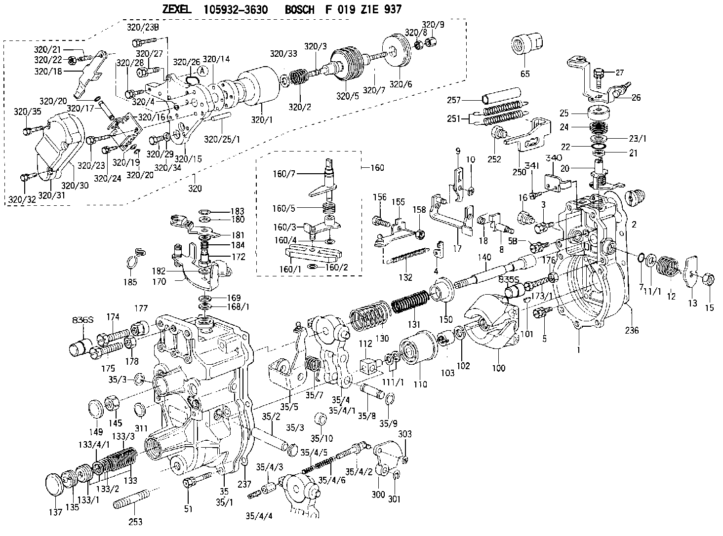
| 1. | [1] | 159200-4220 | GOVERNOR HOUSING |
| 2. | [1] | 154007-0200 | ADAPTOR |
| 3. | [1] | 020018-1840 | BLEEDER SCREW M8P1.25L18 |
| 4. | [1] | 159232-2620 | PLATE |
| 5. | [5] | 029010-6810 | BLEEDER SCREW |
| 5B. | [1] | 020106-1640 | BLEEDER SCREW M6P1.0L14 |
| 7. | [1] | 016530-1010 | O-RING |
| 8. | [1] | 159205-2321 | LEVER SHAFT |
| 9. | [1] | 159202-5101 | CONTROL LEVER |
| 10. | [1] | 016010-0810 | LOCKING WASHER |
| 11/1. | [0] | 029311-0220 | SHIM D18&10.3T0.2 |
| 11/1. | [0] | 029311-0230 | SHIM D18&10.3T0.5 |
| 11/1. | [0] | 029311-0430 | SHIM D18&10.3T0.30 |
| 11/1. | [0] | 029311-0440 | SHIM D18&10.3T0.40 |
| 11/1. | [0] | 029311-0450 | SHIM D18&10.3T0.25 |
| 11/1. | [0] | 029311-0460 | SHIM D18&10.3T0.35 |
| 11/1. | [0] | 139410-3300 | SHIM D18&10.3T0.6 |
| 11/1. | [0] | 139410-3400 | SHIM D18&10.3T0.8 |
| 11/1. | [0] | 139410-3500 | SHIM D18&10.3T0.9 |
| 12. | [1] | 159215-0000 | COILED SPRING |
| 13. | [1] | 159242-6601 | CONTROL LEVER |
| 15. | [1] | 013020-8040 | UNION NUT M8P1.25H7 |
| 16. | [1] | 159237-5500 | CAPSULE |
| 17. | [1] | 159202-5220 | CONTROL LEVER |
| 18. | [1] | 159215-0300 | COILED SPRING |
| 20. | [1] | 159242-0220 | CONTROL LEVER |
| 21. | [1] | 159242-0600 | BUSHING |
| 22. | [1] | 016530-1010 | O-RING |
| 23/1. | [0] | 029311-0220 | SHIM D18&10.3T0.2 |
| 23/1. | [0] | 029311-0230 | SHIM D18&10.3T0.5 |
| 23/1. | [0] | 029311-0430 | SHIM D18&10.3T0.30 |
| 23/1. | [0] | 029311-0440 | SHIM D18&10.3T0.40 |
| 23/1. | [0] | 029311-0450 | SHIM D18&10.3T0.25 |
| 23/1. | [0] | 029311-0460 | SHIM D18&10.3T0.35 |
| 23/1. | [0] | 139410-3300 | SHIM D18&10.3T0.6 |
| 23/1. | [0] | 139410-3400 | SHIM D18&10.3T0.8 |
| 23/1. | [0] | 139410-3500 | SHIM D18&10.3T0.9 |
| 24. | [1] | 159215-2000 | COILED SPRING |
| 25. | [1] | 159235-5800 | CAP |
| 26. | [1] | 159249-6920 | CONTROL LEVER |
| 27. | [1] | 020006-1640 | BLEEDER SCREW M6P1L16 4T |
| 35. | [1] | 159255-5720 | GOVERNOR COVER |
| 35/1. | [1] | 159201-3522 | GOVERNOR COVER |
| 35/2. | [1] | 159205-0400 | LEVER SHAFT |
| 35/3. | [2] | 159237-0200 | CAPSULE |
| 35/3. | [2] | 159237-0200 | CAPSULE |
| 35/4. | [1] | 159253-2220 | TENSIONING LEVER |
| 35/4/1. | [1] | 159203-1720 | TENSIONING LEVER |
| 35/4/2. | [1] | 159204-5021 | RACK |
| 35/4/3. | [1] | 159233-0300 | UNION NUT |
| 35/4/4. | [1] | 159234-0300 | FLAT-HEAD SCREW |
| 35/4/5. | [1] | 159216-0000 | COILED SPRING |
| 35/4/6. | [1] | 159216-0100 | COILED SPRING |
| 35/5. | [1] | 159203-6120 | GUIDE LEVER |
| 35/7. | [1] | 159215-1701 | COILED SPRING |
| 35/8. | [1] | 159231-1300 | BEARING PIN |
| 35/9. | [2] | 016010-0610 | LOCKING WASHER |
| 35/10. | [1] | 159238-2900 | BUSHING |
| 51. | [7] | 020106-3840 | BLEEDER SCREW |
| 65. | [1] | 154050-1720 | STOPPING DEVICE |
| 100. | [1] | 154100-9520 | FLYWEIGHT ASSEMBLY |
| 101. | [1] | 025803-1610 | WOODRUFF KEY |
| 102. | [1] | 029321-2020 | LOCKING WASHER |
| 103. | [1] | 029231-2030 | UNION NUT |
| 110. | [1] | 154123-2320 | SLIDING PIECE |
| 111/1. | [0] | 029311-0010 | SHIM D14&10.1T0.2 |
| 111/1. | [0] | 029311-0180 | SHIM D14&10.1T0.3 |
| 111/1. | [0] | 029311-0190 | SHIM D14&10.1T0.40 |
| 111/1. | [0] | 029311-0210 | SHIM D14&10.1T1 |
| 111/1. | [0] | 139410-0000 | SHIM D14.0&10.1T0.5 |
| 111/1. | [0] | 139410-0100 | SHIM D14.0&10.1T1.5 |
| 111/1. | [0] | 139410-3000 | SHIM D14&10.1T2.0 |
| 111/1. | [0] | 139410-3100 | SHIM D14&10.1T3.0 |
| 111/1. | [0] | 139410-3200 | SHIM D14&10.1T4.0 |
| 112. | [1] | 159236-0200 | TERMINAL STUD |
| 130. | [1] | 159210-3200 | GOVERNOR SPRING |
| 131. | [1] | 159211-3000 | GOVERNOR SPRING |
| 132. | [1] | 159214-0000 | COILED SPRING |
| 133. | [1] | 159212-5320 | SPRING PACK |
| 133/1. | [1] | 159234-5602 | GUIDE SLEEVE |
| 133/2. | [1] | 159212-5000 | COILED SPRING |
| 133/3. | [1] | 159212-5300 | COILED SPRING |
| 133/4/1. | [0] | 029310-9240 | SHIM D11.9&9T0.1 |
| 133/4/1. | [0] | 029310-9250 | SHIM D11.9&9T0.2 |
| 133/4/1. | [0] | 029310-9260 | SHIM D11.9&9T0.25 |
| 133/4/1. | [0] | 029310-9270 | SHIM D11.9&9T1.0 |
| 133/4/1. | [0] | 139409-0100 | SHIM D11.9&9T0.3 |
| 133/4/1. | [0] | 139409-0200 | SHIM D11.9&9T0.5 |
| 133/4/1. | [0] | 139409-0300 | SHIM D11.5&9T0.8 |
| 135. | [1] | 159248-2700 | FLAT-HEAD SCREW |
| 137. | [1] | 159237-5300 | CAPSULE |
| 140. | [1] | 159205-2101 | LEVER SHAFT |
| 145. | [1] | 159233-5700 | UNION NUT |
| 149. | [1] | 159237-5400 | CAPSULE |
| 150. | [1] | 159235-5300 | SLOTTED WASHER |
| 155. | [1] | 159204-7720 | STRAP |
| 156. | [1] | 159233-0520 | BLEEDER SCREW |
| 158. | [1] | 013020-5240 | UNION NUT M5P0.8H4 |
| 160. | [1] | 159252-0821 | LEVER GROUP |
| 160/1. | [1] | 159202-2200 | CONTROL LEVER |
| 160/2. | [1] | 016010-0810 | LOCKING WASHER |
| 160/3. | [1] | 159202-2120 | CONTROL LEVER |
| 160/4. | [1] | 016010-0810 | LOCKING WASHER |
| 160/5. | [1] | 159215-2301 | COILED SPRING |
| 160/7. | [1] | 159205-2222 | LEVER SHAFT |
| 168/1. | [0] | 029311-0640 | SHIM D26.0&10.2T0.95 |
| 168/1. | [0] | 029311-0650 | SHIM D26.0&10.2T0.20 |
| 168/1. | [0] | 029311-0660 | SHIM D26.0&10.2T0.25 |
| 168/1. | [0] | 029311-0670 | SHIM D26.0&10.2T0.30 |
| 168/1. | [0] | 029311-0680 | SHIM D26.0&10.2T0.35 |
| 168/1. | [0] | 029311-0690 | SHIM D26.0&10.2T0.40 |
| 168/1. | [0] | 029311-0700 | SHIM D26.0&10.2T0.50 |
| 168/1. | [0] | 139410-1400 | SHIM D26&10.2T0.7 |
| 168/1. | [0] | 139410-1500 | SHIM D26&10.2T0.9 |
| 168/1. | [0] | 139410-1600 | SHIM D26&10.2T0.8 |
| 168/1. | [0] | 139410-2700 | SHIM D26&10.2T0.6 |
| 169. | [1] | 139410-2300 | SHIM |
| 170. | [1] | 159267-8520 | CONTROL LEVER |
| 172. | [1] | 159231-4400 | UNION NUT |
| 173/1. | [1] | 139006-3500 | BLEEDER SCREW M6P1.0L33 |
| 173/1. | [1] | 139006-3700 | BLEEDER SCREW M6P1.0L34 |
| 173/1. | [1] | 139006-3800 | BLEEDER SCREW M6P1.0L35 |
| 173/1. | [1] | 139006-3900 | BLEEDER SCREW M6P1.0L36 |
| 173/1. | [1] | 139006-5300 | BLEEDER SCREW M6P1.0L31 |
| 173/1. | [1] | 139006-5400 | BLEEDER SCREW M6P1.0L32 |
| 173/1. | [1] | 155615-2500 | BLEEDER SCREW M6P1.0L37 |
| 174. | [1] | 154010-7200 | BLEEDER SCREW M8P1.25L62 |
| 175. | [1] | 154010-2900 | BLEEDER SCREW |
| 176. | [1] | 159225-8600 | UNION NUT |
| 177. | [1] | 154011-2300 | UNION NUT |
| 178. | [1] | 154011-0100 | HEXAGON NUT |
| 180. | [2] | 154371-0000 | PLAIN WASHER |
| 181. | [1] | 159262-5520 | CONTROL LEVER |
| 182. | [1] | 029300-8010 | PLAIN WASHER D15&8T1.00 |
| 183. | [1] | 016010-0740 | LOCKING WASHER |
| 184. | [1] | 159215-4600 | COILED SPRING |
| 185. | [1] | 159229-7500 | CLAMPING BAND |
| 236. | [1] | 154390-0000 | GASKET |
| 237. | [1] | 159238-3100 | GASKET |
| 250. | [1] | 159229-2520 | BRACKET |
| 251. | [2] | 159243-9900 | COILED SPRING |
| 252. | [1] | 159248-0200 | BLEEDER SCREW |
| 253. | [1] | 139010-1000 | STUD |
| 257. | [2] | 154156-0500 | TUBE |
| 300. | [1] | 159288-1600 | CAM PLATE |
| 301. | [1] | 016010-0840 | LOCKING WASHER |
| 303. | [1] | 016010-0540 | LOCKING WASHER |
| 311. | [1] | 159237-0200 | CAPSULE |
| 320. | [1] | 155425-2620 | ANEROID CAPSULE |
| 320/1. | [1] | 155423-2520 | DIAPHRAGM HOUSING |
| 320/2. | [1] | 155423-8200 | COILED SPRING |
| 320/3. | [1] | 155423-0300 | STOP PIN |
| 320/4. | [1] | 016020-1220 | LOCKING WASHER |
| 320/5. | [1] | 155403-3021 | BELLOWS |
| 320/6. | [1] | 155403-3401 | COVER |
| 320/7. | [1] | 155423-1500 | SCREW PLUG |
| 320/8. | [1] | 029240-6010 | UNION NUT M6P1.0H5* |
| 320/9. | [1] | 154035-1600 | CAP NUT |
| 320/14. | [1] | 154390-2700 | GASKET |
| 320/15. | [1] | 155423-0700 | SPACER BUSHING |
| 320/16. | [1] | 155423-0800 | PLATE |
| 320/17. | [1] | 155423-0900 | LEVER SHAFT |
| 320/18. | [1] | 155423-1000 | CONTROL LEVER |
| 320/19. | [2] | 029310-4060 | SHIM |
| 320/20. | [2] | 016010-0440 | LOCKING WASHER |
| 320/20. | [2] | 016010-0440 | LOCKING WASHER |
| 320/21. | [1] | 155423-1100 | FLAT-HEAD SCREW |
| 320/22. | [1] | 013020-6010 | UNION NUT |
| 320/23. | [2] | 020105-2540 | BLEEDER SCREW |
| 320/23B. | [2] | 020105-2040 | BLEEDER SCREW M5P0.8L20 |
| 320/24. | [2] | 020105-0840 | BLEEDER SCREW M5P0.5L8 |
| 320/25/1. | [1] | 155423-1200 | STOP PIN L102 |
| 320/25/1. | [1] | 155424-4900 | STOP PIN L95 |
| 320/25/1. | [1] | 155424-5000 | STOP PIN L96 |
| 320/25/1B. | [1] | 155423-1300 | STOP PIN L102.5 |
| 320/25/1C. | [1] | 155423-1400 | STOP PIN L103 |
| 320/25/1D. | [1] | 155423-7600 | STOP PIN L103.5 |
| 320/25/1E. | [1] | 155423-7700 | STOP PIN L104 |
| 320/25/1F. | [1] | 155423-8700 | STOP PIN L97 |
| 320/25/1G. | [1] | 155423-8800 | STOP PIN L98 |
| 320/25/1H. | [1] | 155423-8900 | STOP PIN L99 |
| 320/25/1I. | [1] | 155423-9000 | STOP PIN L100 |
| 320/25/1J. | [1] | 155423-9100 | STOP PIN L101 |
| 320/26. | [1] | 159226-4500 | SPACER RING |
| 320/27. | [1] | 020118-2540 | BLEEDER SCREW |
| 320/28. | [3] | 020106-1840 | BLEEDER SCREW M6P1L18 |
| 320/29. | [1] | 139006-1800 | BLEEDER SCREW |
| 320/30. | [1] | 154390-2800 | GASKET |
| 320/31. | [1] | 155423-0500 | COVER |
| 320/32. | [2] | 020105-1240 | BLEEDER SCREW M5P0.8L12 |
| 320/33. | [1] | 029311-2060 | SHIM D22&12.5T0.5 |
| 320/34. | [1] | 026506-1040 | GASKET D9.9&6.2T1 |
| 320/35. | [2] | 020105-2540 | BLEEDER SCREW |
| 340. | [1] | 159245-8300 | PLATE |
| 341. | [2] | 020104-1040 | BLEEDER SCREW |
| 835S. | [1] | 154062-1900 | CAP D12L24 |
| 836S. | [1] | 154062-1700 | CAP D20L32 |
Include in #1:
101608-6310
as GOVERNOR
Cross reference number
Zexel num
Bosch num
Firm num
Name
105932-3630
ME755446 MITSUBISHI
GOVERNOR
K 14JK MECHANICAL GOVERNOR GOV RLD GOV
K 14JK MECHANICAL GOVERNOR GOV RLD GOV
Information:
Daily or every 8 Hours (whichever occurs first)
Check coolant level.Check oil level in sump (make sure machine is standing level).Check oil pressure (where a gauge is fitted).In extreme dust conditions, clean oil bath air cleaner or empty dust bowl on dry type air cleaner.Every 200 Hours or 4 Months (whichever occurs first)
Clean oil bath air cleaner or empty dust bowl on dry type cleaner.Check drive belt tension.Clean fuel water trap (where fitted).Every 400 Hours or 12 Months (whichever occurs first)
Drain and renew engine lubricating oil.Renew lubricating oil filter canister.Renew final fuel filter element.Clean lift pump sediment chamber.Every 800 Hours
Renew dry type air filter element.Every 2,400 Hours
Arrange for examination and service of proprietary equipment, i.e. starter motor, alternator, etc.Service atomisers.Check and adjust valve clearance.Post-Delivery Checkover
After a customer has taken delivery of his Perkins Diesel engine, a general checkover of the engine must be carried out by an experienced fitter after the first 500/1,000 miles (800/1600 km) or 25/50 hours in service with the engine warm.The checkover should comprise the following points:-1. Drain lubricating oil sump and refill to full mark on dipstick with new oil. See list of Approved Lubricating Oils in Appendix. When the sump is drained and it is possible to gain access to the sump strainer, it is recommended that this be cleaned.2. Renew the lubricating oil filter element.3. Remove the rocker assembly; tighten the cylinder head nuts/setscrews in the correct sequence (see Fig. E.12) and to the correct torque (see Page B.2). (Not necessary for 4.2482 The correct procedure for retightening of cylinder head nuts/setscrews is given on Page E.7. Reset valve tip clearances.4. Check coolant level and check for leaks.5. Check external nuts, setscrews, hose clips, mountings etc. for tightness.6. Check fan belt tension.7. Check electrical equipment and connections.8. Check for lubricating oil leaks.9. Check slow running speed (see Page N.9).10. Check general performance of engine. Routine maintenance should follow as detailed under Preventive Maintenance.Protection of an engine not in service
The recommendations given below are to ensure that damage is prevented when an engine is removed from service for an extended period. Use these procedures immediately the engine is removed from service. The instructions for the use of POWERPART products are given on the outside of each container.1. Thoroughly clean the outside of the engine.2. Where a preservative fuel is to be used, drain the fuel system and fill with the preservative fuel. POWERPART Lay-Up 1 can be added to the normal fuel to change it to a preservative fuel. If preservative fuel is not used, the system can be kept charged with normal fuel but this will have to be drained and discarded at the end of the storage period together with the fuel filter.3. Run the engine until it is warm. Correct any fuel, lubricating oil or air leakage. Stop the engine and drain the lubricating oil sump.4. Renew the lubricating oil filter canister.5. Fill the sump to the full mark on the dipstick with clean new lubricating oil or with