Information governor
BOSCH
F 019 Z5E 898
f019z5e898
ZEXEL
105932-3610
1059323610
ISUZU
8972634690
8972634690
Rating:
Scheme ###:
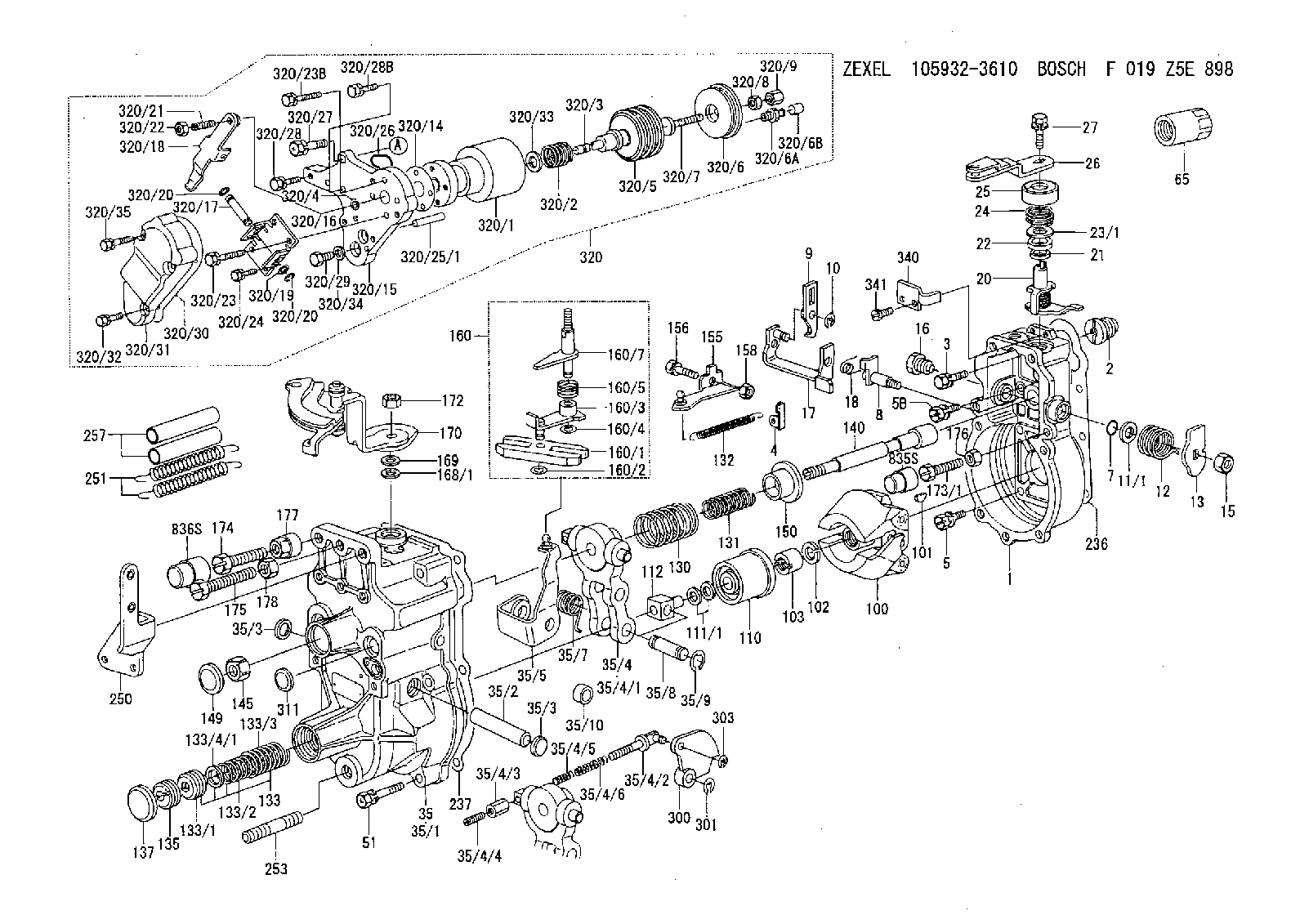
| 1. | [1] | 159200-5020 | GOVERNOR HOUSING |
| 2. | [1] | 154007-0200 | ADAPTOR |
| 3. | [1] | 020018-1840 | BLEEDER SCREW M8P1.25L18 |
| 4. | [1] | 159232-2620 | PLATE |
| 5. | [5] | 029010-6810 | BLEEDER SCREW |
| 5B. | [1] | 020106-1640 | BLEEDER SCREW M6P1.0L14 |
| 7. | [1] | 139710-0200 | O-RING |
| 8. | [1] | 159205-2321 | LEVER SHAFT |
| 9. | [1] | 159202-7800 | CONTROL LEVER |
| 10. | [1] | 016010-0810 | LOCKING WASHER |
| 11/1. | [0] | 029311-0220 | SHIM D18&10.3T0.2 |
| 11/1. | [0] | 029311-0230 | SHIM D18&10.3T0.5 |
| 11/1. | [0] | 029311-0430 | SHIM D18&10.3T0.30 |
| 11/1. | [0] | 029311-0440 | SHIM D18&10.3T0.40 |
| 11/1. | [0] | 029311-0450 | SHIM D18&10.3T0.25 |
| 11/1. | [0] | 029311-0460 | SHIM D18&10.3T0.35 |
| 11/1. | [0] | 139410-3300 | SHIM D18&10.3T0.6 |
| 11/1. | [0] | 139410-3400 | SHIM D18&10.3T0.8 |
| 11/1. | [0] | 139410-3500 | SHIM D18&10.3T0.9 |
| 12. | [1] | 159215-0000 | COILED SPRING |
| 13. | [1] | 159242-6601 | CONTROL LEVER |
| 15. | [1] | 013020-8040 | UNION NUT M8P1.25H7 |
| 16. | [1] | 159237-5500 | CAPSULE |
| 17. | [1] | 159202-5220 | CONTROL LEVER |
| 18. | [1] | 159215-0300 | COILED SPRING |
| 20. | [1] | 159291-0320 | CONTROL LEVER |
| 21. | [1] | 029311-0210 | SHIM D14&10.1T1 |
| 22. | [1] | 139610-0700 | PACKING RING |
| 23/1. | [0] | 139410-3800 | SHIM D22&10.2T0.2 |
| 23/1. | [0] | 139410-3900 | SHIM D22&10.2T0.3 |
| 23/1. | [0] | 139410-4000 | SHIM D22&10.2T0.4 |
| 23/1. | [0] | 139410-4100 | SHIM D22&10.2T0.6 |
| 23/1. | [0] | 139410-4200 | SHIM D22&10.2T0.8 |
| 24. | [1] | 159215-4200 | COILED SPRING |
| 25. | [1] | 159235-5800 | CAP |
| 26. | [1] | 159291-1620 | CONTROL LEVER |
| 27. | [1] | 020006-1240 | BLEEDER SCREW M6P1L12 4T |
| 35. | [1] | 159255-5020 | GOVERNOR COVER |
| 35/1. | [1] | 159301-6520 | GOVERNOR COVER |
| 35/2. | [1] | 159205-0400 | LEVER SHAFT |
| 35/3. | [2] | 159237-0200 | CAPSULE |
| 35/3. | [2] | 159237-0200 | CAPSULE |
| 35/4. | [1] | 159253-2220 | TENSIONING LEVER |
| 35/4/1. | [1] | 159203-1720 | TENSIONING LEVER |
| 35/4/2. | [1] | 159204-5021 | RACK |
| 35/4/3. | [1] | 159233-0300 | UNION NUT |
| 35/4/4. | [1] | 159234-0300 | FLAT-HEAD SCREW |
| 35/4/5. | [1] | 159216-0000 | COILED SPRING |
| 35/4/6. | [1] | 159216-0100 | COILED SPRING |
| 35/5. | [1] | 159203-6120 | GUIDE LEVER |
| 35/7. | [1] | 159215-1701 | COILED SPRING |
| 35/8. | [1] | 159231-1300 | BEARING PIN |
| 35/9. | [2] | 016010-0610 | LOCKING WASHER |
| 35/10. | [1] | 159238-2900 | BUSHING |
| 51. | [7] | 020106-3840 | BLEEDER SCREW |
| 65. | [1] | 155404-5700 | CAP |
| 100. | [1] | 154101-0420 | FLYWEIGHT ASSEMBLY |
| 101. | [1] | 025803-1610 | WOODRUFF KEY |
| 102. | [1] | 029321-2020 | LOCKING WASHER |
| 103. | [1] | 029231-2030 | UNION NUT |
| 110. | [1] | 154123-2320 | SLIDING PIECE |
| 111/1. | [0] | 029311-0010 | SHIM D14&10.1T0.2 |
| 111/1. | [0] | 029311-0180 | SHIM D14&10.1T0.3 |
| 111/1. | [0] | 029311-0190 | SHIM D14&10.1T0.40 |
| 111/1. | [0] | 029311-0210 | SHIM D14&10.1T1 |
| 111/1. | [0] | 139410-0000 | SHIM D14.0&10.1T0.5 |
| 111/1. | [0] | 139410-0100 | SHIM D14.0&10.1T1.5 |
| 111/1. | [0] | 139410-3000 | SHIM D14&10.1T2.0 |
| 111/1. | [0] | 139410-3100 | SHIM D14&10.1T3.0 |
| 111/1. | [0] | 139410-3200 | SHIM D14&10.1T4.0 |
| 112. | [1] | 159236-0200 | TERMINAL STUD |
| 130. | [1] | 159210-1800 | GOVERNOR SPRING |
| 131. | [1] | 159211-3700 | GOVERNOR SPRING |
| 132. | [1] | 159214-0100 | COILED SPRING |
| 133. | [1] | 159212-8220 | SPRING PACK |
| 133/1. | [1] | 159234-5602 | GUIDE SLEEVE |
| 133/2. | [1] | 159212-5000 | COILED SPRING |
| 133/3. | [1] | 159212-5700 | COILED SPRING |
| 133/4/1. | [0] | 029310-9240 | SHIM D11.9&9T0.1 |
| 133/4/1. | [0] | 029310-9250 | SHIM D11.9&9T0.2 |
| 133/4/1. | [0] | 029310-9260 | SHIM D11.9&9T0.25 |
| 133/4/1. | [0] | 029310-9270 | SHIM D11.9&9T1.0 |
| 133/4/1. | [0] | 139409-0100 | SHIM D11.9&9T0.3 |
| 133/4/1. | [0] | 139409-0200 | SHIM D11.9&9T0.5 |
| 133/4/1. | [0] | 139409-0300 | SHIM D11.5&9T0.8 |
| 135. | [1] | 159248-2700 | FLAT-HEAD SCREW |
| 137. | [1] | 159237-5300 | CAPSULE |
| 140. | [1] | 159205-2101 | LEVER SHAFT |
| 145. | [1] | 159233-5700 | UNION NUT |
| 149. | [1] | 159237-5400 | CAPSULE |
| 150. | [1] | 159235-5300 | SLOTTED WASHER |
| 155. | [1] | 159204-7720 | STRAP |
| 156. | [1] | 159233-0520 | BLEEDER SCREW |
| 158. | [1] | 013020-5240 | UNION NUT M5P0.8H4 |
| 160. | [1] | 159252-0821 | LEVER GROUP |
| 160/1. | [1] | 159202-2200 | CONTROL LEVER |
| 160/2. | [1] | 016010-0810 | LOCKING WASHER |
| 160/3. | [1] | 159202-2120 | CONTROL LEVER |
| 160/4. | [1] | 016010-0810 | LOCKING WASHER |
| 160/5. | [1] | 159215-2301 | COILED SPRING |
| 160/7. | [1] | 159205-2222 | LEVER SHAFT |
| 168/1. | [0] | 029311-0640 | SHIM D26.0&10.2T0.95 |
| 168/1. | [0] | 029311-0650 | SHIM D26.0&10.2T0.20 |
| 168/1. | [0] | 029311-0660 | SHIM D26.0&10.2T0.25 |
| 168/1. | [0] | 029311-0670 | SHIM D26.0&10.2T0.30 |
| 168/1. | [0] | 029311-0680 | SHIM D26.0&10.2T0.35 |
| 168/1. | [0] | 029311-0690 | SHIM D26.0&10.2T0.40 |
| 168/1. | [0] | 029311-0700 | SHIM D26.0&10.2T0.50 |
| 168/1. | [0] | 139410-1400 | SHIM D26&10.2T0.7 |
| 168/1. | [0] | 139410-1500 | SHIM D26&10.2T0.9 |
| 168/1. | [0] | 139410-1600 | SHIM D26&10.2T0.8 |
| 168/1. | [0] | 139410-2700 | SHIM D26&10.2T0.6 |
| 169. | [1] | 159238-4300 | SHIM |
| 170. | [1] | 159263-4421 | CONTROL LEVER |
| 172. | [1] | 013020-8040 | UNION NUT M8P1.25H7 |
| 173/1. | [1] | 139006-3500 | BLEEDER SCREW M6P1.0L33 |
| 173/1. | [1] | 139006-3700 | BLEEDER SCREW M6P1.0L34 |
| 173/1. | [1] | 139006-3800 | BLEEDER SCREW M6P1.0L35 |
| 173/1. | [1] | 139006-3900 | BLEEDER SCREW M6P1.0L36 |
| 173/1. | [1] | 139006-5300 | BLEEDER SCREW M6P1.0L31 |
| 173/1. | [1] | 139006-5400 | BLEEDER SCREW M6P1.0L32 |
| 173/1. | [1] | 155615-2500 | BLEEDER SCREW M6P1.0L37 |
| 174. | [1] | 154010-7200 | BLEEDER SCREW M8P1.25L62 |
| 174B. | [1] | 154010-8100 | BLEEDER SCREW M8P1.25L65 |
| 175. | [1] | 154010-8100 | BLEEDER SCREW M8P1.25L65 |
| 176. | [1] | 159225-8600 | UNION NUT |
| 177. | [1] | 154011-2300 | UNION NUT |
| 178. | [1] | 154011-2800 | UNION NUT |
| 236. | [1] | 154390-0000 | GASKET |
| 237. | [1] | 159238-3100 | GASKET |
| 250. | [1] | 159221-2920 | BRACKET |
| 251. | [2] | 154317-8800 | COILED SPRING |
| 253. | [1] | 139010-0000 | STUD |
| 257. | [2] | 154156-0900 | TUBE |
| 300. | [1] | 159287-3100 | CAM PLATE |
| 301. | [1] | 016010-0840 | LOCKING WASHER |
| 303. | [1] | 016010-0540 | LOCKING WASHER |
| 311. | [1] | 159237-0200 | CAPSULE |
| 320. | [1] | 155424-7120 | ANEROID CAPSULE |
| 320/1. | [1] | 155424-6520 | DIAPHRAGM HOUSING |
| 320/2. | [1] | 155423-8200 | COILED SPRING |
| 320/3. | [1] | 155423-0300 | STOP PIN |
| 320/4. | [1] | 016020-1220 | LOCKING WASHER |
| 320/5. | [1] | 155403-3021 | BELLOWS |
| 320/6. | [1] | 155423-2000 | COVER |
| 320/6A. | [1] | 139805-0000 | JOINT CONNECTION |
| 320/6B. | [1] | 155424-0300 | CAP |
| 320/7. | [1] | 155423-1500 | SCREW PLUG |
| 320/8. | [1] | 029240-6010 | UNION NUT M6P1.0H5* |
| 320/9. | [1] | 154035-1600 | CAP NUT |
| 320/14. | [1] | 154390-2700 | GASKET |
| 320/15. | [1] | 155423-0700 | SPACER BUSHING |
| 320/16. | [1] | 155423-0800 | PLATE |
| 320/17. | [1] | 155423-0900 | LEVER SHAFT |
| 320/18. | [1] | 155423-1000 | CONTROL LEVER |
| 320/19. | [2] | 029310-4060 | SHIM |
| 320/20. | [2] | 016010-0440 | LOCKING WASHER |
| 320/20. | [2] | 016010-0440 | LOCKING WASHER |
| 320/21. | [1] | 155423-1100 | FLAT-HEAD SCREW |
| 320/22. | [1] | 013020-6010 | UNION NUT |
| 320/23. | [2] | 020105-2540 | BLEEDER SCREW |
| 320/23B. | [2] | 020105-2040 | BLEEDER SCREW M5P0.8L20 |
| 320/24. | [2] | 020105-0840 | BLEEDER SCREW M5P0.5L8 |
| 320/25/1. | [1] | 155423-1200 | STOP PIN L102 |
| 320/25/1. | [1] | 155424-4900 | STOP PIN L95 |
| 320/25/1. | [1] | 155424-5000 | STOP PIN L96 |
| 320/25/1B. | [1] | 155423-1300 | STOP PIN L102.5 |
| 320/25/1C. | [1] | 155423-1400 | STOP PIN L103 |
| 320/25/1D. | [1] | 155423-7600 | STOP PIN L103.5 |
| 320/25/1E. | [1] | 155423-7700 | STOP PIN L104 |
| 320/25/1F. | [1] | 155423-8700 | STOP PIN L97 |
| 320/25/1G. | [1] | 155423-8800 | STOP PIN L98 |
| 320/25/1H. | [1] | 155423-8900 | STOP PIN L99 |
| 320/25/1I. | [1] | 155423-9000 | STOP PIN L100 |
| 320/25/1J. | [1] | 155423-9100 | STOP PIN L101 |
| 320/26. | [1] | 159226-4500 | SPACER RING |
| 320/27. | [1] | 020118-2540 | BLEEDER SCREW |
| 320/28. | [2] | 020106-2240 | BLEEDER SCREW |
| 320/28B. | [1] | 020106-1840 | BLEEDER SCREW M6P1L18 |
| 320/29. | [1] | 139006-1800 | BLEEDER SCREW |
| 320/30. | [1] | 154390-2800 | GASKET |
| 320/31. | [1] | 155423-0500 | COVER |
| 320/32. | [2] | 020105-1240 | BLEEDER SCREW M5P0.8L12 |
| 320/33. | [1] | 029311-2060 | SHIM D22&12.5T0.5 |
| 320/34. | [1] | 026506-1040 | GASKET D9.9&6.2T1 |
| 320/35. | [2] | 020105-2540 | BLEEDER SCREW |
| 340. | [1] | 159245-8300 | PLATE |
| 341. | [2] | 020104-1040 | BLEEDER SCREW |
| 835S. | [1] | 154062-1900 | CAP D12L24 |
| 836S. | [1] | 154062-1700 | CAP D20L32 |
Include in #1:
101401-7780
as GOVERNOR
Cross reference number
Zexel num
Bosch num
Firm num
Name
Information:
9-1345. Assemble screw to secure end plate of crankcase breather to the oil sump.Fig. 9-1346. Turn the engine over so that the cylinders are in the upward vertical position.
9-1357. Secure front vertical plate to cylinder. Secure fuel pipe for flame-type heater plug by clip.Fig. 9-135
9-1368. Position air cowling base, screw in central bolt and fit two washers. (Example: F5L)Fig. 9-136
9-1379. Install the oil cooler fitted with a a new rubber O-ring to seal against the lower part of the air cowling. Tighten the pipe unions.Fig. 9-137
9-13810. Fit bolts with washers for oil cooler.Fig. 9-138
9-13911. Secure exhaust air baffle.Fig. 9-139
9-14012. Fit rear vertical plate.Fig. 9-140
9-14113. Fit cooling blower to front-end cover.Fig. 9-141
9-14214. Position the upper cover plate on the cylinder heads.Fig. 9-14215. Connect fuel delivery lines, fitting new rubber mounting strip and new rubber sleeves.
9-14316. Connect the leak-off lines between the injectors and from one of the injectors to the injection pump. Assemble the long hollow screw in cylinder 1 and plug it to prevent the ingress of dirt.Fig. 9-143
9-14417. If the engine has a flame-type heater system, mount the solenoid valve on the front vertical plate.Fig. 9-14418. Install bracket mounting new fuel and lubricating oil filters and connect the fuel lines, fitting new gaskets.
9-14518.1. See Fig. 9-145 for F3L.
9-14618.2. See Fig. 9-146 for F4/6L.
9-14719. Install temperature sensors/contactors in cylinder heads. Starting Fig. 9-147 the following notes are applicable.
9-148 Sensor and contactor differ by their length. Fig. 9-148 shows sensor at left and contactor at right. Important:The direct-injection (D) and two-stage combustion (W) engines have contact makers (switches) of different temperature limits:D = 150° CW = 170° C
9-149 Cylinder numbering.Fig. 9-149The temperature sensor is secured to pickup point 1. A second sensor or a contactor is secured to point 2.
9-15020. Hook in the air cowling at the top and close at the bottom.Fig. 9-150
9-15121. Fit a new gasket in the oil filler cap. Replace the rubber gasket by a cork gasket.Fig. 9-15122. Close the oil filler; insert oil dipstick.
9-15223. Where an extra-long oil filler neck and dipstick guide have been provided, install filler neck with new O-ring in front-end cover and secure to cooling blower. Install dipstick guide.Fig. 9-152
9-15324. If the engine is fitted with an air compressor the oil return hole in the front cover plate must be left open. If the engine is not fitted with an air compressor a plug coated with jointing compound should be screwed into the oil return hole.Fig. 9-153 The next three operations apply only if the engine is fitted with an air compressor.
9-15425. Coat a new rubber O-seal with grease and stick it in position on the bracket of the air compressor.Fig. 9-154
9-15526. Mount the air compressor with bracket on the front cover plate.Fig. 9-155
9-15627. Install the high-pressure oil line, fitted with new gaskets, running from the oil gallery to the air compressor and tighten the female screws.Fig. 9-156
9-15728. Install new gaskets for the induction and exhaust manifolds with the flat end upwards.Fig. 9-157 On engines of more recent design, fit