Information governor
BOSCH
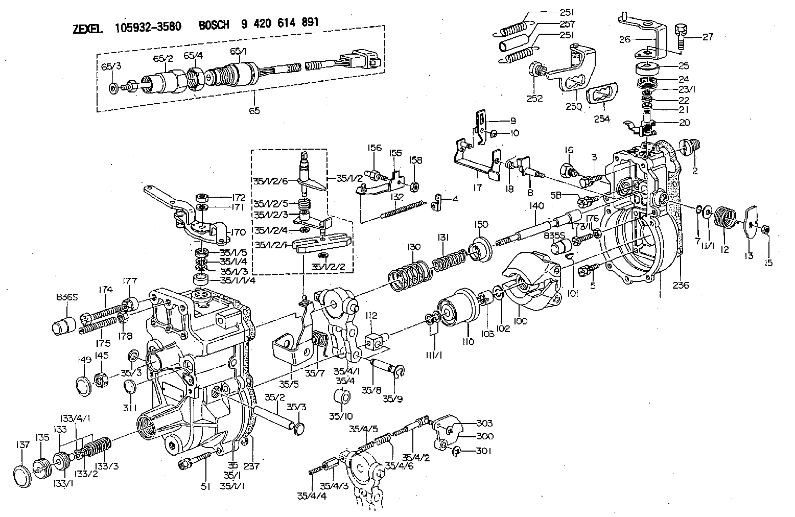
9 420 614 891
9420614891
ZEXEL
105932-3580
1059323580
NISSAN-DIESEL
19101Z9000
19101z9000
Rating:
Scheme ###:
| 1. | [1] | 159200-7220 | GOVERNOR HOUSING |
| 2. | [1] | 154007-0200 | ADAPTOR |
| 3. | [1] | 020018-1840 | BLEEDER SCREW M8P1.25L18 |
| 4. | [1] | 159232-2620 | PLATE |
| 5. | [5] | 029010-6810 | BLEEDER SCREW |
| 5B. | [1] | 020106-1640 | BLEEDER SCREW M6P1.0L14 |
| 7. | [1] | 016530-1010 | O-RING |
| 8. | [1] | 159205-2321 | LEVER SHAFT |
| 9. | [1] | 159202-8920 | CONTROL LEVER |
| 10. | [1] | 016010-0810 | LOCKING WASHER |
| 11/1. | [0] | 029311-0220 | SHIM D18&10.3T0.2 |
| 11/1. | [0] | 029311-0230 | SHIM D18&10.3T0.5 |
| 11/1. | [0] | 029311-0430 | SHIM D18&10.3T0.30 |
| 11/1. | [0] | 029311-0440 | SHIM D18&10.3T0.40 |
| 11/1. | [0] | 029311-0450 | SHIM D18&10.3T0.25 |
| 11/1. | [0] | 029311-0460 | SHIM D18&10.3T0.35 |
| 11/1. | [0] | 139410-3300 | SHIM D18&10.3T0.6 |
| 11/1. | [0] | 139410-3400 | SHIM D18&10.3T0.8 |
| 11/1. | [0] | 139410-3500 | SHIM D18&10.3T0.9 |
| 12. | [1] | 159215-0000 | COILED SPRING |
| 13. | [1] | 159242-6601 | CONTROL LEVER |
| 15. | [1] | 013020-8040 | UNION NUT M8P1.25H7 |
| 16. | [1] | 159237-5500 | CAPSULE |
| 17. | [1] | 159202-5320 | CONTROL LEVER |
| 18. | [1] | 159215-0300 | COILED SPRING |
| 20. | [1] | 159242-0220 | CONTROL LEVER |
| 21. | [1] | 029311-0210 | SHIM D14&10.1T1 |
| 22. | [1] | 139610-0400 | PACKING RING |
| 23/1. | [0] | 139411-0700 | SHIM D22&11T0.7 |
| 23/1. | [0] | 153305-0100 | SHIM D22&11T0.5 |
| 23/1. | [0] | 153305-0200 | SHIM D22&11T0.4 |
| 23/1. | [0] | 153305-0300 | SHIM D22&11T0.3 |
| 23/1. | [0] | 153305-0400 | SHIM D22&11T0.25 |
| 23/1. | [0] | 153305-0500 | SHIM D22&11T1.0 |
| 23/1. | [0] | 153305-0600 | SHIM D22&11T1.1 |
| 23/1. | [0] | 153305-0700 | SHIM D22&11T2.0 |
| 23/1. | [0] | 153305-1300 | SHIM D22&11T0.951 |
| 23/1. | [0] | 153305-1400 | SHIM D22&11T0.95 |
| 24. | [1] | 159215-2000 | COILED SPRING |
| 25. | [1] | 159235-5800 | CAP |
| 26. | [1] | 159291-5720 | CONTROL LEVER |
| 27. | [1] | 020006-1640 | BLEEDER SCREW M6P1L16 4T |
| 35. | [1] | 159255-4420 | GOVERNOR COVER |
| 35/1. | [1] | 159301-6120 | GOVERNOR COVER |
| 35/1/1. | [1] | 159301-5920 | GOVERNOR COVER |
| 35/1/1/4. | [1] | 159230-2800 | BUSHING |
| 35/1/2. | [1] | 159252-4420 | LEVER GROUP |
| 35/1/2/1. | [1] | 159202-2200 | CONTROL LEVER |
| 35/1/2/2. | [1] | 016010-0810 | LOCKING WASHER |
| 35/1/2/3. | [1] | 159202-2120 | CONTROL LEVER |
| 35/1/2/4. | [1] | 016010-0810 | LOCKING WASHER |
| 35/1/2/5. | [1] | 159215-2301 | COILED SPRING |
| 35/1/2/6. | [1] | 159205-6320 | LEVER SHAFT |
| 35/1/3. | [1] | 139411-0600 | SHIM |
| 35/1/4. | [1] | 159238-3000 | LOCKING WASHER |
| 35/1/5. | [1] | 029621-0080 | PACKING RING |
| 35/2. | [1] | 159205-0400 | LEVER SHAFT |
| 35/3. | [2] | 159237-0200 | CAPSULE |
| 35/3. | [2] | 159237-0200 | CAPSULE |
| 35/4. | [1] | 159253-2220 | TENSIONING LEVER |
| 35/4/1. | [1] | 159203-1720 | TENSIONING LEVER |
| 35/4/2. | [1] | 159204-5021 | RACK |
| 35/4/3. | [1] | 159233-0300 | UNION NUT |
| 35/4/4. | [1] | 159234-0300 | FLAT-HEAD SCREW |
| 35/4/5. | [1] | 159216-0000 | COILED SPRING |
| 35/4/6. | [1] | 159216-0100 | COILED SPRING |
| 35/5. | [1] | 159203-6620 | GUIDE LEVER |
| 35/7. | [1] | 159215-1701 | COILED SPRING |
| 35/8. | [1] | 159231-1300 | BEARING PIN |
| 35/9. | [2] | 016010-0610 | LOCKING WASHER |
| 35/10. | [1] | 159238-2900 | BUSHING |
| 51. | [7] | 020106-3840 | BLEEDER SCREW |
| 65. | [1] | 154612-8120 | RACK SENSOR ASSY |
| 65/1. | [1] | 407945-0440 | RACK SENSOR |
| 65/2. | [1] | 154614-7100 | JOINT CONNECTION |
| 65/3. | [1] | 139406-0800 | SHIM |
| 65/4. | [1] | 154614-1900 | UNION NUT |
| 100. | [1] | 154100-9520 | FLYWEIGHT ASSEMBLY |
| 101. | [1] | 025803-1610 | WOODRUFF KEY |
| 102. | [1] | 029321-2020 | LOCKING WASHER |
| 103. | [1] | 029231-2030 | UNION NUT |
| 110. | [1] | 154123-2320 | SLIDING PIECE |
| 111/1. | [0] | 029311-0010 | SHIM D14&10.1T0.2 |
| 111/1. | [0] | 029311-0180 | SHIM D14&10.1T0.3 |
| 111/1. | [0] | 029311-0190 | SHIM D14&10.1T0.40 |
| 111/1. | [0] | 029311-0210 | SHIM D14&10.1T1 |
| 111/1. | [0] | 139410-0000 | SHIM D14.0&10.1T0.5 |
| 111/1. | [0] | 139410-0100 | SHIM D14.0&10.1T1.5 |
| 111/1. | [0] | 139410-3000 | SHIM D14&10.1T2.0 |
| 111/1. | [0] | 139410-3100 | SHIM D14&10.1T3.0 |
| 111/1. | [0] | 139410-3200 | SHIM D14&10.1T4.0 |
| 112. | [1] | 159236-0200 | TERMINAL STUD |
| 130. | [1] | 159210-5300 | GOVERNOR SPRING |
| 131. | [1] | 159211-7100 | GOVERNOR SPRING |
| 132. | [1] | 159214-0100 | COILED SPRING |
| 133. | [1] | 159219-3220 | SPRING PACK |
| 133/1. | [1] | 159234-5602 | GUIDE SLEEVE |
| 133/2. | [1] | 159212-8900 | COILED SPRING |
| 133/3. | [1] | 159219-1400 | COILED SPRING |
| 133/4/1. | [0] | 029310-9240 | SHIM D11.9&9T0.1 |
| 133/4/1. | [0] | 029310-9250 | SHIM D11.9&9T0.2 |
| 133/4/1. | [0] | 029310-9260 | SHIM D11.9&9T0.25 |
| 133/4/1. | [0] | 029310-9270 | SHIM D11.9&9T1.0 |
| 133/4/1. | [0] | 139409-0100 | SHIM D11.9&9T0.3 |
| 133/4/1. | [0] | 139409-0200 | SHIM D11.9&9T0.5 |
| 133/4/1. | [0] | 139409-0300 | SHIM D11.5&9T0.8 |
| 135. | [1] | 159248-2700 | FLAT-HEAD SCREW |
| 137. | [1] | 159237-5300 | CAPSULE |
| 140. | [1] | 159205-2101 | LEVER SHAFT |
| 145. | [1] | 159233-5700 | UNION NUT |
| 149. | [1] | 159237-5400 | CAPSULE |
| 150. | [1] | 159235-5300 | SLOTTED WASHER |
| 155. | [1] | 159204-8521 | STRAP |
| 156. | [1] | 159233-0700 | BLEEDER SCREW |
| 158. | [1] | 013020-5240 | UNION NUT M5P0.8H4 |
| 170. | [1] | 159295-2720 | CONTROL LEVER |
| 171. | [1] | 014110-8440 | LOCKING WASHER |
| 172. | [1] | 013020-8040 | UNION NUT M8P1.25H7 |
| 173/1. | [1] | 139006-7700 | BLEEDER SCREW |
| 173/1. | [1] | 139006-7800 | BLEEDER SCREW |
| 173/1. | [1] | 139006-7900 | BLEEDER SCREW |
| 173/1. | [1] | 139006-8000 | BLEEDER SCREW |
| 173/1. | [1] | 139006-8100 | BLEEDER SCREW |
| 173/1. | [1] | 139006-8200 | BLEEDER SCREW |
| 173/1. | [1] | 139006-8300 | BLEEDER SCREW |
| 174. | [1] | 154010-7200 | BLEEDER SCREW M8P1.25L62 |
| 174B. | [1] | 154010-8100 | BLEEDER SCREW M8P1.25L65 |
| 175. | [1] | 154013-5200 | FLAT-HEAD SCREW |
| 176. | [1] | 159233-7500 | UNION NUT |
| 177. | [1] | 154011-2300 | UNION NUT |
| 178. | [1] | 013020-8040 | UNION NUT M8P1.25H7 |
| 236. | [1] | 154390-1300 | GASKET |
| 237. | [1] | 159238-3100 | GASKET |
| 250. | [1] | 159223-7220 | BRACKET |
| 251. | [2] | 154339-9100 | COILED SPRING |
| 251. | [2] | 154339-9100 | COILED SPRING |
| 252. | [2] | 159248-4100 | BLEEDER SCREW |
| 254. | [1] | 159232-3200 | PLAIN WASHER |
| 257. | [2] | 154156-0500 | TUBE |
| 300. | [1] | 159289-9300 | CAM PLATE |
| 301. | [1] | 016010-0840 | LOCKING WASHER |
| 303. | [1] | 016010-0540 | LOCKING WASHER |
| 311. | [1] | 159237-0200 | CAPSULE |
| 835S. | [1] | 154062-1900 | CAP D12L24 |
| 836S. | [1] | 154062-1700 | CAP D20L32 |
Cross reference number
Zexel num
Bosch num
Firm num
Name
105932-3580
19101Z9000 NISSAN-DIESEL
GOVERNOR
K 14JK MECHANICAL GOVERNOR GOV RLD GOV
K 14JK MECHANICAL GOVERNOR GOV RLD GOV
Information:
Removing And Fitting A Starter Gear Ring
It is assumed that the flywheel is dismantled.Removing:
6-1Cut through the starter gear ring with a hard chisel and remove.Fig. 6-1Refitting:
1. Heat the starter gear ring to a temperature of 120 deg. C. Place the starter gear ring with the bevelled side of the teeth facing away from flywheel.
6-22. Locate the starter gear ring on the flywheel and tap it into position so that it seats against the shoulder.Fig. 6-2Removing And Fitting A Radial Sealing Ring On The Flywheel Side
It is assumed that the flywheel has been dismantled. Removing:
6-3Apply puller No. 142700 and draw off radial sealing ring.Fig. 6-3Refitting:
6-41. Mount guide-piece of device onto crankshaft.Fig. 6-4
6-52. Lightly grease the sealing lip of the new radial seal. Place seal on guide-piece with lip facing towards crankcase and press in with device No. 142530.Fig. 6-5 Inspect crankshaft in the zone of radial seal contact. If a friction groove has been formed by the radial seal, displace the complete cover by adding gaskets accordingly.Dismantling, Installing And Sealing The Cover On The Flywheel Side (As from 3-cylinder engine)
The flywheel has already been removed.Dismantling:
1. Remove the bolts in the oil sump securing the cover on the flywheel side and the bolts securing the cover to the crankcase. Remove cover and gasket. Renew radial sealing ring. Inspect crankshaft in the zone of radial seal contact. If a friction groove has been formed by the radial seal, displace the latter in the cover.Installing:
6-112. Adhere new gasket to crankcase. Trim off the portion of gasket projecting beyond the joint surface of the sump. Fig. 6-113. Apply coat of Deutz DW 48 jointing compound to the oil sump gasket in the region of the cover.
6-124. Press new radial seal into the rear cover so that the outside surface is flush (arrow).Fig. 6-12 Prior to fitting, heat cover "hand-warm" and coat radial seal with jointing compound.
6-135. Place cover in position. Lightly pretighten cover bolts in crankcase. Fully tighten sump bolts in cover, then fully tighten bolts in crankcase.Fig. 6-13Exploded Views