Information governor
BOSCH
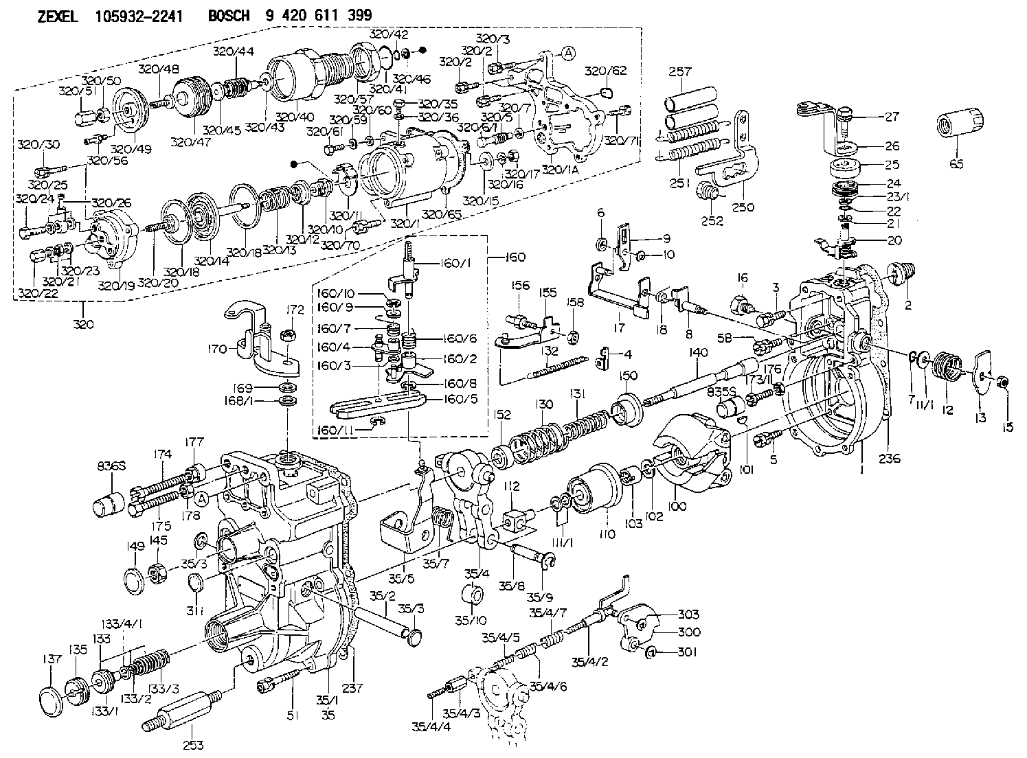
9 420 611 399
9420611399
ZEXEL
105932-2241
1059322241
ISUZU
8971738771
8971738771
Rating:
Scheme ###:
| 1. | [1] | 159200-4720 | GOVERNOR HOUSING |
| 2. | [1] | 154007-0200 | ADAPTOR |
| 3. | [1] | 020018-1840 | BLEEDER SCREW M8P1.25L18 |
| 4. | [1] | 159232-1600 | PLATE |
| 5. | [5] | 029010-6810 | BLEEDER SCREW |
| 5B. | [1] | 020106-1640 | BLEEDER SCREW M6P1.0L14 |
| 6. | [1] | 159242-0600 | BUSHING |
| 7. | [1] | 016530-1010 | O-RING |
| 8. | [1] | 159205-2321 | LEVER SHAFT |
| 9. | [1] | 159202-5601 | CONTROL LEVER |
| 10. | [1] | 016010-0810 | LOCKING WASHER |
| 11/1. | [0] | 029311-0220 | SHIM D18&10.3T0.2 |
| 11/1. | [0] | 029311-0230 | SHIM D18&10.3T0.5 |
| 11/1. | [0] | 029311-0430 | SHIM D18&10.3T0.30 |
| 11/1. | [0] | 029311-0440 | SHIM D18&10.3T0.40 |
| 11/1. | [0] | 029311-0450 | SHIM D18&10.3T0.25 |
| 11/1. | [0] | 029311-0460 | SHIM D18&10.3T0.35 |
| 11/1. | [0] | 139410-3400 | SHIM D18&10.3T0.8 |
| 11/1. | [0] | 139410-3500 | SHIM D18&10.3T0.9 |
| 12. | [1] | 159215-0000 | COILED SPRING |
| 13. | [1] | 159242-6601 | CONTROL LEVER |
| 15. | [1] | 013020-8040 | UNION NUT M8P1.25H7 |
| 16. | [1] | 159237-5500 | CAPSULE |
| 17. | [1] | 159202-5220 | CONTROL LEVER |
| 18. | [1] | 159215-1600 | COILED SPRING |
| 20. | [1] | 159291-0420 | CONTROL LEVER |
| 22. | [1] | 029631-0030 | O-RING &9.8W2.3 |
| 23/1. | [0] | 139410-1300 | SHIM D20.8&10.2T0.3 |
| 23/1. | [0] | 139410-1700 | SHIM D20.8&10.2T0.2 |
| 23/1. | [0] | 139410-1800 | SHIM D20.8&10.2T0.4 |
| 23/1. | [0] | 139410-2800 | SHIM D20.8&10.2T0.6 |
| 23/1. | [0] | 139410-3700 | SHIM D20.8&10.2T0.9 |
| 24. | [1] | 159215-4200 | COILED SPRING |
| 25. | [1] | 159235-6500 | CAP |
| 26. | [1] | 159249-8620 | CONTROL LEVER |
| 27. | [1] | 020006-1240 | BLEEDER SCREW M6P1L12 4T |
| 35. | [1] | 159250-1320 | GOVERNOR COVER |
| 35/1. | [1] | 159201-7020 | GOVERNOR COVER |
| 35/2. | [1] | 159205-0400 | LEVER SHAFT |
| 35/3. | [2] | 159237-0200 | CAPSULE |
| 35/3. | [2] | 159237-0200 | CAPSULE |
| 35/4. | [1] | 159253-2720 | TENSIONING LEVER |
| 35/4/2. | [1] | 159204-6022 | RACK |
| 35/4/3. | [1] | 159233-0300 | UNION NUT |
| 35/4/4. | [1] | 159234-0300 | FLAT-HEAD SCREW |
| 35/4/5. | [1] | 159216-0000 | COILED SPRING |
| 35/4/6. | [1] | 159216-0100 | COILED SPRING |
| 35/4/7. | [1] | 159216-0700 | COILED SPRING |
| 35/5. | [1] | 159203-6120 | GUIDE LEVER |
| 35/7. | [1] | 159215-1701 | COILED SPRING |
| 35/8. | [1] | 159231-1300 | BEARING PIN |
| 35/9. | [2] | 016010-0610 | LOCKING WASHER |
| 35/10. | [1] | 159238-2900 | BUSHING |
| 51. | [7] | 020106-3840 | BLEEDER SCREW |
| 65. | [1] | 155404-5700 | CAP |
| 100. | [1] | 154100-9520 | FLYWEIGHT ASSEMBLY |
| 101. | [1] | 025803-1610 | WOODRUFF KEY |
| 102. | [1] | 029321-2020 | LOCKING WASHER |
| 103. | [1] | 029231-2030 | UNION NUT |
| 110. | [1] | 154123-2320 | SLIDING PIECE |
| 111/1. | [0] | 029311-0010 | SHIM D14&10.1T0.2 |
| 111/1. | [0] | 029311-0180 | SHIM D14&10.1T0.3 |
| 111/1. | [0] | 029311-0190 | SHIM D14&10.1T0.40 |
| 111/1. | [0] | 029311-0210 | SHIM D14&10.1T1 |
| 111/1. | [0] | 139410-0000 | SHIM D14.0&10.1T0.5 |
| 111/1. | [0] | 139410-0100 | SHIM D14.0&10.1T1.5 |
| 111/1. | [0] | 139410-3000 | SHIM D14&10.1T2.0 |
| 111/1. | [0] | 139410-3100 | SHIM D14&10.1T3.0 |
| 111/1. | [0] | 139410-3200 | SHIM D14&10.1T4.0 |
| 112. | [1] | 159236-0200 | TERMINAL STUD |
| 130. | [1] | 159210-1000 | GOVERNOR SPRING |
| 131. | [1] | 159211-1100 | GOVERNOR SPRING |
| 132. | [1] | 159214-0300 | COILED SPRING |
| 133. | [1] | 159212-3520 | SPRING PACK |
| 133/1. | [1] | 159234-5602 | GUIDE SLEEVE |
| 133/2. | [1] | 159212-3300 | COILED SPRING |
| 133/3. | [1] | 159212-3500 | COILED SPRING |
| 133/4/1. | [0] | 029310-9240 | SHIM D11.9&9T0.1 |
| 133/4/1. | [0] | 029310-9250 | SHIM D11.9&9T0.2 |
| 133/4/1. | [0] | 029310-9260 | SHIM D11.9&9T0.25 |
| 133/4/1. | [0] | 029310-9270 | SHIM D11.9&9T1.0 |
| 133/4/1. | [0] | 139409-0100 | SHIM D11.9&9T0.3 |
| 133/4/1. | [0] | 139409-0200 | SHIM D11.9&9T0.5 |
| 133/4/1. | [0] | 139409-0300 | SHIM D11.5&9T0.8 |
| 135. | [1] | 159248-2700 | FLAT-HEAD SCREW |
| 137. | [1] | 159237-5300 | CAPSULE |
| 140. | [1] | 159205-2101 | LEVER SHAFT |
| 145. | [1] | 159233-5700 | UNION NUT |
| 149. | [1] | 159237-5400 | CAPSULE |
| 150. | [1] | 159235-5300 | SLOTTED WASHER |
| 155. | [1] | 159204-5920 | STRAP |
| 156. | [1] | 159233-6020 | BLEEDER SCREW |
| 158. | [1] | 013020-5240 | UNION NUT M5P0.8H4 |
| 160. | [1] | 159252-2221 | LEVER GROUP |
| 160/1. | [1] | 159205-3711 | LEVER SHAFT |
| 160/2. | [1] | 159202-4810 | CONTROL LEVER |
| 160/3. | [1] | 029310-6030 | SHIM D11.5&6.2T0.2 |
| 160/4. | [1] | 159202-4520 | CONTROL LEVER |
| 160/5. | [1] | 159202-2200 | CONTROL LEVER |
| 160/6. | [1] | 159215-2301 | COILED SPRING |
| 160/7. | [1] | 159215-3900 | COILED SPRING |
| 160/8. | [1] | 016010-0810 | LOCKING WASHER |
| 160/9. | [1] | 014020-6140 | PLAIN WASHER |
| 160/10. | [1] | 016010-0610 | LOCKING WASHER |
| 160/11. | [1] | 016010-0810 | LOCKING WASHER |
| 168/1. | [0] | 139410-1200 | SHIM D26&10.2T0.3 |
| 168/1. | [0] | 139410-1900 | SHIM D26&10.2T0.2 |
| 168/1. | [0] | 139410-2000 | SHIM D26&10.2T0.4 |
| 168/1. | [0] | 139410-2400 | SHIM D26&10.2T0.35 |
| 168/1. | [0] | 139410-2500 | SHIM D26&10.2T0.25 |
| 168/1. | [0] | 139410-2900 | SHIM D26&10.2T0.6 |
| 169. | [1] | 139410-2100 | SHIM |
| 170. | [1] | 159264-3520 | CONTROL LEVER |
| 172. | [1] | 013020-8040 | UNION NUT M8P1.25H7 |
| 173/1. | [1] | 139006-3500 | BLEEDER SCREW M6P1.0L33 |
| 173/1. | [1] | 139006-3700 | BLEEDER SCREW M6P1.0L34 |
| 173/1. | [1] | 139006-3800 | BLEEDER SCREW M6P1.0L35 |
| 173/1. | [1] | 139006-3900 | BLEEDER SCREW M6P1.0L36 |
| 173/1. | [1] | 139006-5300 | BLEEDER SCREW M6P1.0L31 |
| 173/1. | [1] | 139006-5400 | BLEEDER SCREW M6P1.0L32 |
| 173/1. | [1] | 155615-2500 | BLEEDER SCREW M6P1.0L37 |
| 174. | [1] | 154010-7200 | BLEEDER SCREW M8P1.25L62 |
| 174B. | [1] | 154010-8100 | BLEEDER SCREW M8P1.25L65 |
| 175. | [1] | 154012-4700 | BLEEDER SCREW |
| 176. | [1] | 159225-8600 | UNION NUT |
| 177. | [1] | 154011-2300 | UNION NUT |
| 178. | [1] | 154011-3500 | UNION NUT |
| 236. | [1] | 154390-0000 | GASKET |
| 237. | [1] | 159238-3100 | GASKET |
| 250. | [1] | 159228-4920 | BRACKET |
| 251. | [2] | 159243-4800 | COILED SPRING |
| 252. | [1] | 159248-0200 | BLEEDER SCREW |
| 253. | [1] | 159248-0401 | BLEEDER SCREW |
| 257. | [2] | 154156-0500 | TUBE |
| 300. | [1] | 159285-4500 | CAM PLATE |
| 301. | [1] | 016010-0840 | LOCKING WASHER |
| 303. | [1] | 016010-0540 | LOCKING WASHER |
| 311. | [1] | 159237-0200 | CAPSULE |
| 320. | [1] | 154421-8321 | COMPENSATOR,MANIFOLD-PRES |
| 320/1. | [1] | 154413-5421 | DIAPHRAGM HOUSING |
| 320/1A. | [1] | 154413-5501 | SPACER BUSHING |
| 320/2. | [3] | 020106-2240 | BLEEDER SCREW |
| 320/2. | [3] | 020106-2240 | BLEEDER SCREW |
| 320/3. | [1] | 020118-3240 | BLEEDER SCREW |
| 320/5. | [1] | 159275-1400 | COILED SPRING |
| 320/6/1. | [1] | 159274-0120 | STOP PIN L125 |
| 320/6/1. | [1] | 159274-0220 | STOP PIN L127.50 |
| 320/6/1. | [1] | 159274-0320 | STOP PIN L128.00 |
| 320/6/1. | [1] | 159274-0420 | STOP PIN L127.00 |
| 320/6/1. | [1] | 159274-0520 | STOP PIN L126.00 |
| 320/6/1. | [1] | 159274-0620 | STOP PIN L129.00 |
| 320/6/1. | [1] | 159274-0720 | STOP PIN L128.50 |
| 320/6/1. | [1] | 159274-0820 | STOP PIN L125.50 |
| 320/6/1. | [1] | 159274-0920 | STOP PIN L126.50 |
| 320/6/1. | [1] | 159274-1120 | STOP PIN L119.5 |
| 320/6/1. | [1] | 159274-1320 | STOP PIN L120.5 |
| 320/6/1. | [1] | 159274-1420 | STOP PIN L121 |
| 320/6/1. | [1] | 159274-1520 | STOP PIN L121.5 |
| 320/6/1. | [1] | 159274-1620 | STOP PIN L122 |
| 320/6/1. | [1] | 159274-1720 | STOP PIN L122.5 |
| 320/6/1. | [1] | 159274-1820 | STOP PIN L123 |
| 320/6/1. | [1] | 159274-1920 | STOP PIN L123.5 |
| 320/6/1. | [1] | 159274-4220 | STOP PIN L129.5 |
| 320/6/1. | [1] | 159274-4320 | STOP PIN L130 |
| 320/6/1. | [1] | 159274-4420 | STOP PIN L130.5 |
| 320/6/1. | [1] | 159274-4520 | STOP PIN L131 |
| 320/6/1. | [1] | 159274-4620 | STOP PIN L131.5 |
| 320/6/1. | [1] | 159274-4720 | STOP PIN L132 |
| 320/6/1. | [1] | 159274-4820 | STOP PIN L132.5 |
| 320/6/1. | [1] | 159274-4920 | STOP PIN L133 |
| 320/6/1. | [1] | 159274-5020 | STOP PIN L133.5 |
| 320/7. | [1] | 014010-5140 | PLAIN WASHER D12&5.5T0.8 |
| 320/10. | [1] | 154415-1200 | BUSHING |
| 320/11. | [1] | 146711-0000 | PLATE |
| 320/12. | [1] | 154415-1300 | UNION NUT |
| 320/13. | [1] | 154403-6200 | COILED SPRING |
| 320/14. | [1] | 154413-3820 | DIAPHRAGM |
| 320/15. | [1] | 154406-5500 | SLOTTED WASHER |
| 320/16. | [1] | 014110-6440 | LOCKING WASHER |
| 320/17. | [1] | 013030-6010 | UNION NUT |
| 320/18. | [2] | 154413-2600 | GASKET |
| 320/18. | [2] | 154413-2600 | GASKET |
| 320/19. | [1] | 154404-5000 | COVER |
| 320/20. | [1] | 154413-4000 | FLAT-HEAD SCREW |
| 320/21. | [1] | 013030-6040 | UNION NUT M6P1H3.6 |
| 320/22. | [1] | 154011-4500 | UNION NUT |
| 320/23. | [2] | 139506-0300 | GASKET |
| 320/24. | [1] | 029731-0180 | EYE BOLT |
| 320/25. | [2] | 139510-0200 | GASKET |
| 320/26. | [1] | 154412-7920 | JOINT CONNECTION |
| 320/30. | [3] | 020106-2840 | BLEEDER SCREW |
| 320/35. | [1] | 029111-2090 | CAPSULE |
| 320/36. | [1] | 139512-0000 | GASKET D17.2&12.2T1.0 |
| 320/40. | [1] | 154413-5321 | DIAPHRAGM HOUSING |
| 320/41. | [1] | 016500-2400 | O-RING |
| 320/42. | [1] | 016500-0810 | O-RING |
| 320/43. | [1] | 029311-6020 | SHIM |
| 320/44. | [1] | 155423-4300 | COILED SPRING |
| 320/45. | [1] | 154415-2300 | STOP PIN |
| 320/46. | [1] | 016010-0640 | LOCKING WASHER |
| 320/47. | [1] | 155403-3021 | BELLOWS |
| 320/48. | [1] | 155423-1500 | SCREW PLUG |
| 320/49. | [1] | 155423-2000 | COVER |
| 320/50. | [1] | 154011-4600 | UNION NUT |
| 320/51. | [1] | 154035-1600 | CAP NUT |
| 320/56. | [1] | 139805-0000 | JOINT CONNECTION |
| 320/57. | [1] | 154413-4500 | UNION NUT |
| 320/59. | [1] | 014010-6140 | PLAIN WASHER D13&6.5T1 |
| 320/60. | [1] | 139505-0000 | PLAIN WASHER |
| 320/61. | [1] | 010006-1670 | BLEEDER SCREW M6P1L16 7T |
| 320/62. | [1] | 159226-4500 | SPACER RING |
| 320/65. | [1] | 154390-3900 | GASKET |
| 320/70. | [2] | 020106-2040 | BLEEDER SCREW M6P1L20 |
| 320/71. | [3] | 020106-2240 | BLEEDER SCREW |
| 835S. | [1] | 154062-1900 | CAP D12L24 |
| 836S. | [1] | 154062-1700 | CAP D20L32 |
Cross reference number
Zexel num
Bosch num
Firm num
Name
105932-2241
8971738771 ISUZU
GOVERNOR
K 14JK MECHANICAL GOVERNOR GOV RLD GOV
K 14JK MECHANICAL GOVERNOR GOV RLD GOV
105932-2241
8971800950 ISUZU
GOVERNOR
A K 14JK MECHANICAL GOVERNOR GOV RLD GOV
A K 14JK MECHANICAL GOVERNOR GOV RLD GOV
Information:
Illustration 2 g06542023
(T1a) Eccentric gasket
Install adjustment tool (T1) on the injector for center cylinder (2) using eccentric gasket (T1a). Install eccentric gasket (T1a) over the check valve in place of the O-ring.
Illustration 3 g06542029
(T1b) Supply fitting
(T1c) Purge hose
(T2) Inlet hose
Connect a suitable container filled with clean diesel fuel to supply fitting (T1b) using inlet hose (T2). Place a small cup under purge hose (T1c).
Illustration 4 g06536094
(1) Drive clutch side cylinder
(2) Center cylinder
(3) Alternator side cylinder
(A) TDC index mark
Rotate the engine in the direction of rotation (clockwise) until center cylinder (2) is at Top-Dead-Center (TDC) with the compression stroke. The reference mark for center cylinder (2) must be aligned with the TDC index mark (A) and the valves must be closed.
Illustration 5 g06536129
Center cylinder (2) at 11° Before-Top-Dead-Center (BTDC)
(1) Drive clutch side cylinder
(2) Center cylinder
(3) Alternator side cylinder
(A) TDC index mark
Illustration 6 g06542031
(T1c) Purge hose
Raise the fuel container above the level of the injector. Rotate the engine counterclockwise until reference mark (2) is to the left of the 11° Before-Top-Dead-Center (BTDC) mark or until fuel is observed flowing from purge hose (T1c).
Illustration 7 g06542019
(T1c) Purge hose
Rotate the engine clockwise and stop immediately when the fuel stops flowing from purge hose (T1c). The beginning of injection has been reached when the fuel stops flowing.
Illustration 8 g06536129
Center cylinder (2) rotated 11°
(1) Drive clutch side cylinder
(2) Center cylinder
(3) Alternator side cylinder
(A) TDC index mark
Observe the alignment of the reference mark for center cylinder (2) and the 11° BTDC mark.Note: If mark (2) aligns with the 11° mark, timing is correct and proceed to Step 9. If marks are not aligned, the injector timing must be adjusted. Adjust injector timing using the procedure in Step 8.
Observe the position of the reference mark for center cylinder (2) and the mark at 11° of rotation for BTDC. Note if the injector timing is early or late.Note: If the reference mark for center cylinder (2) is left of the 11° BTDC mark, injector timing is early. If the mark is to the right, injector timing is late.
Illustration 9 g06536148
(B) Jam nut
Rotate the engine to align the reference mark for center cylinder (2) and the 11° BTDC mark. Loosen jam nut (B) on the fuel injector timing adjustment screw. For late timing, proceed to Step 8b. For early timing, proceed to Step 8c
Illustration 10 g06536146
(C) Adjustment screw
Late Timing: While watching purge hose (T1c), turn adjustment screw (C) clockwise until fuel flow stops.
Early Timing: While watching purge hose (T1c), turn adjustment screw (C) counterclockwise until fuel flow starts. Then, turn adjustment screw (C) clockwise until fuel flow stops.
Hold adjustment screw (C) and tighten jam nut (B) securely. Check the injector timing by repeating Steps 5 through 7.
Remove adjustment tool (T1) and install with eccentric gasket (T1a) on the injector for drive clutch side cylinder (1). Rotate the engine 120° clockwise using the reference mark for cylinder (1). Repeat Steps 4 through 8.
Repeat Step 9 for alternator side cylinder (3).
Illustration 11 g06543249
(1) 562-0435 O-Ring Seal
Remove adjustment tool (T1) and eccentric gasket (T1a). Reinstall the fuel rail with four new