Information governor
BOSCH
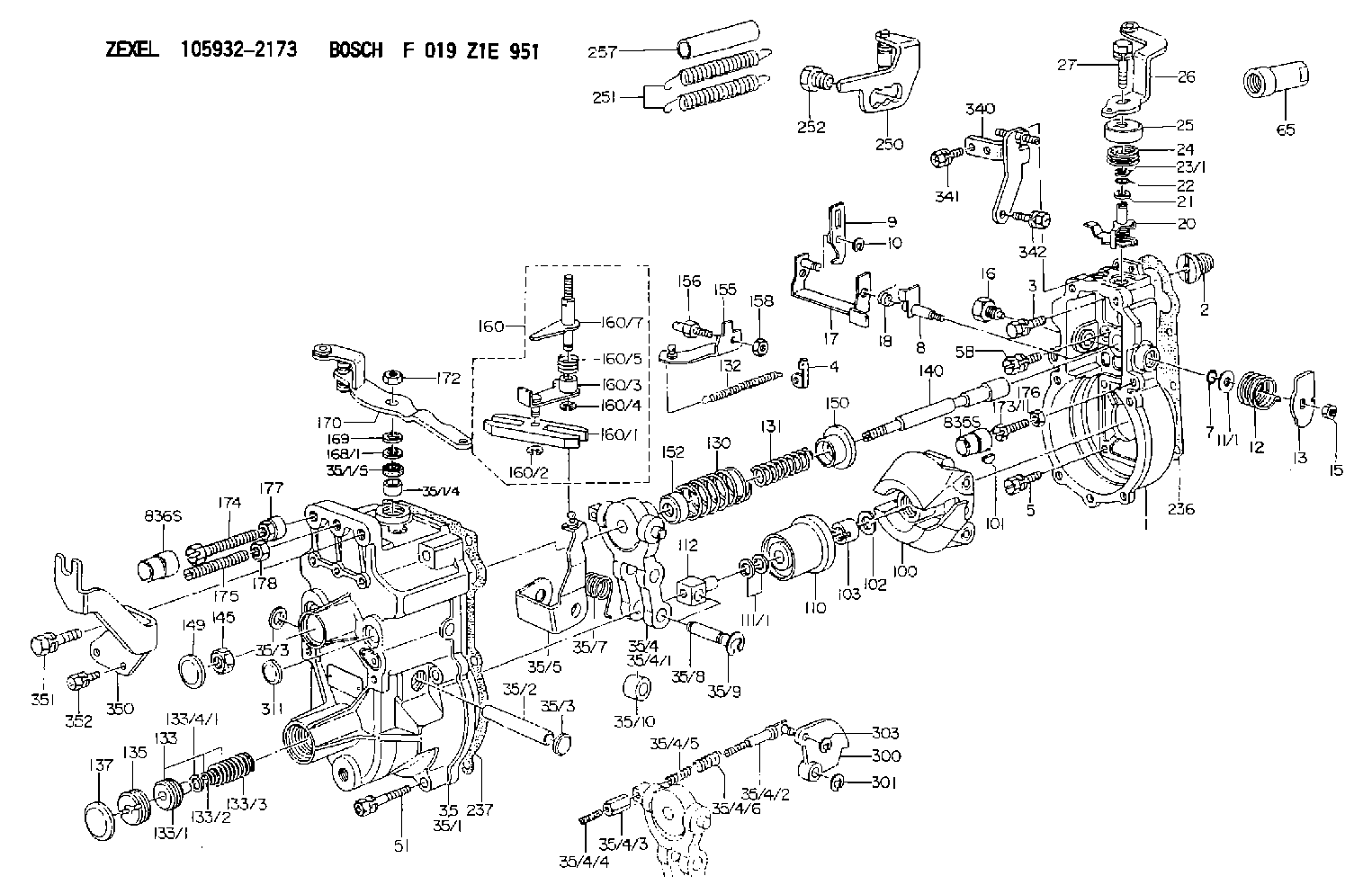
F 019 Z1E 951
f019z1e951
ZEXEL
105932-2173
1059322173
HINO
223009193A
223009193a
Rating:
Scheme ###:
| 1. | [1] | 159200-8620 | GOVERNOR HOUSING |
| 2. | [1] | 154007-0200 | ADAPTOR |
| 3. | [1] | 020018-1840 | BLEEDER SCREW M8P1.25L18 |
| 4. | [1] | 159232-2620 | PLATE |
| 5. | [5] | 029010-6810 | BLEEDER SCREW |
| 5B. | [1] | 020106-1640 | BLEEDER SCREW M6P1.0L14 |
| 7. | [1] | 016530-1010 | O-RING |
| 8. | [1] | 159205-2321 | LEVER SHAFT |
| 9. | [1] | 159202-5101 | CONTROL LEVER |
| 10. | [1] | 016010-0810 | LOCKING WASHER |
| 11/1. | [0] | 029311-0220 | SHIM D18&10.3T0.2 |
| 11/1. | [0] | 029311-0230 | SHIM D18&10.3T0.5 |
| 11/1. | [0] | 029311-0430 | SHIM D18&10.3T0.30 |
| 11/1. | [0] | 029311-0440 | SHIM D18&10.3T0.40 |
| 11/1. | [0] | 029311-0450 | SHIM D18&10.3T0.25 |
| 11/1. | [0] | 029311-0460 | SHIM D18&10.3T0.35 |
| 11/1. | [0] | 139410-3300 | SHIM D18&10.3T0.6 |
| 11/1. | [0] | 139410-3400 | SHIM D18&10.3T0.8 |
| 11/1. | [0] | 139410-3500 | SHIM D18&10.3T0.9 |
| 12. | [1] | 159215-0000 | COILED SPRING |
| 13. | [1] | 159242-6601 | CONTROL LEVER |
| 15. | [1] | 013020-8040 | UNION NUT M8P1.25H7 |
| 16. | [1] | 159237-5500 | CAPSULE |
| 17. | [1] | 159202-6820 | CONTROL LEVER |
| 18. | [1] | 159215-0300 | COILED SPRING |
| 20. | [1] | 159242-0220 | CONTROL LEVER |
| 21. | [1] | 159242-0600 | BUSHING |
| 22. | [1] | 029631-0030 | O-RING &9.8W2.3 |
| 23/1. | [0] | 029311-0220 | SHIM D18&10.3T0.2 |
| 23/1. | [0] | 029311-0230 | SHIM D18&10.3T0.5 |
| 23/1. | [0] | 029311-0430 | SHIM D18&10.3T0.30 |
| 23/1. | [0] | 029311-0440 | SHIM D18&10.3T0.40 |
| 23/1. | [0] | 029311-0450 | SHIM D18&10.3T0.25 |
| 23/1. | [0] | 029311-0460 | SHIM D18&10.3T0.35 |
| 23/1. | [0] | 139410-3300 | SHIM D18&10.3T0.6 |
| 23/1. | [0] | 139410-3400 | SHIM D18&10.3T0.8 |
| 23/1. | [0] | 139410-3500 | SHIM D18&10.3T0.9 |
| 24. | [1] | 159215-2000 | COILED SPRING |
| 25. | [1] | 159235-5800 | CAP |
| 26. | [1] | 159291-5220 | CONTROL LEVER |
| 27. | [1] | 020006-1640 | BLEEDER SCREW M6P1L16 4T |
| 35. | [1] | 159250-9820 | GOVERNOR COVER |
| 35/1. | [1] | 159201-3422 | GOVERNOR COVER |
| 35/1/4. | [1] | 159230-0902 | BUSHING |
| 35/1/5. | [1] | 029621-0080 | PACKING RING |
| 35/2. | [1] | 159205-0400 | LEVER SHAFT |
| 35/3. | [2] | 159237-0200 | CAPSULE |
| 35/3. | [2] | 159237-0200 | CAPSULE |
| 35/4. | [1] | 159253-4120 | TENSIONING LEVER |
| 35/4/1. | [1] | 159253-4020 | TENSIONING LEVER |
| 35/4/2. | [1] | 159204-5021 | RACK |
| 35/4/3. | [1] | 159233-0300 | UNION NUT |
| 35/4/4. | [1] | 159234-0300 | FLAT-HEAD SCREW |
| 35/4/5. | [1] | 159216-0000 | COILED SPRING |
| 35/4/6. | [1] | 159216-0100 | COILED SPRING |
| 35/5. | [1] | 159203-6120 | GUIDE LEVER |
| 35/7. | [1] | 159215-1701 | COILED SPRING |
| 35/8. | [1] | 159231-1300 | BEARING PIN |
| 35/9. | [2] | 016010-0610 | LOCKING WASHER |
| 35/10. | [1] | 159238-2900 | BUSHING |
| 51. | [7] | 020106-3840 | BLEEDER SCREW |
| 65. | [1] | 154050-1720 | STOPPING DEVICE |
| 100. | [1] | 154100-8920 | FLYWEIGHT ASSEMBLY |
| 101. | [1] | 025803-1610 | WOODRUFF KEY |
| 102. | [1] | 029321-2020 | LOCKING WASHER |
| 103. | [1] | 029231-2030 | UNION NUT |
| 110. | [1] | 154123-2320 | SLIDING PIECE |
| 111/1. | [0] | 029311-0010 | SHIM D14&10.1T0.2 |
| 111/1. | [0] | 029311-0180 | SHIM D14&10.1T0.3 |
| 111/1. | [0] | 029311-0190 | SHIM D14&10.1T0.40 |
| 111/1. | [0] | 029311-0210 | SHIM D14&10.1T1 |
| 111/1. | [0] | 139410-0000 | SHIM D14.0&10.1T0.5 |
| 111/1. | [0] | 139410-0100 | SHIM D14.0&10.1T1.5 |
| 111/1. | [0] | 139410-3000 | SHIM D14&10.1T2.0 |
| 111/1. | [0] | 139410-3100 | SHIM D14&10.1T3.0 |
| 111/1. | [0] | 139410-3200 | SHIM D14&10.1T4.0 |
| 112. | [1] | 159236-0200 | TERMINAL STUD |
| 130. | [1] | 159217-0500 | GOVERNOR SPRING |
| 131. | [1] | 159211-6200 | GOVERNOR SPRING |
| 132. | [1] | 159214-0000 | COILED SPRING |
| 133. | [1] | 159212-8220 | SPRING PACK |
| 133/1. | [1] | 159234-5602 | GUIDE SLEEVE |
| 133/2. | [1] | 159212-5000 | COILED SPRING |
| 133/3. | [1] | 159212-5700 | COILED SPRING |
| 133/4/1. | [0] | 029310-9240 | SHIM D11.9&9T0.1 |
| 133/4/1. | [0] | 029310-9250 | SHIM D11.9&9T0.2 |
| 133/4/1. | [0] | 029310-9260 | SHIM D11.9&9T0.25 |
| 133/4/1. | [0] | 029310-9270 | SHIM D11.9&9T1.0 |
| 133/4/1. | [0] | 139409-0100 | SHIM D11.9&9T0.3 |
| 133/4/1. | [0] | 139409-0200 | SHIM D11.9&9T0.5 |
| 133/4/1. | [0] | 139409-0300 | SHIM D11.5&9T0.8 |
| 135. | [1] | 159248-2700 | FLAT-HEAD SCREW |
| 137. | [1] | 159237-5300 | CAPSULE |
| 140. | [1] | 159205-2101 | LEVER SHAFT |
| 145. | [1] | 159233-5700 | UNION NUT |
| 149. | [1] | 159237-5400 | CAPSULE |
| 150. | [1] | 159235-5300 | SLOTTED WASHER |
| 152. | [1] | 159235-7200 | SLOTTED WASHER |
| 155. | [1] | 159204-7720 | STRAP |
| 156. | [1] | 159233-0520 | BLEEDER SCREW |
| 158. | [1] | 013020-5240 | UNION NUT M5P0.8H4 |
| 160. | [1] | 159252-0821 | LEVER GROUP |
| 160/1. | [1] | 159202-2200 | CONTROL LEVER |
| 160/2. | [1] | 016010-0810 | LOCKING WASHER |
| 160/3. | [1] | 159202-2120 | CONTROL LEVER |
| 160/4. | [1] | 016010-0810 | LOCKING WASHER |
| 160/5. | [1] | 159215-2301 | COILED SPRING |
| 160/7. | [1] | 159205-2222 | LEVER SHAFT |
| 168/1. | [0] | 029311-0640 | SHIM D26.0&10.2T0.95 |
| 168/1. | [0] | 029311-0650 | SHIM D26.0&10.2T0.20 |
| 168/1. | [0] | 029311-0660 | SHIM D26.0&10.2T0.25 |
| 168/1. | [0] | 029311-0670 | SHIM D26.0&10.2T0.30 |
| 168/1. | [0] | 029311-0680 | SHIM D26.0&10.2T0.35 |
| 168/1. | [0] | 029311-0690 | SHIM D26.0&10.2T0.40 |
| 168/1. | [0] | 029311-0700 | SHIM D26.0&10.2T0.50 |
| 168/1. | [0] | 139410-1400 | SHIM D26&10.2T0.7 |
| 168/1. | [0] | 139410-1500 | SHIM D26&10.2T0.9 |
| 168/1. | [0] | 139410-1600 | SHIM D26&10.2T0.8 |
| 168/1. | [0] | 139410-2700 | SHIM D26&10.2T0.6 |
| 169. | [1] | 139410-2300 | SHIM |
| 170. | [1] | 159267-9221 | CONTROL LEVER |
| 172. | [1] | 013020-8040 | UNION NUT M8P1.25H7 |
| 173/1. | [1] | 139006-7700 | BLEEDER SCREW |
| 173/1. | [1] | 139006-7800 | BLEEDER SCREW |
| 173/1. | [1] | 139006-7900 | BLEEDER SCREW |
| 173/1. | [1] | 139006-8000 | BLEEDER SCREW |
| 173/1. | [1] | 139006-8100 | BLEEDER SCREW |
| 173/1. | [1] | 139006-8200 | BLEEDER SCREW |
| 173/1. | [1] | 139006-8300 | BLEEDER SCREW |
| 174. | [1] | 154012-5500 | BLEEDER SCREW |
| 175. | [1] | 154013-3600 | FLAT-HEAD SCREW |
| 176. | [1] | 159233-7500 | UNION NUT |
| 177. | [1] | 154011-2300 | UNION NUT |
| 178. | [1] | 013020-8040 | UNION NUT M8P1.25H7 |
| 236. | [1] | 154390-1300 | GASKET |
| 237. | [1] | 159238-3100 | GASKET |
| 250. | [1] | 159222-9420 | BRACKET |
| 251. | [2] | 154338-2800 | COILED SPRING |
| 252. | [1] | 159248-0200 | BLEEDER SCREW |
| 257. | [2] | 154156-0500 | TUBE |
| 300. | [1] | 159288-7900 | CAM PLATE |
| 301. | [1] | 016010-0840 | LOCKING WASHER |
| 303. | [1] | 016010-0540 | LOCKING WASHER |
| 311. | [1] | 159237-0200 | CAPSULE |
| 340. | [1] | 159223-3120 | BRACKET |
| 341. | [2] | 020104-1040 | BLEEDER SCREW |
| 342. | [1] | 020046-1240 | BLEEDER SCREW M6P1L12 4T |
| 350. | [1] | 159222-7100 | BRACKET |
| 351. | [1] | 020118-1640 | BLEEDER SCREW |
| 352. | [2] | 020106-1240 | BLEEDER SCREW M6P1.0L12 |
| 835S. | [1] | 154062-1900 | CAP D12L24 |
| 836S. | [1] | 154062-1700 | CAP D20L32 |
Cross reference number
Zexel num
Bosch num
Firm num
Name
105932-2173
223009193A HINO
GOVERNOR
K 14JK MECHANICAL GOVERNOR GOV RLD GOV
K 14JK MECHANICAL GOVERNOR GOV RLD GOV
Information:
3-Cylinder Diesel Theory and Operation
The KDW 1003 diesel engine has an indirect injection (IDI) fuel delivery system. The fuel injectors are a unit style injector located in the cylinder head and actuated by the camshaft.As the camshaft turns, the adjustable pushrod forces the high-pressure plunger into the injector. The unit injector is then pressurized to 14,000 to 15000 kPa (2030 to 2175 psi) before injection. This process is known as popping pressure. The injection even will take place between 11° and 13° (BTDC) before the piston reaches top dead center.Refer to the engine emissions tag on the engine or the service manual for proper injection timing specifications. Refer to the service manual for the injection timing tool and procedures.The unit injectors are supplied low-pressure fuel from the electric fuel pump in the fuel tank to the injection lines coming through a grommet in the cylinder head. This pressure is between 60 to 70 kPa (8.7 to 10 psi). Fuel supply is hose A and fuel return is hose BCommon Specifications
Compression ratio: 22.8 to 1
Compression: new engine cold 2760 to 3100 kPa (400 to 450 psi) or old engine at 2415 to 2760 kPa (350 to 400 psi)
Compression minimum: 1725 kPa (250 psi) (below this pressure, cylinder misfire will occur)
Compression readingtaken through the glow plug hole, 563-4356 Test Kit
Firing order: 1 - 3 - 2
Supply fuel pressure: 60 to 70 kPa (8.7 to 10 psi)
Popping pressure: 14,000 to 15000 kPa (2030 to 2175 psi)
Thermostat open temperature: 78 to 82 °C (172.4 to 179.6 °F)
Thermostat fully open: 95 °C (203 °F)
Coolant fan on at 100.5 °C (213 °F) and off at 95 °C (203 °F)
Engine oil capacity: approximately 2.8 L (3 qt)
Engine oil (recommended): 5W-50 Synthetic
Engine oil pressure switch minimum opening pressure 30 kPa (4.35 psi) (on valve cover) normally close switch
Engine oil pressure at 120 °C (248 °F): 108 kPa (15.6 psi) at idle speed (800 to 900 rpm)Glow Plug and Thermistor
The KDW 1003 engine uses glow plug temperature sensor, or a thermistor, to adjust glow plug on time. The glow plugs are in the cylinder head precombustion chamber and heat up to 816 °C (1500 °F) to assist with starting the engine. The sensor is in the thermostat housing. As the coolant temperature rises, the sensor resistance goes down.The glow plug controller/relay is a plug-in device above the battery. The glow plug controller/relay applies 12 volts DC to the glow plugs in the precombustion chambers to aid in cold starting. Heating time is determined by the ECT thermistor signal and will vary from 0 seconds (warm engine) to approximately 30 seconds (cold engine).
Illustration 1 g06469140
(1) Black wire
(2) Brown wire
(3) Red/Orange wire
(4) Violet/White wire
(5) Orange wire
(6) Pink wire
(7) White/Blue wireUse the following procedure to test the glow plug relay. You will need a multimeter for the procedure.Note: The test should take 15 to 35 minutes.
Using an appropriate multimeter, select DC volts and connect the black test lead to the black wire (1) and the red test lead to the red/orange