Information governor
BOSCH
9 420 614 849
9420614849
ZEXEL
105932-1862
1059321862
Rating:
Scheme ###:
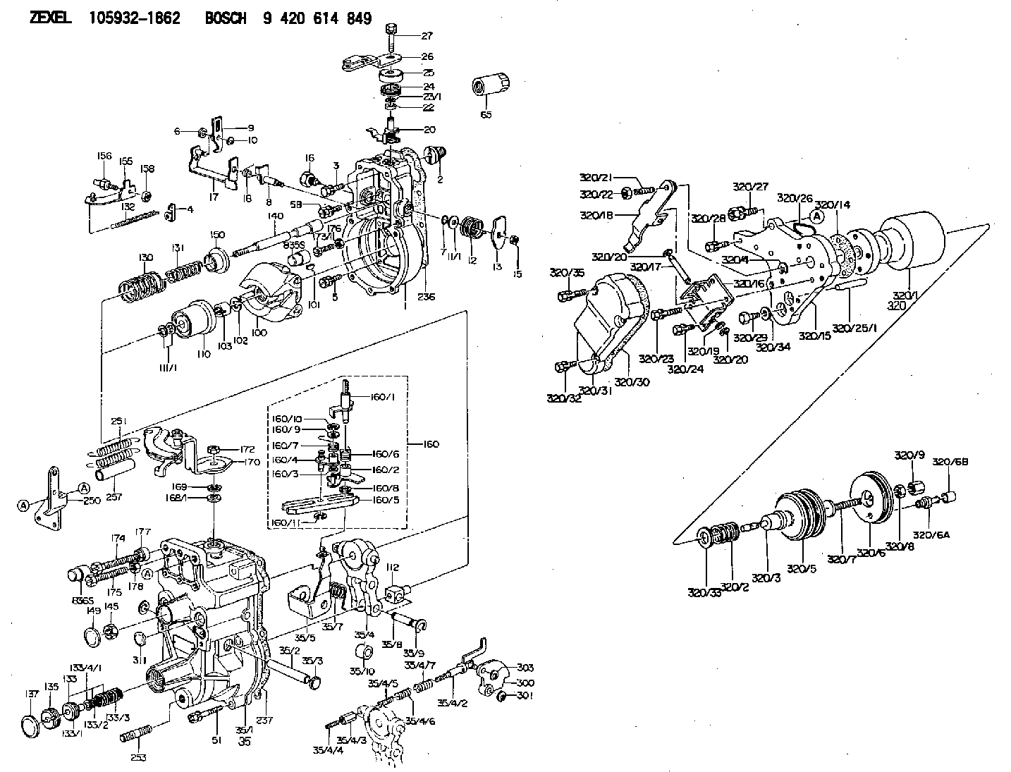
| 1. | [1] | 159200-7120 | GOVERNOR HOUSING |
| 2. | [1] | 154007-0200 | ADAPTOR |
| 3. | [1] | 020018-1840 | BLEEDER SCREW M8P1.25L18 |
| 4. | [1] | 159232-1600 | PLATE |
| 5. | [5] | 029010-6810 | BLEEDER SCREW |
| 5B. | [1] | 020106-1640 | BLEEDER SCREW M6P1.0L14 |
| 6. | [1] | 159242-0600 | BUSHING |
| 7. | [1] | 139710-0200 | O-RING |
| 8. | [1] | 159205-2321 | LEVER SHAFT |
| 9. | [1] | 159202-7800 | CONTROL LEVER |
| 10. | [1] | 016010-0810 | LOCKING WASHER |
| 11/1. | [0] | 029311-0220 | SHIM D18&10.3T0.2 |
| 11/1. | [0] | 029311-0230 | SHIM D18&10.3T0.5 |
| 11/1. | [0] | 029311-0430 | SHIM D18&10.3T0.30 |
| 11/1. | [0] | 029311-0440 | SHIM D18&10.3T0.40 |
| 11/1. | [0] | 029311-0450 | SHIM D18&10.3T0.25 |
| 11/1. | [0] | 029311-0460 | SHIM D18&10.3T0.35 |
| 11/1. | [0] | 139410-3300 | SHIM D18&10.3T0.6 |
| 11/1. | [0] | 139410-3400 | SHIM D18&10.3T0.8 |
| 11/1. | [0] | 139410-3500 | SHIM D18&10.3T0.9 |
| 12. | [1] | 159215-0000 | COILED SPRING |
| 13. | [1] | 159242-6601 | CONTROL LEVER |
| 15. | [1] | 013020-8040 | UNION NUT M8P1.25H7 |
| 16. | [1] | 159237-5500 | CAPSULE |
| 17. | [1] | 159202-5220 | CONTROL LEVER |
| 18. | [1] | 159215-0300 | COILED SPRING |
| 20. | [1] | 159291-0620 | CONTROL LEVER |
| 22. | [1] | 139610-0700 | PACKING RING |
| 23/1. | [0] | 139410-3800 | SHIM D22&10.2T0.2 |
| 23/1. | [0] | 139410-3900 | SHIM D22&10.2T0.3 |
| 23/1. | [0] | 139410-4000 | SHIM D22&10.2T0.4 |
| 23/1. | [0] | 139410-4100 | SHIM D22&10.2T0.6 |
| 23/1. | [0] | 139410-4200 | SHIM D22&10.2T0.8 |
| 24. | [1] | 159215-4200 | COILED SPRING |
| 25. | [1] | 159235-5800 | CAP |
| 26. | [1] | 159290-3021 | CONTROL LEVER |
| 27. | [1] | 020006-1240 | BLEEDER SCREW M6P1L12 4T |
| 35. | [1] | 159255-2120 | GOVERNOR COVER |
| 35/1. | [1] | 159301-6520 | GOVERNOR COVER |
| 35/2. | [1] | 159205-0400 | LEVER SHAFT |
| 35/3. | [2] | 159237-0200 | CAPSULE |
| 35/4. | [1] | 159253-2720 | TENSIONING LEVER |
| 35/4/2. | [1] | 159204-6022 | RACK |
| 35/4/3. | [1] | 159233-0300 | UNION NUT |
| 35/4/4. | [1] | 159234-0300 | FLAT-HEAD SCREW |
| 35/4/5. | [1] | 159216-0000 | COILED SPRING |
| 35/4/6. | [1] | 159216-0100 | COILED SPRING |
| 35/4/7. | [1] | 159216-0700 | COILED SPRING |
| 35/5. | [1] | 159203-6120 | GUIDE LEVER |
| 35/7. | [1] | 159215-1701 | COILED SPRING |
| 35/8. | [1] | 159231-1300 | BEARING PIN |
| 35/9. | [2] | 016010-0610 | LOCKING WASHER |
| 35/10. | [1] | 159238-2900 | BUSHING |
| 51. | [7] | 020106-3840 | BLEEDER SCREW |
| 65. | [1] | 155404-5700 | CAP |
| 100. | [1] | 154101-0420 | FLYWEIGHT ASSEMBLY |
| 101. | [1] | 025803-1610 | WOODRUFF KEY |
| 102. | [1] | 029321-2020 | LOCKING WASHER |
| 103. | [1] | 029231-2030 | UNION NUT |
| 110. | [1] | 154123-2320 | SLIDING PIECE |
| 111/1. | [0] | 029311-0010 | SHIM D14&10.1T0.2 |
| 111/1. | [0] | 029311-0180 | SHIM D14&10.1T0.3 |
| 111/1. | [0] | 029311-0190 | SHIM D14&10.1T0.40 |
| 111/1. | [0] | 029311-0210 | SHIM D14&10.1T1 |
| 111/1. | [0] | 139410-0000 | SHIM D14.0&10.1T0.5 |
| 111/1. | [0] | 139410-0100 | SHIM D14.0&10.1T1.5 |
| 111/1. | [0] | 139410-3000 | SHIM D14&10.1T2.0 |
| 111/1. | [0] | 139410-3100 | SHIM D14&10.1T3.0 |
| 111/1. | [0] | 139410-3200 | SHIM D14&10.1T4.0 |
| 112. | [1] | 159236-0200 | TERMINAL STUD |
| 130. | [1] | 159210-1800 | GOVERNOR SPRING |
| 131. | [1] | 159211-3700 | GOVERNOR SPRING |
| 132. | [1] | 159214-0200 | COILED SPRING |
| 133. | [1] | 159212-8220 | SPRING PACK |
| 133/1. | [1] | 159234-5602 | GUIDE SLEEVE |
| 133/2. | [1] | 159212-5000 | COILED SPRING |
| 133/3. | [1] | 159212-5700 | COILED SPRING |
| 133/4/1. | [0] | 029310-9240 | SHIM D11.9&9T0.1 |
| 133/4/1. | [0] | 029310-9250 | SHIM D11.9&9T0.2 |
| 133/4/1. | [0] | 029310-9260 | SHIM D11.9&9T0.25 |
| 133/4/1. | [0] | 029310-9270 | SHIM D11.9&9T1.0 |
| 133/4/1. | [0] | 139409-0100 | SHIM D11.9&9T0.3 |
| 133/4/1. | [0] | 139409-0200 | SHIM D11.9&9T0.5 |
| 133/4/1. | [0] | 139409-0300 | SHIM D11.5&9T0.8 |
| 135. | [1] | 159248-2700 | FLAT-HEAD SCREW |
| 137. | [1] | 159237-5300 | CAPSULE |
| 140. | [1] | 159205-2101 | LEVER SHAFT |
| 145. | [1] | 159233-5700 | UNION NUT |
| 149. | [1] | 159237-5400 | CAPSULE |
| 150. | [1] | 159235-5300 | SLOTTED WASHER |
| 155. | [1] | 159204-7420 | STRAP |
| 156. | [1] | 159233-0620 | BLEEDER SCREW |
| 158. | [1] | 013020-5240 | UNION NUT M5P0.8H4 |
| 160. | [1] | 159252-2221 | LEVER GROUP |
| 160/1. | [1] | 159205-3711 | LEVER SHAFT |
| 160/2. | [1] | 159202-4810 | CONTROL LEVER |
| 160/3. | [1] | 029310-6030 | SHIM D11.5&6.2T0.2 |
| 160/4. | [1] | 159202-4520 | CONTROL LEVER |
| 160/5. | [1] | 159202-2200 | CONTROL LEVER |
| 160/6. | [1] | 159215-2301 | COILED SPRING |
| 160/7. | [1] | 159215-3900 | COILED SPRING |
| 160/8. | [1] | 016010-0810 | LOCKING WASHER |
| 160/9. | [1] | 014020-6140 | PLAIN WASHER |
| 160/10. | [1] | 016010-0610 | LOCKING WASHER |
| 160/11. | [1] | 016010-0810 | LOCKING WASHER |
| 168/1. | [0] | 029311-0640 | SHIM D26.0&10.2T0.95 |
| 168/1. | [0] | 029311-0650 | SHIM D26.0&10.2T0.20 |
| 168/1. | [0] | 029311-0660 | SHIM D26.0&10.2T0.25 |
| 168/1. | [0] | 029311-0670 | SHIM D26.0&10.2T0.30 |
| 168/1. | [0] | 029311-0680 | SHIM D26.0&10.2T0.35 |
| 168/1. | [0] | 029311-0690 | SHIM D26.0&10.2T0.40 |
| 168/1. | [0] | 029311-0700 | SHIM D26.0&10.2T0.50 |
| 168/1. | [0] | 139410-1400 | SHIM D26&10.2T0.7 |
| 168/1. | [0] | 139410-1500 | SHIM D26&10.2T0.9 |
| 168/1. | [0] | 139410-1600 | SHIM D26&10.2T0.8 |
| 168/1. | [0] | 139410-2700 | SHIM D26&10.2T0.6 |
| 169. | [1] | 159238-4300 | SHIM |
| 170. | [1] | 159263-4421 | CONTROL LEVER |
| 172. | [1] | 013020-8040 | UNION NUT M8P1.25H7 |
| 173/1. | [1] | 139006-3500 | BLEEDER SCREW M6P1.0L33 |
| 173/1. | [1] | 139006-3700 | BLEEDER SCREW M6P1.0L34 |
| 173/1. | [1] | 139006-3800 | BLEEDER SCREW M6P1.0L35 |
| 173/1. | [1] | 139006-3900 | BLEEDER SCREW M6P1.0L36 |
| 173/1. | [1] | 139006-5300 | BLEEDER SCREW M6P1.0L31 |
| 173/1. | [1] | 139006-5400 | BLEEDER SCREW M6P1.0L32 |
| 173/1. | [1] | 155615-2500 | BLEEDER SCREW M6P1.0L37 |
| 174. | [1] | 154010-7200 | BLEEDER SCREW M8P1.25L62 |
| 174B. | [1] | 154010-8100 | BLEEDER SCREW M8P1.25L65 |
| 175. | [1] | 154010-8100 | BLEEDER SCREW M8P1.25L65 |
| 176. | [1] | 159225-8600 | UNION NUT |
| 177. | [1] | 154011-2300 | UNION NUT |
| 178. | [1] | 154011-2800 | UNION NUT |
| 236. | [1] | 154390-0000 | GASKET |
| 237. | [1] | 159238-3100 | GASKET |
| 250. | [1] | 159221-2920 | BRACKET |
| 251. | [2] | 154317-8800 | COILED SPRING |
| 253. | [1] | 139010-0000 | STUD |
| 257. | [2] | 154156-0900 | TUBE |
| 300. | [1] | 159287-4800 | CAM PLATE |
| 301. | [1] | 016010-0840 | LOCKING WASHER |
| 303. | [1] | 016010-0540 | LOCKING WASHER |
| 311. | [1] | 159237-0200 | CAPSULE |
| 320. | [1] | 155424-7120 | ANEROID CAPSULE |
| 320/1. | [1] | 155424-6520 | DIAPHRAGM HOUSING |
| 320/2. | [1] | 155423-8200 | COILED SPRING |
| 320/3. | [1] | 155423-0300 | STOP PIN |
| 320/4. | [1] | 016020-1220 | LOCKING WASHER |
| 320/5. | [1] | 155403-3021 | BELLOWS |
| 320/6. | [1] | 155423-2000 | COVER |
| 320/6A. | [1] | 139805-0000 | JOINT CONNECTION |
| 320/6B. | [1] | 155424-0300 | CAP |
| 320/7. | [1] | 155423-1500 | SCREW PLUG |
| 320/8. | [1] | 029240-6010 | UNION NUT M6P1.0H5* |
| 320/9. | [1] | 154035-1600 | CAP NUT |
| 320/14. | [1] | 154390-2700 | GASKET |
| 320/15. | [1] | 155423-0700 | SPACER BUSHING |
| 320/16. | [1] | 155423-0800 | PLATE |
| 320/17. | [1] | 155423-0900 | LEVER SHAFT |
| 320/18. | [1] | 155423-1000 | CONTROL LEVER |
| 320/19. | [2] | 029310-4060 | SHIM |
| 320/20. | [2] | 016010-0440 | LOCKING WASHER |
| 320/20. | [2] | 016010-0440 | LOCKING WASHER |
| 320/21. | [1] | 155423-1100 | FLAT-HEAD SCREW |
| 320/22. | [1] | 013020-6010 | UNION NUT |
| 320/23. | [2] | 020105-2540 | BLEEDER SCREW |
| 320/23B. | [2] | 020105-2040 | BLEEDER SCREW M5P0.8L20 |
| 320/24. | [2] | 020105-0840 | BLEEDER SCREW M5P0.5L8 |
| 320/25/1. | [1] | 155423-1200 | STOP PIN L102 |
| 320/25/1. | [1] | 155424-4900 | STOP PIN L95 |
| 320/25/1. | [1] | 155424-5000 | STOP PIN L96 |
| 320/25/1B. | [1] | 155423-1300 | STOP PIN L102.5 |
| 320/25/1C. | [1] | 155423-1400 | STOP PIN L103 |
| 320/25/1D. | [1] | 155423-7600 | STOP PIN L103.5 |
| 320/25/1E. | [1] | 155423-7700 | STOP PIN L104 |
| 320/25/1F. | [1] | 155423-8700 | STOP PIN L97 |
| 320/25/1G. | [1] | 155423-8800 | STOP PIN L98 |
| 320/25/1H. | [1] | 155423-8900 | STOP PIN L99 |
| 320/25/1I. | [1] | 155423-9000 | STOP PIN L100 |
| 320/25/1J. | [1] | 155423-9100 | STOP PIN L101 |
| 320/26. | [1] | 159226-4500 | SPACER RING |
| 320/27. | [1] | 020118-2540 | BLEEDER SCREW |
| 320/28. | [2] | 020106-2240 | BLEEDER SCREW |
| 320/28B. | [1] | 020106-1840 | BLEEDER SCREW M6P1L18 |
| 320/29. | [1] | 139006-1800 | BLEEDER SCREW |
| 320/30. | [1] | 154390-2800 | GASKET |
| 320/31. | [1] | 155423-0500 | COVER |
| 320/32. | [2] | 020105-1240 | BLEEDER SCREW M5P0.8L12 |
| 320/33. | [1] | 029311-2060 | SHIM D22&12.5T0.5 |
| 320/34. | [1] | 026506-1040 | GASKET D9.9&6.2T1 |
| 320/35. | [2] | 020105-2540 | BLEEDER SCREW |
| 835S. | [1] | 154062-1900 | CAP D12L24 |
| 836S. | [1] | 154062-1700 | CAP D20L32 |
Include in #1:
101401-7332
as GOVERNOR
Cross reference number
Zexel num
Bosch num
Firm num
Name
Information:
Procedure
Illustration 1 g06220548
(1) TC Mark (Flywheel Housing)
(2) TC Mark (Flywheel)
Remove valve cover, and injector and rocker arm. Bring the piston of cylinder 4 to TDC.
Illustration 2 g06220554
(3) Dial Gauge
(4) Valve
(5) O-ring
Remove the #4 exhaust valve bridge arm and valve spring. Insert a small O-ring (5) so the valve does not fall into the cylinder.
Set dial gauge (3) on the tip of the valve (4).
Illustration 3 g06220569
(6) Tri - Square
(7) Flywheel Housing
(8) Flywheel
Illustration 4 g06220573
(7) Flywheel Housing
(8) Flywheel
(9) Reference Line
Turn the flywheel counterclockwise and measure the position where the tip of the valve is the highest.
Stop the flywheel at the position where the tip of the valve is the highest. Put a tri - square (6) on the flywheel housing (7) and the flywheel (8) and draw a reference line (9).Do not drop the valve (4) into the cylinder. When measuring the highest position of the tip of the valve, do not rotate the flywheel clockwise. If you go past the highest point of the valve, back up the flywheel slightly and measure the highest point of the valve. The reference line (9) indicates the TDC of the crankshaft.
Illustration 5 g06220579
Rotation Sensor Signal Interface Unit
Application: Use for reading rotation sensor signal.
(1) 9V Battery
(2) Switch
(3) 3-Terminal Regulator
(4) LED
(5) Clip (Red)
(6) Clip (Black)
(A) for Panasonic
(B) for Denso
(C) for Bosch cam angle
(D) for Bosch crank angle
((E)) Connector Side
(a) +9 V
(b) Signal
(c) GND
(d) +5 V
(e) Signal
(f) GND
Schematic to build Rotation Sensor Signal Interface.
Illustration 6 g06220581
(10) Rotation Sensor Signal Interface (Tool not available. Schematic to build tool available. Refer to Step 6.
(11) Tester
Illustration 7 g06220587
(12) Ground Terminal
(13) Output Terminal
(14) Crankshaft Position Sensor
Connect a connector of the rotation sensor signal interface unit (10) to the crankshaft position sensor (14). Connect each clip of the rotation sensor signal interface unit (10) to the same test lead color of the tester (11). Switch on the rotation sensor signal interface unit (10).
Illustration 8 g06220590
(15) Pulsar Gear
(16) 14th Tooth
(17) Missing Teeth
Turn the flywheel and make sure that the voltage of the crankshaft position sensor goes from 0→ 5 V or 5 → 0 V.
Rotate the flywheel and align the crankshaft position sensor to the part of the pulsar gear (15) that is missing teeth (17). The 14th tooth (16) from the missing teeth is standard.
Slowly turn flywheel counterclockwise and stop flywheel at the point where needle of the tester changes momentarily from 0 → 5 V, the 14th tooth.That point is where the crankshaft position sensor detects TDC.
Illustration 9 g06220608
(18) Crankshaft TDC
(19) Detection Point of Crankshaft Position Sensor TDC
Illustration 10 g06220612
(20) Interval
Set the tri - square (6) on the reference line (9) on the flywheel housing side and mark the detection point of crankshaft position sensor TDC (19) on the flywheel.
Measure the interval (20) between the crankshaft TDC (18) and the detection point of the crankshaft position sensor TDC (19).
Calculation of fuel injection timing correction 1.0 mm (0.039 in.): 0.321°.Corrected Angle = 0.321° X actual interval
Overwrite the injection timing correction value on the engine ecm registration website refer to REHS9707, "Registering Diesel Particulate Filter (DPF), Diesel Oxidation Catalyst (DOC),