Information governor
BOSCH
9 420 611 911
9420611911
ZEXEL
105932-1252
1059321252

Rating:
Scheme ###:
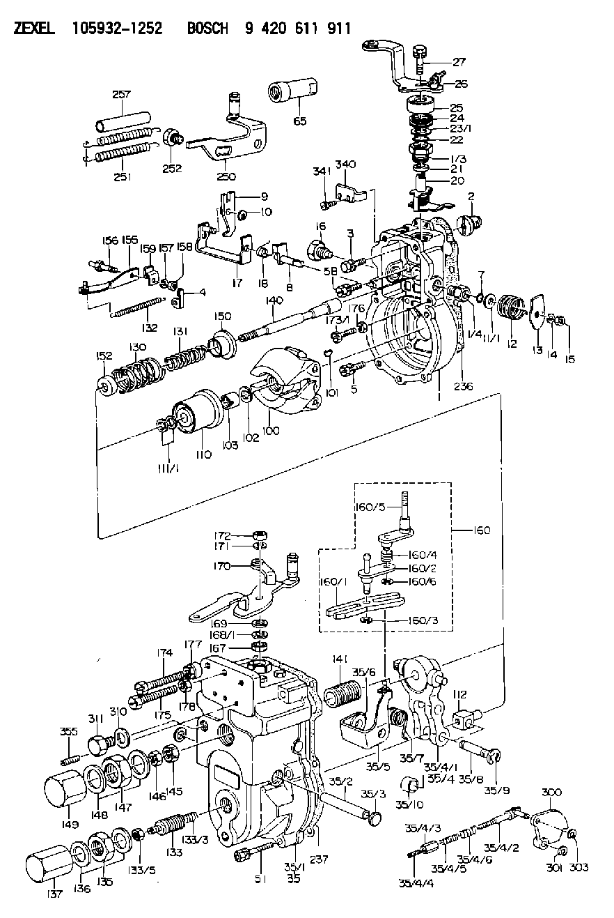
| 1. | [1] | 159200-7820 | GOVERNOR HOUSING |
| 1/3. | [1] | 154321-0400 | BUSHING |
| 1/4. | [1] | 154321-0400 | BUSHING |
| 2. | [1] | 154007-0200 | ADAPTOR |
| 3. | [1] | 020018-1840 | BLEEDER SCREW M8P1.25L18 |
| 4. | [1] | 159232-0801 | PLATE |
| 5. | [5] | 029010-6810 | BLEEDER SCREW |
| 5B. | [1] | 020106-1640 | BLEEDER SCREW M6P1.0L14 |
| 7. | [1] | 029631-0030 | O-RING &9.8W2.3 |
| 8. | [1] | 159205-2321 | LEVER SHAFT |
| 9. | [1] | 159202-2301 | CONTROL LEVER |
| 10. | [1] | 016010-0810 | LOCKING WASHER |
| 11/1. | [0] | 029311-0520 | SHIM D20.8&10.3T0.2 |
| 11/1. | [0] | 029311-0530 | SHIM D20.8&10.3T0.25 |
| 11/1. | [0] | 029311-0540 | SHIM D20.8&10.3T0.3 |
| 11/1. | [0] | 029311-0550 | SHIM D20.8&10.3T0.35 |
| 11/1. | [0] | 029311-0560 | SHIM D20.8&10.3T0.4 |
| 11/1. | [0] | 029311-0570 | SHIM D20.8&10.3T0.5 |
| 12. | [1] | 159215-0000 | COILED SPRING |
| 13. | [1] | 159242-0100 | CONTROL LEVER |
| 14. | [1] | 014110-8440 | LOCKING WASHER |
| 15. | [1] | 013020-8040 | UNION NUT M8P1.25H7 |
| 16. | [1] | 159237-0000 | CAPSULE |
| 17. | [1] | 159202-2420 | CONTROL LEVER |
| 18. | [1] | 159215-0300 | COILED SPRING |
| 20. | [1] | 159242-7820 | CONTROL LEVER |
| 21. | [1] | 159242-0600 | BUSHING |
| 22. | [1] | 029631-0030 | O-RING &9.8W2.3 |
| 23/1. | [0] | 029311-0520 | SHIM D20.8&10.3T0.2 |
| 23/1. | [0] | 029311-0530 | SHIM D20.8&10.3T0.25 |
| 23/1. | [0] | 029311-0540 | SHIM D20.8&10.3T0.3 |
| 23/1. | [0] | 029311-0550 | SHIM D20.8&10.3T0.35 |
| 23/1. | [0] | 029311-0560 | SHIM D20.8&10.3T0.4 |
| 23/1. | [0] | 029311-0570 | SHIM D20.8&10.3T0.5 |
| 24. | [1] | 159215-2900 | COILED SPRING |
| 25. | [1] | 154322-0100 | CAP |
| 26. | [1] | 159291-1020 | CONTROL LEVER |
| 27. | [1] | 020006-1640 | BLEEDER SCREW M6P1L16 4T |
| 35. | [1] | 159255-1720 | GOVERNOR COVER |
| 35/1. | [1] | 159201-2410 | GOVERNOR COVER |
| 35/2. | [1] | 159205-0400 | LEVER SHAFT |
| 35/3. | [2] | 159237-0200 | CAPSULE |
| 35/4. | [1] | 159253-4320 | TENSIONING LEVER |
| 35/4/1. | [1] | 159253-4220 | TENSIONING LEVER |
| 35/4/2. | [1] | 159204-5021 | RACK |
| 35/4/3. | [1] | 159233-0300 | UNION NUT |
| 35/4/4. | [1] | 159234-0000 | FLAT-HEAD SCREW |
| 35/4/5. | [1] | 159216-0000 | COILED SPRING |
| 35/4/6. | [1] | 159216-0100 | COILED SPRING |
| 35/5. | [1] | 159203-5320 | GUIDE LEVER |
| 35/6. | [2] | 159235-5000 | BUSHING |
| 35/7. | [1] | 159215-5600 | COILED SPRING |
| 35/8. | [1] | 159231-1300 | BEARING PIN |
| 35/9. | [2] | 016010-0610 | LOCKING WASHER |
| 35/10. | [1] | 159238-1801 | BUSHING |
| 51. | [7] | 020106-3840 | BLEEDER SCREW |
| 65. | [1] | 154050-1720 | STOPPING DEVICE |
| 100. | [1] | 154100-8920 | FLYWEIGHT ASSEMBLY |
| 101. | [1] | 025803-1610 | WOODRUFF KEY |
| 102. | [1] | 029321-2020 | LOCKING WASHER |
| 103. | [1] | 029231-2030 | UNION NUT |
| 110. | [1] | 154123-2320 | SLIDING PIECE |
| 111/1. | [0] | 029311-0010 | SHIM D14&10.1T0.2 |
| 111/1. | [0] | 029311-0180 | SHIM D14&10.1T0.3 |
| 111/1. | [0] | 029311-0190 | SHIM D14&10.1T0.40 |
| 111/1. | [0] | 029311-0210 | SHIM D14&10.1T1 |
| 111/1. | [0] | 139410-0000 | SHIM D14.0&10.1T0.5 |
| 111/1. | [0] | 139410-0100 | SHIM D14.0&10.1T1.5 |
| 111/1. | [0] | 139410-3000 | SHIM D14&10.1T2.0 |
| 111/1. | [0] | 139410-3100 | SHIM D14&10.1T3.0 |
| 111/1. | [0] | 139410-3200 | SHIM D14&10.1T4.0 |
| 112. | [1] | 159236-0100 | TERMINAL STUD |
| 130. | [1] | 159210-9300 | GOVERNOR SPRING |
| 131. | [1] | 159211-6100 | GOVERNOR SPRING |
| 132. | [1] | 159214-0000 | COILED SPRING |
| 133. | [1] | 159219-2320 | HEADLESS SCREW |
| 133/3. | [1] | 159219-2700 | COILED SPRING |
| 133/5. | [1] | 013020-6040 | UNION NUT M6P1H5 |
| 135. | [1] | 159248-0600 | UNION NUT |
| 136. | [2] | 026520-2440 | GASKET D23.9&20.2T1 |
| 137. | [1] | 159248-0700 | CAP |
| 140. | [1] | 159205-1801 | LEVER SHAFT |
| 141. | [1] | 159234-5200 | GUIDE SLEEVE |
| 145. | [1] | 159233-5000 | UNION NUT |
| 146. | [1] | 023020-8040 | UNION NUT M8P1H5 |
| 147. | [1] | 139222-0200 | UNION NUT |
| 148. | [2] | 026522-2740 | GASKET D26.9&22.2T1 |
| 149. | [1] | 159237-5000 | CAP |
| 150. | [1] | 159235-5300 | SLOTTED WASHER |
| 152. | [1] | 159235-6700 | SLOTTED WASHER |
| 155. | [1] | 159204-0320 | STRAP |
| 156. | [1] | 159237-0300 | BLEEDER SCREW |
| 157. | [1] | 014110-5440 | LOCKING WASHER |
| 158. | [1] | 159233-5620 | UNION NUT |
| 159. | [1] | 159242-0800 | PLATE |
| 160. | [1] | 159252-0521 | LEVER GROUP |
| 160/1. | [1] | 159202-1400 | CONTROL LEVER |
| 160/2. | [1] | 159202-1520 | CONTROL LEVER |
| 160/3. | [1] | 016010-0610 | LOCKING WASHER |
| 160/4. | [1] | 159215-1300 | COILED SPRING |
| 160/5. | [1] | 159205-1721 | LEVER SHAFT |
| 160/6. | [1] | 016010-0810 | LOCKING WASHER |
| 167. | [1] | 029621-0080 | PACKING RING |
| 168/1. | [0] | 029311-0640 | SHIM D26.0&10.2T0.95 |
| 168/1. | [0] | 029311-0650 | SHIM D26.0&10.2T0.20 |
| 168/1. | [0] | 029311-0660 | SHIM D26.0&10.2T0.25 |
| 168/1. | [0] | 029311-0670 | SHIM D26.0&10.2T0.30 |
| 168/1. | [0] | 029311-0680 | SHIM D26.0&10.2T0.35 |
| 168/1. | [0] | 029311-0690 | SHIM D26.0&10.2T0.40 |
| 168/1. | [0] | 029311-0700 | SHIM D26.0&10.2T0.50 |
| 168/1. | [0] | 139410-1400 | SHIM D26&10.2T0.7 |
| 168/1. | [0] | 139410-1500 | SHIM D26&10.2T0.9 |
| 168/1. | [0] | 139410-1600 | SHIM D26&10.2T0.8 |
| 168/1. | [0] | 139410-2700 | SHIM D26&10.2T0.6 |
| 169. | [1] | 139410-2300 | SHIM |
| 170. | [1] | 159267-9521 | CONTROL LEVER |
| 171. | [1] | 014110-8440 | LOCKING WASHER |
| 172. | [1] | 013020-8040 | UNION NUT M8P1.25H7 |
| 173/1. | [1] | 139006-3500 | BLEEDER SCREW M6P1.0L33 |
| 173/1. | [1] | 139006-3700 | BLEEDER SCREW M6P1.0L34 |
| 173/1. | [1] | 139006-3800 | BLEEDER SCREW M6P1.0L35 |
| 173/1. | [1] | 139006-3900 | BLEEDER SCREW M6P1.0L36 |
| 173/1. | [1] | 139006-5300 | BLEEDER SCREW M6P1.0L31 |
| 173/1. | [1] | 139006-5400 | BLEEDER SCREW M6P1.0L32 |
| 173/1. | [1] | 155615-2500 | BLEEDER SCREW M6P1.0L37 |
| 174. | [1] | 154010-8000 | BLEEDER SCREW |
| 175. | [1] | 154013-3600 | FLAT-HEAD SCREW |
| 176. | [1] | 159225-8600 | UNION NUT |
| 177. | [1] | 154011-2300 | UNION NUT |
| 178. | [1] | 154011-0100 | HEXAGON NUT |
| 236. | [1] | 154390-1300 | GASKET |
| 237. | [1] | 154390-1100 | GASKET |
| 250. | [1] | 159221-8920 | BRACKET |
| 251. | [2] | 154338-3200 | COILED SPRING |
| 252. | [1] | 159248-0200 | BLEEDER SCREW |
| 257. | [2] | 154156-0500 | TUBE |
| 300. | [1] | 159288-0300 | CAM PLATE |
| 301. | [1] | 016010-0840 | LOCKING WASHER |
| 303. | [1] | 016010-0540 | LOCKING WASHER |
| 310. | [1] | 026516-2040 | GASKET D19.9&16.2T1 |
| 311. | [1] | 159237-0100 | CAPSULE |
| 340. | [1] | 159221-9000 | PLATE |
| 341. | [2] | 020104-1040 | BLEEDER SCREW |
| 355. | [2] | 139006-7500 | STUD |
Include in #1:
101603-2231
as GOVERNOR
Cross reference number
Zexel num
Bosch num
Firm num
Name
Information:
Procedure
Note: Prior to performing the analysis with the APC, be sure to read and understand all the interferences listed in the "Interferences Inherent In the Fuel Sample" section of this document. Ensure that all precautions have been taken to minimize the affect of skewed results due to improper sampling, handling, or preparation.
Obtain the fuel sample to be analyzed in an appropriate sample bottle as described in the "Fuel Sample Preparation" section. Manually or mechanically shake the sample vigorously for 30 seconds. When manually shaking a sample, ensure thorough mixing of the sample by turning the bottle so that the lid is facing downward. Shake by moving the wrist and/or forearm up and down as rapidly as is comfortable for the 30 seconds.Note: Degassing samples can be accomplished with either the use of an ultrasonic bath or with the use of a vacuum pump.
Immediately degas the sample, by partially opening the lid to the bottle and placing the sample upright in the degassing unit. Perform only one of the degassing methods. An ultrasonic bath is the best method for degassing a sample. An ultrasonic bath takes the least amount of time minimizing the impact of particle settling.Note: The purpose of partially unscrewing or opening the lid is to promote quick degassing of the sample. Air bubbles to remaining near the surface of the sample following the degassing process are acceptable.
Illustration 5 g01741117
If an ultrasonic bath is unavailable, an alternative method of degassing the sample is with the use of a 1U-5718 Oil Sampling Vacuum Pump. Ensure the 1U-5718 Oil Sampling Vacuum Pump is clean before beginning the degas process.Note: Rubber is to be placed over the hole of the tubing for the pump to develop and hold the required vacuum.
With the sample to be analyzed in the sample bottle, thread the bottle into the bottom of the 1U-5718 Oil Sampling Vacuum Group. Operate the pump to create a vacuum. Maintain the vacuum until all air bubbles have risen to the surface of the sample and dissipated.
If an ultrasonic bath or a vacuum pump is not available, the sample can degas naturally. Degas the sample by setting the sample on a flat surface and leaving the sample undisturbed. If the APC performs a flushing cycle, let the sample sit for 15 seconds. If the APC does not perform a flushing cycle, such as the 293-8413 HYDAC Contamination Monitor Group or the 383-4255 HYDAC Contamination Monitor Group, let the sample sit for 30 seconds. Proceed to the "Sample Processing" section.Sample Processing
Remove the lid from the sample bottle. Immediately begin the processing of the sample on the APC that has been prepared according to the "Fuel Sample Preparation" section.Note: If more than 45 seconds elapse after the shaking of the sample, the procedure shall be restarted with shaking of the sample in "Fuel Sample Preparation" section. Shaking the sample ensures that suspended particles do not settle to the bottom of the sample, causing inaccurate particle count results.
Obtain the particle count results