Information governor
BOSCH
9 420 613 101
9420613101
ZEXEL
105932-0720
1059320720
ISUZU
8971218370
8971218370
Rating:
Scheme ###:
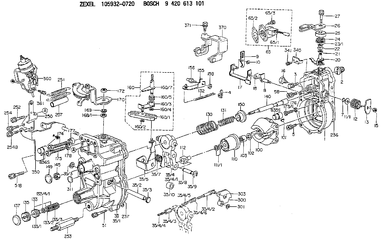
| 1. | [1] | 159200-7220 | GOVERNOR HOUSING |
| 2. | [1] | 154007-0200 | ADAPTOR |
| 3. | [1] | 020018-1840 | BLEEDER SCREW M8P1.25L18 |
| 4. | [1] | 159232-2300 | PLATE |
| 5. | [5] | 029010-6810 | BLEEDER SCREW |
| 5B. | [1] | 020106-1640 | BLEEDER SCREW M6P1.0L14 |
| 7. | [1] | 139710-0200 | O-RING |
| 8. | [1] | 159205-2321 | LEVER SHAFT |
| 9. | [1] | 159202-7200 | CONTROL LEVER |
| 10. | [1] | 016010-0810 | LOCKING WASHER |
| 11/1. | [0] | 029311-0220 | SHIM D18&10.3T0.2 |
| 11/1. | [0] | 029311-0230 | SHIM D18&10.3T0.5 |
| 11/1. | [0] | 029311-0430 | SHIM D18&10.3T0.30 |
| 11/1. | [0] | 029311-0440 | SHIM D18&10.3T0.40 |
| 11/1. | [0] | 029311-0450 | SHIM D18&10.3T0.25 |
| 11/1. | [0] | 029311-0460 | SHIM D18&10.3T0.35 |
| 11/1. | [0] | 139410-3300 | SHIM D18&10.3T0.6 |
| 11/1. | [0] | 139410-3400 | SHIM D18&10.3T0.8 |
| 11/1. | [0] | 139410-3500 | SHIM D18&10.3T0.9 |
| 12. | [1] | 159215-0000 | COILED SPRING |
| 13. | [1] | 159242-6601 | CONTROL LEVER |
| 15. | [1] | 013020-8040 | UNION NUT M8P1.25H7 |
| 16. | [1] | 159237-5500 | CAPSULE |
| 17. | [1] | 159202-5320 | CONTROL LEVER |
| 18. | [1] | 159215-0300 | COILED SPRING |
| 20. | [1] | 159242-0220 | CONTROL LEVER |
| 21. | [1] | 029311-0210 | SHIM D14&10.1T1 |
| 22. | [1] | 139610-0700 | PACKING RING |
| 23/1. | [0] | 139410-3800 | SHIM D22&10.2T0.2 |
| 23/1. | [0] | 139410-3900 | SHIM D22&10.2T0.3 |
| 23/1. | [0] | 139410-4000 | SHIM D22&10.2T0.4 |
| 23/1. | [0] | 139410-4100 | SHIM D22&10.2T0.6 |
| 23/1. | [0] | 139410-4200 | SHIM D22&10.2T0.8 |
| 24. | [1] | 159215-7800 | COILED SPRING |
| 25. | [1] | 159235-6500 | CAP |
| 26. | [1] | 159291-2120 | CONTROL LEVER |
| 27. | [1] | 020006-1240 | BLEEDER SCREW M6P1L12 4T |
| 35. | [1] | 159255-2320 | GOVERNOR COVER |
| 35/1. | [1] | 159301-6420 | GOVERNOR COVER |
| 35/2. | [1] | 159205-0400 | LEVER SHAFT |
| 35/3. | [2] | 159237-0200 | CAPSULE |
| 35/3. | [2] | 159237-0200 | CAPSULE |
| 35/4. | [1] | 159253-2220 | TENSIONING LEVER |
| 35/4/1. | [1] | 159203-1720 | TENSIONING LEVER |
| 35/4/2. | [1] | 159204-5021 | RACK |
| 35/4/3. | [1] | 159233-0300 | UNION NUT |
| 35/4/4. | [1] | 159234-0300 | FLAT-HEAD SCREW |
| 35/4/5. | [1] | 159216-0000 | COILED SPRING |
| 35/4/6. | [1] | 159216-0100 | COILED SPRING |
| 35/5. | [1] | 159203-6120 | GUIDE LEVER |
| 35/7. | [1] | 159215-1701 | COILED SPRING |
| 35/8. | [1] | 159231-1300 | BEARING PIN |
| 35/9. | [2] | 016010-0610 | LOCKING WASHER |
| 35/10. | [1] | 159238-2900 | BUSHING |
| 51. | [6] | 020106-3840 | BLEEDER SCREW |
| 51B. | [1] | 020106-4040 | BLEEDER SCREW |
| 65. | [1] | 154611-2020 | RACK SENSOR ASSY |
| 65/1. | [1] | 407945-0060 | RACK SENSOR |
| 65/2. | [1] | 154390-4000 | GASKET |
| 65/3. | [2] | 020106-1670 | BLEEDER SCREW |
| 100. | [1] | 154101-0420 | FLYWEIGHT ASSEMBLY |
| 101. | [1] | 025803-1610 | WOODRUFF KEY |
| 102. | [1] | 029321-2020 | LOCKING WASHER |
| 103. | [1] | 029231-2030 | UNION NUT |
| 110. | [1] | 154123-2320 | SLIDING PIECE |
| 111/1. | [0] | 029311-0010 | SHIM D14&10.1T0.2 |
| 111/1. | [0] | 029311-0180 | SHIM D14&10.1T0.3 |
| 111/1. | [0] | 029311-0190 | SHIM D14&10.1T0.40 |
| 111/1. | [0] | 029311-0210 | SHIM D14&10.1T1 |
| 111/1. | [0] | 139410-0000 | SHIM D14.0&10.1T0.5 |
| 111/1. | [0] | 139410-0100 | SHIM D14.0&10.1T1.5 |
| 111/1. | [0] | 139410-3000 | SHIM D14&10.1T2.0 |
| 111/1. | [0] | 139410-3100 | SHIM D14&10.1T3.0 |
| 111/1. | [0] | 139410-3200 | SHIM D14&10.1T4.0 |
| 112. | [1] | 159236-0200 | TERMINAL STUD |
| 130. | [1] | 159210-8100 | GOVERNOR SPRING |
| 131. | [1] | 159211-0900 | GOVERNOR SPRING |
| 132. | [1] | 159214-0100 | COILED SPRING |
| 133. | [1] | 159212-8220 | SPRING PACK |
| 133/1. | [1] | 159234-5602 | GUIDE SLEEVE |
| 133/2. | [1] | 159212-5000 | COILED SPRING |
| 133/3. | [1] | 159212-5700 | COILED SPRING |
| 133/4/1. | [0] | 029310-9240 | SHIM D11.9&9T0.1 |
| 133/4/1. | [0] | 029310-9250 | SHIM D11.9&9T0.2 |
| 133/4/1. | [0] | 029310-9260 | SHIM D11.9&9T0.25 |
| 133/4/1. | [0] | 029310-9270 | SHIM D11.9&9T1.0 |
| 133/4/1. | [0] | 139409-0100 | SHIM D11.9&9T0.3 |
| 133/4/1. | [0] | 139409-0200 | SHIM D11.9&9T0.5 |
| 133/4/1. | [0] | 139409-0300 | SHIM D11.5&9T0.8 |
| 135. | [1] | 159248-2700 | FLAT-HEAD SCREW |
| 137. | [1] | 159237-5300 | CAPSULE |
| 140. | [1] | 159205-2101 | LEVER SHAFT |
| 145. | [1] | 159233-5700 | UNION NUT |
| 149. | [1] | 159237-5400 | CAPSULE |
| 150. | [1] | 159235-5300 | SLOTTED WASHER |
| 155. | [1] | 159204-5120 | STRAP |
| 156. | [1] | 159233-0520 | BLEEDER SCREW |
| 158. | [1] | 013020-5240 | UNION NUT M5P0.8H4 |
| 160. | [1] | 159252-0821 | LEVER GROUP |
| 160/1. | [1] | 159202-2200 | CONTROL LEVER |
| 160/2. | [1] | 016010-0810 | LOCKING WASHER |
| 160/3. | [1] | 159202-2120 | CONTROL LEVER |
| 160/4. | [1] | 016010-0810 | LOCKING WASHER |
| 160/5. | [1] | 159215-2301 | COILED SPRING |
| 160/7. | [1] | 159205-2222 | LEVER SHAFT |
| 168/1. | [0] | 029311-0640 | SHIM D26.0&10.2T0.95 |
| 168/1. | [0] | 029311-0650 | SHIM D26.0&10.2T0.20 |
| 168/1. | [0] | 029311-0660 | SHIM D26.0&10.2T0.25 |
| 168/1. | [0] | 029311-0670 | SHIM D26.0&10.2T0.30 |
| 168/1. | [0] | 029311-0680 | SHIM D26.0&10.2T0.35 |
| 168/1. | [0] | 029311-0690 | SHIM D26.0&10.2T0.40 |
| 168/1. | [0] | 029311-0700 | SHIM D26.0&10.2T0.50 |
| 168/1. | [0] | 139410-1400 | SHIM D26&10.2T0.7 |
| 168/1. | [0] | 139410-1500 | SHIM D26&10.2T0.9 |
| 168/1. | [0] | 139410-1600 | SHIM D26&10.2T0.8 |
| 168/1. | [0] | 139410-2700 | SHIM D26&10.2T0.6 |
| 169. | [1] | 159238-4300 | SHIM |
| 170. | [1] | 159263-4421 | CONTROL LEVER |
| 172. | [1] | 013020-8040 | UNION NUT M8P1.25H7 |
| 173/1. | [1] | 139006-3500 | BLEEDER SCREW M6P1.0L33 |
| 173/1. | [1] | 139006-3700 | BLEEDER SCREW M6P1.0L34 |
| 173/1. | [1] | 139006-3800 | BLEEDER SCREW M6P1.0L35 |
| 173/1. | [1] | 139006-3900 | BLEEDER SCREW M6P1.0L36 |
| 173/1. | [1] | 139006-5300 | BLEEDER SCREW M6P1.0L31 |
| 173/1. | [1] | 139006-5400 | BLEEDER SCREW M6P1.0L32 |
| 173/1. | [1] | 155615-2500 | BLEEDER SCREW M6P1.0L37 |
| 174. | [1] | 154010-8100 | BLEEDER SCREW M8P1.25L65 |
| 175. | [1] | 154010-8100 | BLEEDER SCREW M8P1.25L65 |
| 176. | [1] | 159225-8600 | UNION NUT |
| 177. | [1] | 154011-2300 | UNION NUT |
| 178. | [1] | 154011-2800 | UNION NUT |
| 236. | [1] | 154390-1300 | GASKET |
| 237. | [1] | 159238-3100 | GASKET |
| 250. | [1] | 159229-7320 | BRACKET |
| 251. | [2] | 154338-7100 | COILED SPRING |
| 252. | [1] | 020118-1640 | BLEEDER SCREW |
| 253. | [1] | 159248-0401 | BLEEDER SCREW |
| 254. | [1] | 020106-1240 | BLEEDER SCREW M6P1.0L12 |
| 254B. | [1] | 020106-2040 | BLEEDER SCREW M6P1L20 |
| 257. | [2] | 154156-0900 | TUBE |
| 300. | [1] | 159285-7900 | CAM PLATE |
| 301. | [1] | 016010-0840 | LOCKING WASHER |
| 303. | [1] | 016010-0540 | LOCKING WASHER |
| 311. | [1] | 159237-0200 | CAPSULE |
| 340. | [1] | 159245-8300 | PLATE |
| 341. | [2] | 020104-1040 | BLEEDER SCREW |
| 350. | [1] | 159222-1420 | BRACKET |
| 360. | [1] | 159222-2020 | ADJUSTING DEVICE |
| 361. | [2] | 020146-1240 | BLEEDER SCREW M6P1.0L12 |
| 370. | [1] | 159222-2320 | BRACKET |
| 371. | [1] | 020106-1440 | BLEEDER SCREW M6P1.0L14 |
Include in #1:
101401-4930
as GOVERNOR
Cross reference number
Zexel num
Bosch num
Firm num
Name
105932-0720
8971218370 ISUZU
GOVERNOR
K 14JK MECHANICAL GOVERNOR GOV RLD GOV
K 14JK MECHANICAL GOVERNOR GOV RLD GOV
Information:
Tools that are Required for Installation
Table 2
Required Tools
Tool Part Number Part Description Qty
B 9U-6862 Tapered Brush 1
9U-6863 Small Bore Brush 1
9U-7244 End Brush 1
9U-7237 Brush Extension 1
4C-5552 Large Bore Brush 1
C (1) 221-9778 Puller Stud 1
D (1) 9U-7258 Driver Cap 1
E 4C-9507 Retaining Compound -
( 1 ) Part of the 9U-6891 Injector Tool Group Removal Procedure
Keep all parts clean from contaminants.Contaminants may cause rapid wear and shortened component life.
Remove the electronic unit injector. Refer to Disassembly and Assembly, "Electronic Unit Injector - Remove".
Illustration 1 g01016237
Install the puller stud from Tooling (A) into unit injector sleeve (1) .
Install the following parts from Tooling (A) over the stud: bridge puller, thrust bearing, hard washer and nut.
Tighten the nut until unit injector sleeve (1) is pulled free of the cylinder head assembly.Installation Procedure
Use Tooling (B) to clean the bore in the cylinder head for the electronic unit injector sleeve.
Ensure that the electronic unit injector sleeve and the cylinder head bore are completely free of oil, dirt, and sealant debris.
Illustration 2 g01120522
Install new O-ring seals (2) on electronic unit injector sleeve (1) .Note: Do not apply Tooling (E) to the cylinder head surfaces. Apply Tooling (E) on the electronic unit injector sleeve only.
Apply Tooling (E) to the contact surface of electronic unit injector sleeve (1) on the surface that is marked "X".
Lubricate O-ring seals (2) with clean engine oil.
Illustration 3 g01076119
Install Tooling (C) into the threads of electronic unit injector sleeve (1) .
Position Tooling (C) and the electronic unit injector sleeve in the cylinder head. Use care not to damage the O-ring seal on the electronic unit injector sleeve.
Use Tooling (D) and a hammer to install electronic unit injector sleeve (1) in the cylinder head.
Ensure that the electronic unit injector sleeve is properly seated in the cylinder head. The Tooling will "RING" when the electronic unit injector sleeve is fully seated in the bore of the cylinder head.
Remove Tooling (D) and Tooling (C). Use a clean towel and remove excess Tooling (E) .
Install the electronic unit injector. Refer to Disassembly and Assembly, "Electronic Unit Injector - Install".
Fill the cooling system with coolant. Refer to Operation and Maintenance, "Refill Capacities" for the cooling system capacity.