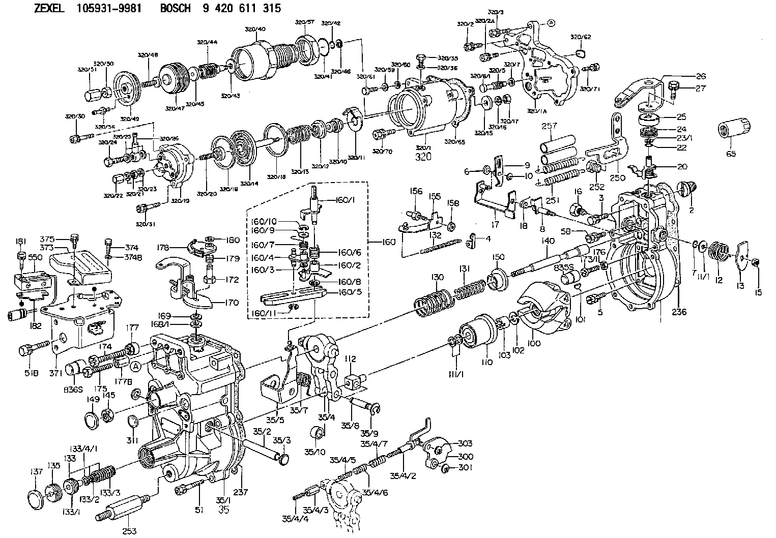
Information governor
BOSCH
9 420 611 315
9420611315
ZEXEL
105931-9981
1059319981
ISUZU
8971058031
8971058031
Rating:
Scheme ###:
| 1. | [1] | 159200-4720 | GOVERNOR HOUSING |
| 2. | [1] | 154007-0200 | ADAPTOR |
| 3. | [1] | 020018-1840 | BLEEDER SCREW M8P1.25L18 |
| 4. | [1] | 159232-1600 | PLATE |
| 5. | [5] | 029010-6810 | BLEEDER SCREW |
| 5B. | [1] | 020106-1640 | BLEEDER SCREW M6P1.0L14 |
| 6. | [1] | 159242-0600 | BUSHING |
| 7. | [1] | 016530-1010 | O-RING |
| 8. | [1] | 159205-2321 | LEVER SHAFT |
| 9. | [1] | 159202-5601 | CONTROL LEVER |
| 10. | [1] | 016010-0810 | LOCKING WASHER |
| 11/1. | [0] | 029311-0220 | SHIM D18&10.3T0.2 |
| 11/1. | [0] | 029311-0230 | SHIM D18&10.3T0.5 |
| 11/1. | [0] | 029311-0430 | SHIM D18&10.3T0.30 |
| 11/1. | [0] | 029311-0440 | SHIM D18&10.3T0.40 |
| 11/1. | [0] | 029311-0450 | SHIM D18&10.3T0.25 |
| 11/1. | [0] | 029311-0460 | SHIM D18&10.3T0.35 |
| 11/1. | [0] | 139410-3300 | SHIM D18&10.3T0.6 |
| 11/1. | [0] | 139410-3400 | SHIM D18&10.3T0.8 |
| 11/1. | [0] | 139410-3500 | SHIM D18&10.3T0.9 |
| 12. | [1] | 159215-0000 | COILED SPRING |
| 13. | [1] | 159242-6601 | CONTROL LEVER |
| 15. | [1] | 013020-8040 | UNION NUT M8P1.25H7 |
| 16. | [1] | 159237-5500 | CAPSULE |
| 17. | [1] | 159202-5220 | CONTROL LEVER |
| 18. | [1] | 159215-0300 | COILED SPRING |
| 20. | [1] | 159242-7120 | CONTROL LEVER |
| 22. | [1] | 029631-0030 | O-RING &9.8W2.3 |
| 23/1. | [0] | 139410-1300 | SHIM D20.8&10.2T0.3 |
| 23/1. | [0] | 139410-1700 | SHIM D20.8&10.2T0.2 |
| 23/1. | [0] | 139410-1800 | SHIM D20.8&10.2T0.4 |
| 23/1. | [0] | 139410-2800 | SHIM D20.8&10.2T0.6 |
| 23/1. | [0] | 139410-3700 | SHIM D20.8&10.2T0.9 |
| 24. | [1] | 159215-4200 | COILED SPRING |
| 25. | [1] | 159235-6500 | CAP |
| 26. | [1] | 159290-9820 | CONTROL LEVER |
| 27. | [1] | 020006-1640 | BLEEDER SCREW M6P1L16 4T |
| 35. | [1] | 159250-1320 | GOVERNOR COVER |
| 35/1. | [1] | 159201-7020 | GOVERNOR COVER |
| 35/2. | [1] | 159205-0400 | LEVER SHAFT |
| 35/3. | [2] | 159237-0200 | CAPSULE |
| 35/4. | [1] | 159253-2720 | TENSIONING LEVER |
| 35/4/2. | [1] | 159204-6022 | RACK |
| 35/4/3. | [1] | 159233-0300 | UNION NUT |
| 35/4/4. | [1] | 159234-0300 | FLAT-HEAD SCREW |
| 35/4/5. | [1] | 159216-0000 | COILED SPRING |
| 35/4/6. | [1] | 159216-0100 | COILED SPRING |
| 35/4/7. | [1] | 159216-0700 | COILED SPRING |
| 35/5. | [1] | 159203-6120 | GUIDE LEVER |
| 35/7. | [1] | 159215-1701 | COILED SPRING |
| 35/8. | [1] | 159231-1300 | BEARING PIN |
| 35/9. | [2] | 016010-0610 | LOCKING WASHER |
| 35/10. | [1] | 159238-2900 | BUSHING |
| 51. | [6] | 020106-3840 | BLEEDER SCREW |
| 51B. | [1] | 020106-4540 | BLEEDER SCREW M6P1.0L45 |
| 65. | [1] | 155404-5700 | CAP |
| 100. | [1] | 154100-9520 | FLYWEIGHT ASSEMBLY |
| 101. | [1] | 025803-1610 | WOODRUFF KEY |
| 102. | [1] | 029321-2020 | LOCKING WASHER |
| 103. | [1] | 029231-2030 | UNION NUT |
| 110. | [1] | 154123-2320 | SLIDING PIECE |
| 111/1. | [0] | 029311-0010 | SHIM D14&10.1T0.2 |
| 111/1. | [0] | 029311-0180 | SHIM D14&10.1T0.3 |
| 111/1. | [0] | 029311-0190 | SHIM D14&10.1T0.40 |
| 111/1. | [0] | 029311-0210 | SHIM D14&10.1T1 |
| 111/1. | [0] | 139410-0000 | SHIM D14.0&10.1T0.5 |
| 111/1. | [0] | 139410-0100 | SHIM D14.0&10.1T1.5 |
| 111/1. | [0] | 139410-3000 | SHIM D14&10.1T2.0 |
| 111/1. | [0] | 139410-3100 | SHIM D14&10.1T3.0 |
| 111/1. | [0] | 139410-3200 | SHIM D14&10.1T4.0 |
| 112. | [1] | 159236-0200 | TERMINAL STUD |
| 130. | [1] | 159210-1000 | GOVERNOR SPRING |
| 131. | [1] | 159211-1100 | GOVERNOR SPRING |
| 132. | [1] | 159214-0300 | COILED SPRING |
| 133. | [1] | 159212-3520 | SPRING PACK |
| 133/1. | [1] | 159234-5602 | GUIDE SLEEVE |
| 133/2. | [1] | 159212-3300 | COILED SPRING |
| 133/3. | [1] | 159212-3500 | COILED SPRING |
| 133/4/1. | [0] | 029310-9240 | SHIM D11.9&9T0.1 |
| 133/4/1. | [0] | 029310-9250 | SHIM D11.9&9T0.2 |
| 133/4/1. | [0] | 029310-9260 | SHIM D11.9&9T0.25 |
| 133/4/1. | [0] | 029310-9270 | SHIM D11.9&9T1.0 |
| 133/4/1. | [0] | 139409-0100 | SHIM D11.9&9T0.3 |
| 133/4/1. | [0] | 139409-0200 | SHIM D11.9&9T0.5 |
| 133/4/1. | [0] | 139409-0300 | SHIM D11.5&9T0.8 |
| 135. | [1] | 159248-2700 | FLAT-HEAD SCREW |
| 137. | [1] | 159237-5300 | CAPSULE |
| 140. | [1] | 159205-2101 | LEVER SHAFT |
| 145. | [1] | 159233-5700 | UNION NUT |
| 149. | [1] | 159237-5400 | CAPSULE |
| 150. | [1] | 159235-5300 | SLOTTED WASHER |
| 155. | [1] | 159204-5920 | STRAP |
| 156. | [1] | 159233-6020 | BLEEDER SCREW |
| 158. | [1] | 013020-5240 | UNION NUT M5P0.8H4 |
| 160. | [1] | 159252-2221 | LEVER GROUP |
| 160/1. | [1] | 159205-3711 | LEVER SHAFT |
| 160/2. | [1] | 159202-4810 | CONTROL LEVER |
| 160/3. | [1] | 029310-6030 | SHIM D11.5&6.2T0.2 |
| 160/4. | [1] | 159202-4520 | CONTROL LEVER |
| 160/5. | [1] | 159202-2200 | CONTROL LEVER |
| 160/6. | [1] | 159215-2301 | COILED SPRING |
| 160/7. | [1] | 159215-3900 | COILED SPRING |
| 160/8. | [1] | 016010-0810 | LOCKING WASHER |
| 160/9. | [1] | 014020-6140 | PLAIN WASHER |
| 160/10. | [1] | 016010-0610 | LOCKING WASHER |
| 160/11. | [1] | 016010-0810 | LOCKING WASHER |
| 168/1. | [0] | 139410-1200 | SHIM D26&10.2T0.3 |
| 168/1. | [0] | 139410-1900 | SHIM D26&10.2T0.2 |
| 168/1. | [0] | 139410-2000 | SHIM D26&10.2T0.4 |
| 168/1. | [0] | 139410-2400 | SHIM D26&10.2T0.35 |
| 168/1. | [0] | 139410-2500 | SHIM D26&10.2T0.25 |
| 168/1. | [0] | 139410-2900 | SHIM D26&10.2T0.6 |
| 169. | [1] | 139410-2100 | SHIM |
| 170. | [1] | 159264-3420 | CONTROL LEVER |
| 172. | [1] | 159235-6100 | UNION NUT |
| 173/1. | [1] | 139006-3500 | BLEEDER SCREW M6P1.0L33 |
| 173/1. | [1] | 139006-3700 | BLEEDER SCREW M6P1.0L34 |
| 173/1. | [1] | 139006-3800 | BLEEDER SCREW M6P1.0L35 |
| 173/1. | [1] | 139006-3900 | BLEEDER SCREW M6P1.0L36 |
| 173/1. | [1] | 139006-5300 | BLEEDER SCREW M6P1.0L31 |
| 173/1. | [1] | 139006-5400 | BLEEDER SCREW M6P1.0L32 |
| 173/1. | [1] | 155615-2500 | BLEEDER SCREW M6P1.0L37 |
| 174. | [1] | 154010-7200 | BLEEDER SCREW M8P1.25L62 |
| 174B. | [1] | 154010-8100 | BLEEDER SCREW M8P1.25L65 |
| 175. | [1] | 154012-4700 | BLEEDER SCREW |
| 176. | [1] | 159225-8600 | UNION NUT |
| 177. | [1] | 154011-2300 | UNION NUT |
| 177B. | [1] | 154011-3500 | UNION NUT |
| 178. | [1] | 159265-9400 | CONTROL LEVER |
| 179. | [1] | 159215-5000 | COILED SPRING |
| 180. | [1] | 016010-0640 | LOCKING WASHER |
| 181. | [2] | 020104-2540 | BLEEDER SCREW |
| 182. | [1] | 159220-1400 | PLATE |
| 236. | [1] | 154390-0000 | GASKET |
| 237. | [1] | 159238-3100 | GASKET |
| 250. | [1] | 159228-4920 | BRACKET |
| 251. | [2] | 159243-4800 | COILED SPRING |
| 252. | [1] | 159248-0200 | BLEEDER SCREW |
| 253. | [1] | 159248-0401 | BLEEDER SCREW |
| 257. | [2] | 154156-0500 | TUBE |
| 300. | [1] | 159285-4500 | CAM PLATE |
| 301. | [1] | 016010-0840 | LOCKING WASHER |
| 303. | [1] | 016010-0540 | LOCKING WASHER |
| 311. | [1] | 159237-0200 | CAPSULE |
| 320. | [1] | 154420-5720 | COMPENSATOR,MANIFOLD-PRES |
| 320/1. | [1] | 154413-5421 | DIAPHRAGM HOUSING |
| 320/1A. | [1] | 154413-5501 | SPACER BUSHING |
| 320/2. | [2] | 020106-2240 | BLEEDER SCREW |
| 320/2A. | [1] | 020106-2540 | BLEEDER SCREW M6P1L25 |
| 320/3. | [1] | 020118-3240 | BLEEDER SCREW |
| 320/5. | [1] | 159275-1400 | COILED SPRING |
| 320/6/1. | [1] | 159274-0120 | STOP PIN L125 |
| 320/6/1. | [1] | 159274-0220 | STOP PIN L127.50 |
| 320/6/1. | [1] | 159274-0320 | STOP PIN L128.00 |
| 320/6/1. | [1] | 159274-0420 | STOP PIN L127.00 |
| 320/6/1. | [1] | 159274-0520 | STOP PIN L126.00 |
| 320/6/1. | [1] | 159274-0620 | STOP PIN L129.00 |
| 320/6/1. | [1] | 159274-0720 | STOP PIN L128.50 |
| 320/6/1. | [1] | 159274-0820 | STOP PIN L125.50 |
| 320/6/1. | [1] | 159274-0920 | STOP PIN L126.50 |
| 320/6/1. | [1] | 159274-1120 | STOP PIN L119.5 |
| 320/6/1. | [1] | 159274-1220 | STOP PIN L120 |
| 320/6/1. | [1] | 159274-1320 | STOP PIN L120.5 |
| 320/6/1. | [1] | 159274-1420 | STOP PIN L121 |
| 320/6/1. | [1] | 159274-1520 | STOP PIN L121.5 |
| 320/6/1. | [1] | 159274-1620 | STOP PIN L122 |
| 320/6/1. | [1] | 159274-1720 | STOP PIN L122.5 |
| 320/6/1. | [1] | 159274-1820 | STOP PIN L123 |
| 320/6/1. | [1] | 159274-1920 | STOP PIN L123.5 |
| 320/6/1. | [1] | 159274-4220 | STOP PIN L129.5 |
| 320/6/1. | [1] | 159274-4320 | STOP PIN L130 |
| 320/6/1. | [1] | 159274-4420 | STOP PIN L130.5 |
| 320/6/1. | [1] | 159274-4520 | STOP PIN L131 |
| 320/6/1. | [1] | 159274-4620 | STOP PIN L131.5 |
| 320/6/1. | [1] | 159274-4720 | STOP PIN L132 |
| 320/6/1. | [1] | 159274-4820 | STOP PIN L132.5 |
| 320/6/1. | [1] | 159274-4920 | STOP PIN L133 |
| 320/6/1. | [1] | 159274-5020 | STOP PIN L133.5 |
| 320/7. | [1] | 014010-5140 | PLAIN WASHER D12&5.5T0.8 |
| 320/10. | [1] | 154415-1200 | BUSHING |
| 320/11. | [1] | 146711-0000 | PLATE |
| 320/12. | [1] | 154415-1300 | UNION NUT |
| 320/13. | [1] | 154402-3400 | COILED SPRING |
| 320/14. | [1] | 154413-3820 | DIAPHRAGM |
| 320/15. | [1] | 154406-5500 | SLOTTED WASHER |
| 320/16. | [1] | 014110-6440 | LOCKING WASHER |
| 320/17. | [1] | 013030-6010 | UNION NUT |
| 320/18. | [2] | 154413-2600 | GASKET |
| 320/18. | [2] | 154413-2600 | GASKET |
| 320/19. | [1] | 154404-5000 | COVER |
| 320/20. | [1] | 154413-4000 | FLAT-HEAD SCREW |
| 320/21. | [1] | 013030-6040 | UNION NUT M6P1H3.6 |
| 320/22. | [1] | 154035-1600 | CAP NUT |
| 320/23. | [2] | 139506-0300 | GASKET |
| 320/24. | [1] | 029731-0180 | EYE BOLT |
| 320/25. | [2] | 139510-0200 | GASKET |
| 320/26. | [1] | 154412-7920 | JOINT CONNECTION |
| 320/30. | [1] | 020106-3040 | BLEEDER SCREW |
| 320/31. | [2] | 029010-6540 | BLEEDER SCREW |
| 320/35. | [1] | 029111-2090 | CAPSULE |
| 320/36. | [1] | 139512-0000 | GASKET D17.2&12.2T1.0 |
| 320/40. | [1] | 154413-5321 | DIAPHRAGM HOUSING |
| 320/41. | [1] | 016500-2400 | O-RING |
| 320/42. | [1] | 016500-0810 | O-RING |
| 320/43. | [1] | 029311-6020 | SHIM |
| 320/44. | [1] | 155423-9800 | COILED SPRING |
| 320/45. | [1] | 154413-5100 | STOP PIN |
| 320/46. | [1] | 016010-0640 | LOCKING WASHER |
| 320/47. | [1] | 155403-3021 | BELLOWS |
| 320/48. | [1] | 155423-1500 | SCREW PLUG |
| 320/49. | [1] | 155423-2000 | COVER |
| 320/50. | [1] | 029240-6010 | UNION NUT M6P1.0H5* |
| 320/51. | [1] | 154035-1600 | CAP NUT |
| 320/56. | [1] | 139805-0000 | JOINT CONNECTION |
| 320/57. | [1] | 154413-4500 | UNION NUT |
| 320/59. | [1] | 014010-6140 | PLAIN WASHER D13&6.5T1 |
| 320/60. | [1] | 139505-0000 | PLAIN WASHER |
| 320/61. | [1] | 010006-1670 | BLEEDER SCREW M6P1L16 7T |
| 320/62. | [1] | 159226-4500 | SPACER RING |
| 320/65. | [1] | 154390-3900 | GASKET |
| 320/70. | [2] | 020106-2040 | BLEEDER SCREW M6P1L20 |
| 320/71. | [3] | 020106-2240 | BLEEDER SCREW |
| 371. | [1] | 159220-1520 | BRACKET |
| 373. | [1] | 159228-0120 | COVER |
| 374. | [2] | 020105-0840 | BLEEDER SCREW M5P0.5L8 |
| 374B. | [2] | 014020-5140 | PLAIN WASHER D10&5.5T0.8 |
| 375. | [1] | 020146-1240 | BLEEDER SCREW M6P1.0L12 |
| 550. | [1] | 153169-4522 | MICROSWITCH |
Include in #1:
101481-0211
as GOVERNOR
Cross reference number
Zexel num
Bosch num
Firm num
Name
Information:
Introduction
Note: Do not perform any procedure in this Special Instruction until the information has been read and understood.Injector Wiring Harness Kit
The new 141-7060 Injector Wiring Harness Kit is available to repair the connectors on the 122-8835 Wiring Harness Assembly or the 133-3745 Wiring Harness Assembly . The connectors on the wiring harness assembly connect to the Hydraulic Electronic Unit Injectors (HEUI) in the above Caterpillar Truck Engines. Each injector wiring harness kit includes:
one connector
two barrel splices
two pieces of heat shrink tubingInstallation Of The 141-7060 Injector Wiring Harness Kit
Carefully remove the valve cover from the engine. Avoid damaging the gasket on the valve cover.
Remove the damaged connector from the HEUI injector solenoid.
Cut the damaged connector from the HEUI injector wiring harness. A length of 31.8 mm (1.25 inch) should remain from the heat shrink tubing on one of the harness wires. A length of 19.1 mm (0.75 inch) should remain from the heat shrink tubing on the other harness wire.Note: DO NOT allow the removed insulation to fall into the cylinder head assembly. DO NOT allow the removed insulation to fall into the open passages of the oil sump.
Remove approximately 8 mm (0.3 inch) of the insulation from the two harness wires.Note: Remove only enough insulation in order to allow the harness wires to seat into the new barrel splice from the injector wiring harness kit.
Remove the two pieces of the heat shrink tubing from the injector wiring harness kit.
Slip the heat shrink tubing from the injector wiring harness kit over the ends of the HEUI injector wiring harness wires.Note: The heat shrink tubing must be pushed far enough onto the harness wires so that the heat shrink tubing will not be cut when crimping the barrel splices. DO NOT crimp through the heat shrink tubing. Crimping through the heat shrink tubing will cause damage.
Remove the replacement connector from the injector wiring harness kit.
Install the replacement connector on the HEUI injector wiring harness wires.
Crimp the two barrel splices to the HEUI injector wiring harness wires.
Move the heat shrink tubing over the exposed barrel splices. Center the barrel splices in the heat shrink tubing.
Use a heat gun to heat the heat shrink tubing. Apply heat until the tubing shrinks evenly around the barrel splices.Note: DO NOT overheat the heat shrink tubing. Damage to the heat shrink tubing may result. The appearance of the heat shrink tubing should be uniform and smooth when properly shrunk.
Connect the repaired HEUI injector wiring harness connector to the HEUI injector solenoid.
Inspect the valve cover gasket for damage. Replace the valve cover gasket if the gasket is damaged.
Install the valve cover gasket. Install the valve cover.
Start the engine. Test the effectiveness of the repair.