Information governor
BOSCH
9 420 613 065
9420613065
ZEXEL
105931-8971
1059318971
ISUZU
8970645720
8970645720
Rating:
Scheme ###:
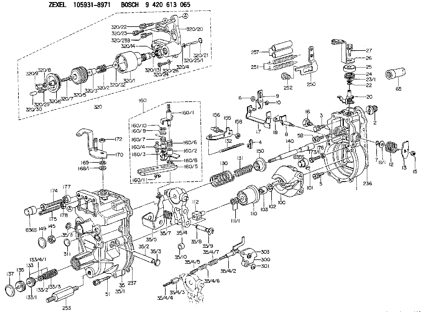
| 1. | [1] | 159200-4720 | GOVERNOR HOUSING |
| 2. | [1] | 154007-0200 | ADAPTOR |
| 3. | [1] | 020018-1840 | BLEEDER SCREW M8P1.25L18 |
| 4. | [1] | 159232-1600 | PLATE |
| 5. | [5] | 029010-6810 | BLEEDER SCREW |
| 5B. | [1] | 020106-1640 | BLEEDER SCREW M6P1.0L14 |
| 6. | [1] | 159242-0600 | BUSHING |
| 7. | [1] | 016530-1010 | O-RING |
| 8. | [1] | 159205-2321 | LEVER SHAFT |
| 9. | [1] | 159202-5601 | CONTROL LEVER |
| 10. | [1] | 016010-0810 | LOCKING WASHER |
| 11/1. | [0] | 029311-0220 | SHIM D18&10.3T0.2 |
| 11/1. | [0] | 029311-0230 | SHIM D18&10.3T0.5 |
| 11/1. | [0] | 029311-0430 | SHIM D18&10.3T0.30 |
| 11/1. | [0] | 029311-0440 | SHIM D18&10.3T0.40 |
| 11/1. | [0] | 029311-0450 | SHIM D18&10.3T0.25 |
| 11/1. | [0] | 029311-0460 | SHIM D18&10.3T0.35 |
| 11/1. | [0] | 139410-3300 | SHIM D18&10.3T0.6 |
| 11/1. | [0] | 139410-3400 | SHIM D18&10.3T0.8 |
| 11/1. | [0] | 139410-3500 | SHIM D18&10.3T0.9 |
| 12. | [1] | 159215-0000 | COILED SPRING |
| 13. | [1] | 159242-6601 | CONTROL LEVER |
| 15. | [1] | 013020-8040 | UNION NUT M8P1.25H7 |
| 16. | [1] | 159237-5500 | CAPSULE |
| 17. | [1] | 159202-5220 | CONTROL LEVER |
| 18. | [1] | 159215-0300 | COILED SPRING |
| 20. | [1] | 159242-7120 | CONTROL LEVER |
| 22. | [1] | 029631-0030 | O-RING &9.8W2.3 |
| 23/1. | [0] | 139410-1300 | SHIM D20.8&10.2T0.3 |
| 23/1. | [0] | 139410-1700 | SHIM D20.8&10.2T0.2 |
| 23/1. | [0] | 139410-1800 | SHIM D20.8&10.2T0.4 |
| 23/1. | [0] | 139410-2800 | SHIM D20.8&10.2T0.6 |
| 23/1. | [0] | 139410-3700 | SHIM D20.8&10.2T0.9 |
| 24. | [1] | 159215-4200 | COILED SPRING |
| 25. | [1] | 159235-6500 | CAP |
| 26. | [1] | 159249-8620 | CONTROL LEVER |
| 27. | [1] | 020006-1640 | BLEEDER SCREW M6P1L16 4T |
| 35. | [1] | 159250-1620 | GOVERNOR COVER |
| 35/1. | [1] | 159201-5221 | GOVERNOR COVER |
| 35/2. | [1] | 159205-0400 | LEVER SHAFT |
| 35/3. | [2] | 159237-0200 | CAPSULE |
| 35/3. | [2] | 159237-0200 | CAPSULE |
| 35/4. | [1] | 159253-2720 | TENSIONING LEVER |
| 35/4/2. | [1] | 159204-6022 | RACK |
| 35/4/3. | [1] | 159233-0300 | UNION NUT |
| 35/4/4. | [1] | 159234-0300 | FLAT-HEAD SCREW |
| 35/4/5. | [1] | 159216-0000 | COILED SPRING |
| 35/4/6. | [1] | 159216-0100 | COILED SPRING |
| 35/4/7. | [1] | 159216-0700 | COILED SPRING |
| 35/5. | [1] | 159203-6120 | GUIDE LEVER |
| 35/7. | [1] | 159215-1701 | COILED SPRING |
| 35/8. | [1] | 159231-1300 | BEARING PIN |
| 35/9. | [2] | 016010-0610 | LOCKING WASHER |
| 35/10. | [1] | 159238-2900 | BUSHING |
| 51. | [7] | 020106-3840 | BLEEDER SCREW |
| 65. | [1] | 154050-1720 | STOPPING DEVICE |
| 100. | [1] | 154100-9520 | FLYWEIGHT ASSEMBLY |
| 101. | [1] | 025803-1610 | WOODRUFF KEY |
| 102. | [1] | 029321-2020 | LOCKING WASHER |
| 103. | [1] | 029231-2030 | UNION NUT |
| 110. | [1] | 154123-2320 | SLIDING PIECE |
| 111/1. | [0] | 029311-0010 | SHIM D14&10.1T0.2 |
| 111/1. | [0] | 029311-0180 | SHIM D14&10.1T0.3 |
| 111/1. | [0] | 029311-0190 | SHIM D14&10.1T0.40 |
| 111/1. | [0] | 029311-0210 | SHIM D14&10.1T1 |
| 111/1. | [0] | 139410-0000 | SHIM D14.0&10.1T0.5 |
| 111/1. | [0] | 139410-0100 | SHIM D14.0&10.1T1.5 |
| 111/1. | [0] | 139410-3000 | SHIM D14&10.1T2.0 |
| 111/1. | [0] | 139410-3100 | SHIM D14&10.1T3.0 |
| 111/1. | [0] | 139410-3200 | SHIM D14&10.1T4.0 |
| 112. | [1] | 159236-0200 | TERMINAL STUD |
| 130. | [1] | 159210-6700 | GOVERNOR SPRING |
| 131. | [1] | 159211-3400 | GOVERNOR SPRING |
| 132. | [1] | 159214-0300 | COILED SPRING |
| 133. | [1] | 159212-6420 | SPRING PACK |
| 133/1. | [1] | 159234-5602 | GUIDE SLEEVE |
| 133/2. | [1] | 159212-5500 | COILED SPRING |
| 133/3. | [1] | 159212-6401 | COILED SPRING |
| 133/4/1. | [0] | 029310-9240 | SHIM D11.9&9T0.1 |
| 133/4/1. | [0] | 029310-9250 | SHIM D11.9&9T0.2 |
| 133/4/1. | [0] | 029310-9260 | SHIM D11.9&9T0.25 |
| 133/4/1. | [0] | 029310-9270 | SHIM D11.9&9T1.0 |
| 133/4/1. | [0] | 139409-0100 | SHIM D11.9&9T0.3 |
| 133/4/1. | [0] | 139409-0200 | SHIM D11.9&9T0.5 |
| 133/4/1. | [0] | 139409-0300 | SHIM D11.5&9T0.8 |
| 135. | [1] | 159248-2700 | FLAT-HEAD SCREW |
| 137. | [1] | 159237-5300 | CAPSULE |
| 140. | [1] | 159205-2101 | LEVER SHAFT |
| 145. | [1] | 159233-5700 | UNION NUT |
| 149. | [1] | 159237-5400 | CAPSULE |
| 150. | [1] | 159235-5300 | SLOTTED WASHER |
| 155. | [1] | 159204-5920 | STRAP |
| 156. | [1] | 159233-6020 | BLEEDER SCREW |
| 158. | [1] | 013020-5240 | UNION NUT M5P0.8H4 |
| 160. | [1] | 159252-2221 | LEVER GROUP |
| 160/1. | [1] | 159205-3711 | LEVER SHAFT |
| 160/2. | [1] | 159202-4810 | CONTROL LEVER |
| 160/3. | [1] | 029310-6030 | SHIM D11.5&6.2T0.2 |
| 160/4. | [1] | 159202-4520 | CONTROL LEVER |
| 160/5. | [1] | 159202-2200 | CONTROL LEVER |
| 160/6. | [1] | 159215-2301 | COILED SPRING |
| 160/7. | [1] | 159215-3900 | COILED SPRING |
| 160/8. | [1] | 016010-0810 | LOCKING WASHER |
| 160/9. | [1] | 014020-6140 | PLAIN WASHER |
| 160/10. | [1] | 016010-0610 | LOCKING WASHER |
| 160/11. | [1] | 016010-0810 | LOCKING WASHER |
| 168/1. | [0] | 139410-1200 | SHIM D26&10.2T0.3 |
| 168/1. | [0] | 139410-1900 | SHIM D26&10.2T0.2 |
| 168/1. | [0] | 139410-2000 | SHIM D26&10.2T0.4 |
| 168/1. | [0] | 139410-2400 | SHIM D26&10.2T0.35 |
| 168/1. | [0] | 139410-2500 | SHIM D26&10.2T0.25 |
| 168/1. | [0] | 139410-2900 | SHIM D26&10.2T0.6 |
| 169. | [1] | 139410-2100 | SHIM |
| 170. | [1] | 159241-1020 | CONTROL LEVER |
| 172. | [1] | 013020-8040 | UNION NUT M8P1.25H7 |
| 173/1. | [1] | 139006-3500 | BLEEDER SCREW M6P1.0L33 |
| 173/1. | [1] | 139006-3700 | BLEEDER SCREW M6P1.0L34 |
| 173/1. | [1] | 139006-3800 | BLEEDER SCREW M6P1.0L35 |
| 173/1. | [1] | 139006-3900 | BLEEDER SCREW M6P1.0L36 |
| 173/1. | [1] | 139006-5300 | BLEEDER SCREW M6P1.0L31 |
| 173/1. | [1] | 139006-5400 | BLEEDER SCREW M6P1.0L32 |
| 173/1. | [1] | 155615-2500 | BLEEDER SCREW M6P1.0L37 |
| 174. | [1] | 154010-8100 | BLEEDER SCREW M8P1.25L65 |
| 175. | [1] | 154010-0100 | FLAT-HEAD SCREW |
| 176. | [1] | 159225-8600 | UNION NUT |
| 177. | [1] | 154011-2300 | UNION NUT |
| 178. | [1] | 154011-0100 | HEXAGON NUT |
| 236. | [1] | 154390-0000 | GASKET |
| 237. | [1] | 159238-3100 | GASKET |
| 250. | [1] | 159228-4920 | BRACKET |
| 251. | [2] | 159243-4800 | COILED SPRING |
| 252. | [1] | 159248-0200 | BLEEDER SCREW |
| 253. | [1] | 159248-0401 | BLEEDER SCREW |
| 257. | [2] | 154156-0500 | TUBE |
| 300. | [1] | 159280-4000 | CAM PLATE |
| 301. | [1] | 016010-0840 | LOCKING WASHER |
| 303. | [1] | 016010-0540 | LOCKING WASHER |
| 311. | [1] | 159237-0200 | CAPSULE |
| 320. | [1] | 155424-5120 | ANEROID CAPSULE |
| 320/1. | [1] | 155423-7520 | DIAPHRAGM HOUSING |
| 320/2. | [1] | 155423-2900 | COILED SPRING |
| 320/3. | [1] | 155423-1800 | STOP PIN |
| 320/4. | [1] | 016010-0640 | LOCKING WASHER |
| 320/5. | [1] | 155403-3021 | BELLOWS |
| 320/6. | [1] | 155423-2000 | COVER |
| 320/7. | [1] | 155423-1500 | SCREW PLUG |
| 320/8. | [1] | 029240-6010 | UNION NUT M6P1.0H5* |
| 320/9. | [1] | 154035-1600 | CAP NUT |
| 320/13. | [1] | 016520-1510 | O-RING |
| 320/14. | [1] | 139220-0100 | UNION NUT |
| 320/20. | [1] | 155423-1701 | SPACER BUSHING |
| 320/21. | [1] | 159226-4500 | SPACER RING |
| 320/22. | [1] | 020118-3040 | BLEEDER SCREW |
| 320/23. | [3] | 020106-2240 | BLEEDER SCREW |
| 320/23B. | [1] | 020106-2540 | BLEEDER SCREW M6P1L25 |
| 320/24. | [1] | 139006-0900 | BLEEDER SCREW |
| 320/25/1. | [1] | 155423-1200 | STOP PIN L102 |
| 320/25/1. | [1] | 155424-4900 | STOP PIN L95 |
| 320/25/1. | [1] | 155424-5000 | STOP PIN L96 |
| 320/25/1B. | [1] | 155423-1300 | STOP PIN L102.5 |
| 320/25/1C. | [1] | 155423-1400 | STOP PIN L103 |
| 320/25/1D. | [1] | 155423-7600 | STOP PIN L103.5 |
| 320/25/1E. | [1] | 155423-7700 | STOP PIN L104 |
| 320/25/1F. | [1] | 155423-8700 | STOP PIN L97 |
| 320/25/1G. | [1] | 155423-8800 | STOP PIN L98 |
| 320/25/1H. | [1] | 155423-8900 | STOP PIN L99 |
| 320/25/1I. | [1] | 155423-9000 | STOP PIN L100 |
| 320/25/1J. | [1] | 155423-9100 | STOP PIN L101 |
| 320/26. | [1] | 014110-6440 | LOCKING WASHER |
| 320/29. | [1] | 139805-0000 | JOINT CONNECTION |
| 320/30. | [1] | 155424-0300 | CAP |
| 320/32. | [1] | 029311-2060 | SHIM D22&12.5T0.5 |
Cross reference number
Zexel num
Bosch num
Firm num
Name
Information:
Cruise Control On/Off Input Circuit
The cruise control (CC) and power take-off (PTO) ON/OFF input is an ordinary switch. With this switch in the ON position, it is possible to "activate" the cruise control or power take-off mode if other ECM programmed conditions are met.With this switch "open" (or OFF), the input line to the ECM will go to approximately 5 volts. With the switch "closed" (or ON), the input line to the ECM will go to 0 volts (ground).Cruise Control Set/Resume Input Circuit
The cruise control and power take-off set/resume is provided by a three position switch. The switch is used to SET vehicle speed or engine rpm. The function of each position of the switch is as follows:1) CENTER POSITION, the set/resume switch is "open" and all inputs are inactive.2) SET POSITION, after the switch is moved to the SET position and released, the ECM will maintain the existing engine rpm (determining vehicle speed) when the switch was released. If the engine is held in the SET position, the ECM will gradually increase engine rpm (determining vehicle speed) until the switch is released.3) RESUME POSITION, if cruise is deactivated by application of the clutch or service brake, and the switch is then moved to the RESUME position and released, the cruise (PTO) mode is reactivated to the last setting. If the switch is held in the RESUME position, the ECM will gradually decrease engine rpm (determining vehicle speed) until the switch is released.With this switch "open" (or OFF), the input line to the ECM will go to approximately 5 volts. With the switch "closed" (or ON), the input line to the ECM will go to 0 volts (ground).Vehicle Switches Input Circuits
The brake switch is used to deactivate the cruise or PTO modes when the vehicle service brakes are applied. The brake switch is also used to activate the retarder enable output if the service brakes are applied while in cruise mode.The clutch switch is used to deactivate the cruise or PTO modes when the clutch pedal is pressed. The clutch switch is used to DEACTIVATE the retarder enable circuit.With this switch "open" (or OFF), the input line to the ECM will go to approximately 5 volts. With the switch "closed" (or ON), the input line to the ECM will go to 0 volts (ground).Fuel Pressure Input Circuit
Fuel pressure is monitored after the filter by the fuel pressure sensor which is located on the fuel filter housing. The 5 Volt DC operating voltage for this sensor is supplied by the ECM. The output of the fuel pressure sensor is a .5 to 4.5 Volts DC signal. The voltage is dependent upon fuel pressure and is interpreted by the ECM as fuel pressure. If fuel pressure is less than 445 kPa (65 psi) at rated rpm, the "check engine" light is turned on.Engine Electrical System
The electrical system can have three separate circuits: the charging circuit, the starting circuit and the low amperage circuit. Some of the electrical system components are