Information governor
BOSCH
9 420 612 682
9420612682
ZEXEL
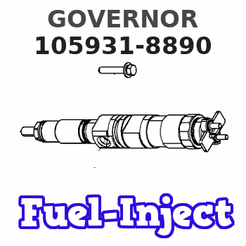
105931-8890
1059318890
ISUZU
1157706010
1157706010
Rating:
Scheme ###:
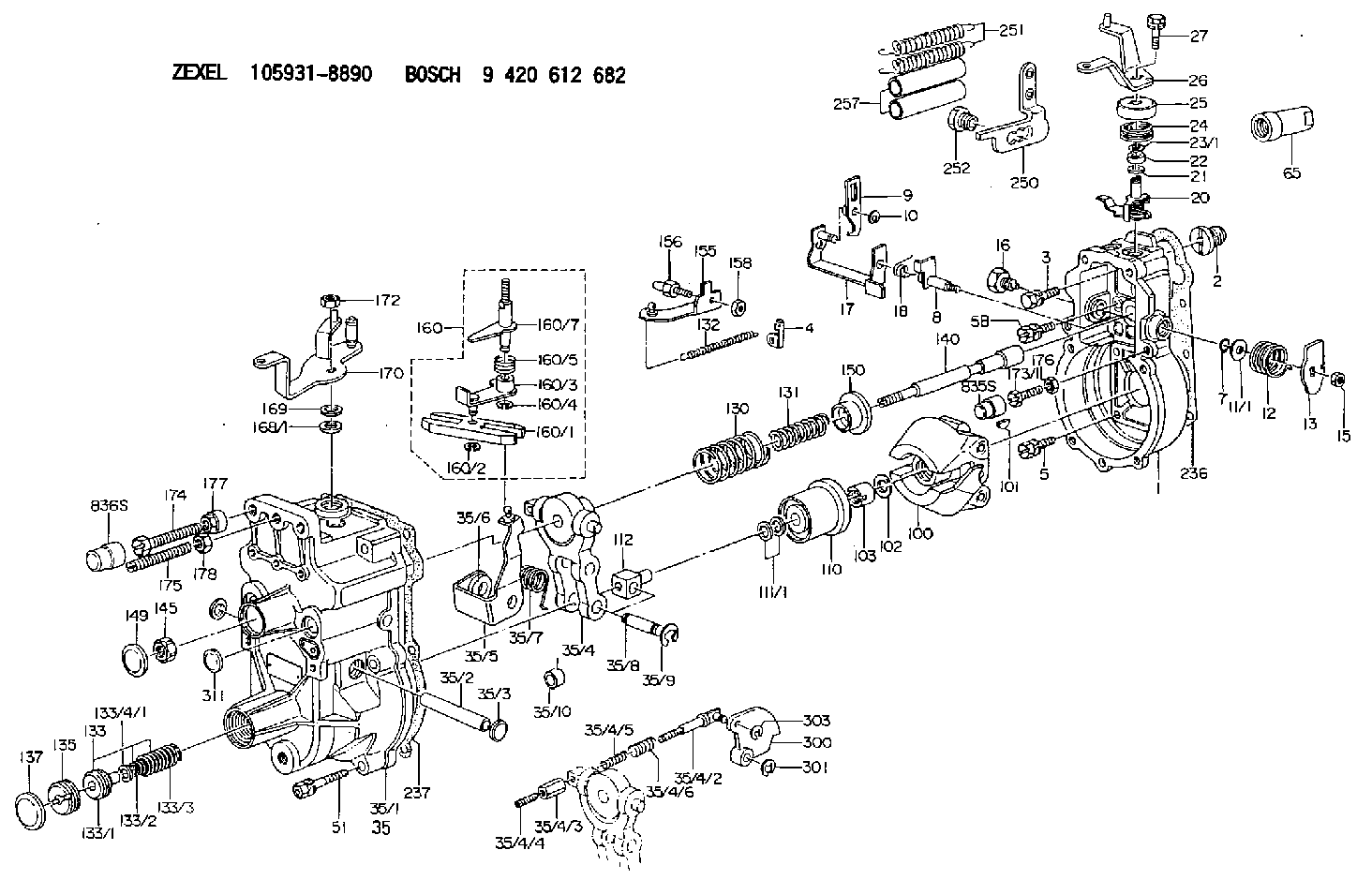
| 1. | [1] | 159200-5020 | GOVERNOR HOUSING |
| 2. | [1] | 154007-0200 | ADAPTOR |
| 3. | [1] | 020018-1840 | BLEEDER SCREW M8P1.25L18 |
| 4. | [1] | 159232-0201 | PLATE |
| 5. | [5] | 029010-6810 | BLEEDER SCREW |
| 5B. | [1] | 020106-1640 | BLEEDER SCREW M6P1.0L14 |
| 7. | [1] | 139710-0200 | O-RING |
| 8. | [1] | 159205-2321 | LEVER SHAFT |
| 9. | [1] | 159202-5101 | CONTROL LEVER |
| 10. | [1] | 016010-0810 | LOCKING WASHER |
| 11/1. | [0] | 029311-0220 | SHIM D18&10.3T0.2 |
| 11/1. | [0] | 029311-0230 | SHIM D18&10.3T0.5 |
| 11/1. | [0] | 029311-0430 | SHIM D18&10.3T0.30 |
| 11/1. | [0] | 029311-0440 | SHIM D18&10.3T0.40 |
| 11/1. | [0] | 029311-0450 | SHIM D18&10.3T0.25 |
| 11/1. | [0] | 029311-0460 | SHIM D18&10.3T0.35 |
| 11/1. | [0] | 139410-3300 | SHIM D18&10.3T0.6 |
| 11/1. | [0] | 139410-3400 | SHIM D18&10.3T0.8 |
| 11/1. | [0] | 139410-3500 | SHIM D18&10.3T0.9 |
| 12. | [1] | 159215-0000 | COILED SPRING |
| 13. | [1] | 159242-6601 | CONTROL LEVER |
| 15. | [1] | 013020-8040 | UNION NUT M8P1.25H7 |
| 16. | [1] | 159237-5500 | CAPSULE |
| 17. | [1] | 159202-5320 | CONTROL LEVER |
| 18. | [1] | 159215-0300 | COILED SPRING |
| 20. | [1] | 159242-0220 | CONTROL LEVER |
| 21. | [1] | 029311-0210 | SHIM D14&10.1T1 |
| 22. | [1] | 139610-0700 | PACKING RING |
| 23/1. | [0] | 139411-0700 | SHIM D22&11T0.7 |
| 23/1. | [0] | 153305-0100 | SHIM D22&11T0.5 |
| 23/1. | [0] | 153305-0200 | SHIM D22&11T0.4 |
| 23/1. | [0] | 153305-0300 | SHIM D22&11T0.3 |
| 23/1. | [0] | 153305-0400 | SHIM D22&11T0.25 |
| 23/1. | [0] | 153305-0500 | SHIM D22&11T1.0 |
| 23/1. | [0] | 153305-0600 | SHIM D22&11T1.1 |
| 23/1. | [0] | 153305-0700 | SHIM D22&11T2.0 |
| 23/1. | [0] | 153305-1300 | SHIM D22&11T0.951 |
| 23/1. | [0] | 153305-1400 | SHIM D22&11T0.95 |
| 24. | [1] | 159215-3400 | COILED SPRING |
| 25. | [1] | 159235-5800 | CAP |
| 26. | [1] | 159290-3521 | CONTROL LEVER |
| 27. | [1] | 020006-1640 | BLEEDER SCREW M6P1L16 4T |
| 35. | [1] | 159250-0320 | GOVERNOR COVER |
| 35/1. | [1] | 159201-8520 | GOVERNOR COVER |
| 35/2. | [1] | 159205-0400 | LEVER SHAFT |
| 35/3. | [2] | 159237-0200 | CAPSULE |
| 35/4. | [1] | 159253-2320 | TENSIONING LEVER |
| 35/4/2. | [1] | 159204-5021 | RACK |
| 35/4/3. | [1] | 159233-0300 | UNION NUT |
| 35/4/4. | [1] | 159234-0300 | FLAT-HEAD SCREW |
| 35/4/5. | [1] | 159216-0000 | COILED SPRING |
| 35/4/6. | [1] | 159216-0100 | COILED SPRING |
| 35/5. | [1] | 159203-5320 | GUIDE LEVER |
| 35/6. | [2] | 159235-5000 | BUSHING |
| 35/7. | [1] | 159215-1701 | COILED SPRING |
| 35/8. | [1] | 159231-1300 | BEARING PIN |
| 35/9. | [2] | 016010-0610 | LOCKING WASHER |
| 35/10. | [1] | 159238-2900 | BUSHING |
| 51. | [7] | 020106-3840 | BLEEDER SCREW |
| 65. | [1] | 154050-1720 | STOPPING DEVICE |
| 100. | [1] | 154100-9520 | FLYWEIGHT ASSEMBLY |
| 101. | [1] | 025803-1610 | WOODRUFF KEY |
| 102. | [1] | 029321-2020 | LOCKING WASHER |
| 103. | [1] | 029231-2030 | UNION NUT |
| 110. | [1] | 154123-2320 | SLIDING PIECE |
| 111/1. | [0] | 029311-0010 | SHIM D14&10.1T0.2 |
| 111/1. | [0] | 029311-0180 | SHIM D14&10.1T0.3 |
| 111/1. | [0] | 029311-0190 | SHIM D14&10.1T0.40 |
| 111/1. | [0] | 029311-0210 | SHIM D14&10.1T1 |
| 111/1. | [0] | 139410-0000 | SHIM D14.0&10.1T0.5 |
| 111/1. | [0] | 139410-0100 | SHIM D14.0&10.1T1.5 |
| 111/1. | [0] | 139410-3000 | SHIM D14&10.1T2.0 |
| 111/1. | [0] | 139410-3100 | SHIM D14&10.1T3.0 |
| 111/1. | [0] | 139410-3200 | SHIM D14&10.1T4.0 |
| 112. | [1] | 159236-0200 | TERMINAL STUD |
| 130. | [1] | 159210-1000 | GOVERNOR SPRING |
| 131. | [1] | 159211-0600 | GOVERNOR SPRING |
| 132. | [1] | 159214-0100 | COILED SPRING |
| 133. | [1] | 159212-5720 | SPRING PACK |
| 133/1. | [1] | 159234-5602 | GUIDE SLEEVE |
| 133/2. | [1] | 159212-5500 | COILED SPRING |
| 133/3. | [1] | 159212-5700 | COILED SPRING |
| 133/4/1. | [0] | 029310-9240 | SHIM D11.9&9T0.1 |
| 133/4/1. | [0] | 029310-9250 | SHIM D11.9&9T0.2 |
| 133/4/1. | [0] | 029310-9260 | SHIM D11.9&9T0.25 |
| 133/4/1. | [0] | 029310-9270 | SHIM D11.9&9T1.0 |
| 133/4/1. | [0] | 139409-0100 | SHIM D11.9&9T0.3 |
| 133/4/1. | [0] | 139409-0200 | SHIM D11.9&9T0.5 |
| 133/4/1. | [0] | 139409-0300 | SHIM D11.5&9T0.8 |
| 135. | [1] | 159248-2700 | FLAT-HEAD SCREW |
| 137. | [1] | 159237-5300 | CAPSULE |
| 140. | [1] | 159205-2101 | LEVER SHAFT |
| 145. | [1] | 159233-5700 | UNION NUT |
| 149. | [1] | 159237-5400 | CAPSULE |
| 150. | [1] | 159235-5300 | SLOTTED WASHER |
| 155. | [1] | 159204-5120 | STRAP |
| 156. | [1] | 159233-0520 | BLEEDER SCREW |
| 158. | [1] | 013020-5240 | UNION NUT M5P0.8H4 |
| 160. | [1] | 159252-0821 | LEVER GROUP |
| 160/1. | [1] | 159202-2200 | CONTROL LEVER |
| 160/2. | [1] | 016010-0810 | LOCKING WASHER |
| 160/3. | [1] | 159202-2120 | CONTROL LEVER |
| 160/4. | [1] | 016010-0810 | LOCKING WASHER |
| 160/5. | [1] | 159215-2301 | COILED SPRING |
| 160/7. | [1] | 159205-2222 | LEVER SHAFT |
| 168/1. | [0] | 029311-0640 | SHIM D26.0&10.2T0.95 |
| 168/1. | [0] | 029311-0650 | SHIM D26.0&10.2T0.20 |
| 168/1. | [0] | 029311-0660 | SHIM D26.0&10.2T0.25 |
| 168/1. | [0] | 029311-0670 | SHIM D26.0&10.2T0.30 |
| 168/1. | [0] | 029311-0680 | SHIM D26.0&10.2T0.35 |
| 168/1. | [0] | 029311-0690 | SHIM D26.0&10.2T0.40 |
| 168/1. | [0] | 029311-0700 | SHIM D26.0&10.2T0.50 |
| 168/1. | [0] | 139410-1400 | SHIM D26&10.2T0.7 |
| 168/1. | [0] | 139410-1500 | SHIM D26&10.2T0.9 |
| 168/1. | [0] | 139410-1600 | SHIM D26&10.2T0.8 |
| 168/1. | [0] | 139410-2700 | SHIM D26&10.2T0.6 |
| 169. | [1] | 139410-2300 | SHIM |
| 170. | [1] | 159263-8420 | CONTROL LEVER |
| 172. | [1] | 013020-8040 | UNION NUT M8P1.25H7 |
| 173/1. | [1] | 139006-3500 | BLEEDER SCREW M6P1.0L33 |
| 173/1. | [1] | 139006-3700 | BLEEDER SCREW M6P1.0L34 |
| 173/1. | [1] | 139006-3800 | BLEEDER SCREW M6P1.0L35 |
| 173/1. | [1] | 139006-3900 | BLEEDER SCREW M6P1.0L36 |
| 173/1. | [1] | 139006-5300 | BLEEDER SCREW M6P1.0L31 |
| 173/1. | [1] | 139006-5400 | BLEEDER SCREW M6P1.0L32 |
| 173/1. | [1] | 155615-2500 | BLEEDER SCREW M6P1.0L37 |
| 174. | [1] | 154010-8100 | BLEEDER SCREW M8P1.25L65 |
| 175. | [1] | 154010-0100 | FLAT-HEAD SCREW |
| 176. | [1] | 159225-8600 | UNION NUT |
| 177. | [1] | 154011-2300 | UNION NUT |
| 178. | [1] | 154011-0100 | HEXAGON NUT |
| 236. | [1] | 154390-0000 | GASKET |
| 237. | [1] | 159238-3100 | GASKET |
| 250. | [1] | 159228-4920 | BRACKET |
| 251. | [2] | 154317-8700 | COILED SPRING |
| 252. | [1] | 159248-0200 | BLEEDER SCREW |
| 257. | [2] | 154156-1800 | TUBE |
| 300. | [1] | 159283-6000 | CAM PLATE |
| 301. | [1] | 016010-0840 | LOCKING WASHER |
| 303. | [1] | 016010-0540 | LOCKING WASHER |
| 311. | [1] | 159237-0200 | CAPSULE |
Include in #1:
101603-7950
as GOVERNOR
Cross reference number
Zexel num
Bosch num
Firm num
Name
105931-8890
1157706010 ISUZU
GOVERNOR
K 14JK MECHANICAL GOVERNOR GOV RLD GOV
K 14JK MECHANICAL GOVERNOR GOV RLD GOV
Information:
Engine Runs Smoothly
Too Much Black Or Gray Exhaust Smoke 1. Poor Quality FuelIf poor or low quality fuel is suspected, use a source of known good quality fuel, and prime and start the engine. If the problem is resolved, drain the complete fuel system, replace the fuel filter, and add fuel recommended by Caterpillar.2. Fuel Injection Timing Out Of CalibrationCheck the fuel injection timing calibration and make necessary adjustments. See the topics, Engine Test Procedure Number P-402, [Checking Electronic Injection Timing With The Timing Adapter Tool Group And The ECAP (Electronic Control Analyzer and Programmer)], and Engine Test Procedure Number P-403, [Calibrating Electronic Injection Timing With The Timing Adapter Tool Group And The ECAP (Electronic Control Analyzer and Programmer)], in Electronic Troubleshooting, 3176 Diesel Truck Engine, Form No. SENR3913.3. Air Inlet Piping Damage Or RestrictionVisually inspect the air inlet system for damage or restriction. If leaks are found, repair or replace parts as required.If the air cleaner has an Air Cleaner Service Indicator, check the indicator for the position of the red piston. If the indicator shows red at any time, install a clean or new air cleaner element.Air inlet restriction can be checked with a water manometer or a vacuum gauge [measuring mm (inches) of water]. Make a connection to the piping between the air cleaner and the inlet to the turbocharger. The maximum restriction allowed, with the engine at full load rpm, is 635 mm (25 in) of water. If a water manometer or vacuum gauge is not available, visually check the air filter for dirt. Clean or replace as required.4. Exhaust System RestrictionVisually inspect the exhaust system for damage or restriction. If leaks are found, repair or replace parts as required.Exhaust system back pressure (pressure differential between the turbocharger exhaust outlet and atmosphere) should not exceed 1016 mm (40 in) of water. An alternative check would be to remove the exhaust piping, load the engine on a chassis dynamometer to determine if the problem is corrected. If this solves the problem, the restriction is in the muffler or truck piping.5. Valve Adjustment Not CorrectCheck and make any necessary adjustments. See the topic, Valve Clearance Setting, in 3176 Diesel Truck Engine Systems Operation And Testing and Adjusting, Form No. SENR3909. Intake valve clearance is 0.38 mm (.015 in), and exhaust valve clearance is 0.64 mm (.025 in).6. Defective Unit InjectorsA defective unit injector can be found, by running the engine at the rpm where the problem exists, with the use of the Electronic Control Analyzer and Programmer (ECAP) service tool Interactive Diagnostics feature (single cylinder cutout) to stop the fuel supply to each cylinder in turn. If a cylinder is found where the cutout makes no difference on the engine performance, that injector should be removed and tested. Drain the fuel supply manifold and remove the injector(s) (see 3176 Diesel Truck Engine Disassembly and Assembly, Form No. SENR3914).Testing of the injectors must be done off of the engine. Use the 1U6661 Pop (Injector) Tester Group with
Too Much Black Or Gray Exhaust Smoke 1. Poor Quality FuelIf poor or low quality fuel is suspected, use a source of known good quality fuel, and prime and start the engine. If the problem is resolved, drain the complete fuel system, replace the fuel filter, and add fuel recommended by Caterpillar.2. Fuel Injection Timing Out Of CalibrationCheck the fuel injection timing calibration and make necessary adjustments. See the topics, Engine Test Procedure Number P-402, [Checking Electronic Injection Timing With The Timing Adapter Tool Group And The ECAP (Electronic Control Analyzer and Programmer)], and Engine Test Procedure Number P-403, [Calibrating Electronic Injection Timing With The Timing Adapter Tool Group And The ECAP (Electronic Control Analyzer and Programmer)], in Electronic Troubleshooting, 3176 Diesel Truck Engine, Form No. SENR3913.3. Air Inlet Piping Damage Or RestrictionVisually inspect the air inlet system for damage or restriction. If leaks are found, repair or replace parts as required.If the air cleaner has an Air Cleaner Service Indicator, check the indicator for the position of the red piston. If the indicator shows red at any time, install a clean or new air cleaner element.Air inlet restriction can be checked with a water manometer or a vacuum gauge [measuring mm (inches) of water]. Make a connection to the piping between the air cleaner and the inlet to the turbocharger. The maximum restriction allowed, with the engine at full load rpm, is 635 mm (25 in) of water. If a water manometer or vacuum gauge is not available, visually check the air filter for dirt. Clean or replace as required.4. Exhaust System RestrictionVisually inspect the exhaust system for damage or restriction. If leaks are found, repair or replace parts as required.Exhaust system back pressure (pressure differential between the turbocharger exhaust outlet and atmosphere) should not exceed 1016 mm (40 in) of water. An alternative check would be to remove the exhaust piping, load the engine on a chassis dynamometer to determine if the problem is corrected. If this solves the problem, the restriction is in the muffler or truck piping.5. Valve Adjustment Not CorrectCheck and make any necessary adjustments. See the topic, Valve Clearance Setting, in 3176 Diesel Truck Engine Systems Operation And Testing and Adjusting, Form No. SENR3909. Intake valve clearance is 0.38 mm (.015 in), and exhaust valve clearance is 0.64 mm (.025 in).6. Defective Unit InjectorsA defective unit injector can be found, by running the engine at the rpm where the problem exists, with the use of the Electronic Control Analyzer and Programmer (ECAP) service tool Interactive Diagnostics feature (single cylinder cutout) to stop the fuel supply to each cylinder in turn. If a cylinder is found where the cutout makes no difference on the engine performance, that injector should be removed and tested. Drain the fuel supply manifold and remove the injector(s) (see 3176 Diesel Truck Engine Disassembly and Assembly, Form No. SENR3914).Testing of the injectors must be done off of the engine. Use the 1U6661 Pop (Injector) Tester Group with