Information governor
BOSCH
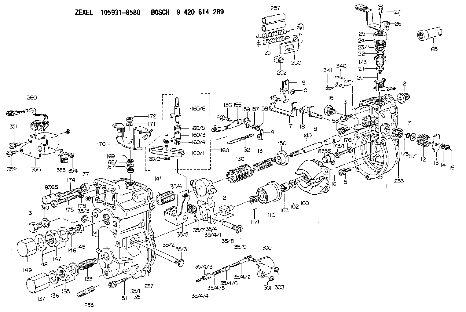
9 420 614 289
9420614289
ZEXEL
105931-8580
1059318580
Rating:
Scheme ###:
| 1. | [1] | 159200-2320 | GOVERNOR HOUSING |
| 1/3. | [2] | 154321-2600 | BUSHING |
| 1/3. | [2] | 154321-2600 | BUSHING |
| 2. | [1] | 154007-0200 | ADAPTOR |
| 3. | [1] | 020018-1840 | BLEEDER SCREW M8P1.25L18 |
| 4. | [1] | 159232-0201 | PLATE |
| 5. | [5] | 029010-6810 | BLEEDER SCREW |
| 5B. | [1] | 020106-1640 | BLEEDER SCREW M6P1.0L14 |
| 7. | [1] | 029631-0030 | O-RING &9.8W2.3 |
| 8. | [1] | 159205-2321 | LEVER SHAFT |
| 9. | [1] | 159202-0400 | CONTROL LEVER |
| 10. | [1] | 016010-0810 | LOCKING WASHER |
| 11/1. | [0] | 029311-0520 | SHIM D20.8&10.3T0.2 |
| 11/1. | [0] | 029311-0530 | SHIM D20.8&10.3T0.25 |
| 11/1. | [0] | 029311-0540 | SHIM D20.8&10.3T0.3 |
| 11/1. | [0] | 029311-0550 | SHIM D20.8&10.3T0.35 |
| 11/1. | [0] | 029311-0560 | SHIM D20.8&10.3T0.4 |
| 11/1. | [0] | 029311-0570 | SHIM D20.8&10.3T0.5 |
| 12. | [1] | 159215-0000 | COILED SPRING |
| 13. | [1] | 159242-0100 | CONTROL LEVER |
| 14. | [1] | 014110-8440 | LOCKING WASHER |
| 15. | [1] | 013020-8040 | UNION NUT M8P1.25H7 |
| 16. | [1] | 159237-0000 | CAPSULE |
| 17. | [1] | 159202-0320 | CONTROL LEVER |
| 18. | [1] | 159215-0300 | COILED SPRING |
| 20. | [1] | 159242-0220 | CONTROL LEVER |
| 21. | [1] | 159242-0600 | BUSHING |
| 22. | [1] | 016530-1010 | O-RING |
| 23/1. | [0] | 029311-0520 | SHIM D20.8&10.3T0.2 |
| 23/1. | [0] | 029311-0530 | SHIM D20.8&10.3T0.25 |
| 23/1. | [0] | 029311-0540 | SHIM D20.8&10.3T0.3 |
| 23/1. | [0] | 029311-0550 | SHIM D20.8&10.3T0.35 |
| 23/1. | [0] | 029311-0560 | SHIM D20.8&10.3T0.4 |
| 23/1. | [0] | 029311-0570 | SHIM D20.8&10.3T0.5 |
| 24. | [1] | 159215-2900 | COILED SPRING |
| 25. | [1] | 154322-0100 | CAP |
| 26. | [1] | 159242-6520 | CONTROL LEVER |
| 27. | [1] | 020006-1640 | BLEEDER SCREW M6P1L16 4T |
| 35. | [1] | 159250-4220 | GOVERNOR COVER |
| 35/1. | [1] | 159301-0920 | GOVERNOR COVER |
| 35/2. | [1] | 159205-0400 | LEVER SHAFT |
| 35/3. | [2] | 159237-0200 | CAPSULE |
| 35/3. | [2] | 159237-0200 | CAPSULE |
| 35/4. | [1] | 159253-2920 | TENSIONING LEVER |
| 35/4/1. | [1] | 159203-0120 | TENSIONING LEVER |
| 35/4/2. | [1] | 159204-5021 | RACK |
| 35/4/3. | [1] | 159233-0300 | UNION NUT |
| 35/4/4. | [1] | 159234-0000 | FLAT-HEAD SCREW |
| 35/4/5. | [1] | 159216-0000 | COILED SPRING |
| 35/4/6. | [1] | 159216-0100 | COILED SPRING |
| 35/5. | [1] | 159203-5020 | GUIDE LEVER |
| 35/6. | [2] | 159235-5000 | BUSHING |
| 35/7. | [1] | 159215-0201 | COILED SPRING |
| 35/8. | [1] | 159231-0800 | BEARING PIN |
| 35/9. | [2] | 016010-0610 | LOCKING WASHER |
| 51. | [7] | 020106-3840 | BLEEDER SCREW |
| 65. | [1] | 154050-1720 | STOPPING DEVICE |
| 100. | [1] | 154100-9520 | FLYWEIGHT ASSEMBLY |
| 101. | [1] | 025803-1610 | WOODRUFF KEY |
| 102. | [1] | 029321-2020 | LOCKING WASHER |
| 103. | [1] | 029231-2030 | UNION NUT |
| 110. | [1] | 154123-1020 | SLIDING PIECE |
| 111/1. | [0] | 029311-0010 | SHIM D14&10.1T0.2 |
| 111/1. | [0] | 029311-0180 | SHIM D14&10.1T0.3 |
| 111/1. | [0] | 029311-0190 | SHIM D14&10.1T0.40 |
| 111/1. | [0] | 029311-0210 | SHIM D14&10.1T1 |
| 111/1. | [0] | 139410-0000 | SHIM D14.0&10.1T0.5 |
| 111/1. | [0] | 139410-0100 | SHIM D14.0&10.1T1.5 |
| 111/1. | [0] | 139410-3000 | SHIM D14&10.1T2.0 |
| 111/1. | [0] | 139410-3100 | SHIM D14&10.1T3.0 |
| 111/1. | [0] | 139410-3200 | SHIM D14&10.1T4.0 |
| 112. | [1] | 159236-0100 | TERMINAL STUD |
| 130. | [1] | 159210-0700 | GOVERNOR SPRING |
| 131. | [1] | 159211-2600 | COILED SPRING |
| 132. | [1] | 159214-0000 | COILED SPRING |
| 133. | [1] | 159212-8320 | HEADLESS SCREW |
| 135. | [1] | 159248-0600 | UNION NUT |
| 136. | [2] | 026520-2440 | GASKET D23.9&20.2T1 |
| 137. | [1] | 159248-0700 | CAP |
| 140. | [1] | 159205-0301 | LEVER SHAFT |
| 141. | [1] | 159234-5200 | GUIDE SLEEVE |
| 145. | [1] | 159233-5000 | UNION NUT |
| 146. | [1] | 023020-8040 | UNION NUT M8P1H5 |
| 147. | [1] | 139222-0200 | UNION NUT |
| 148. | [2] | 026522-2740 | GASKET D26.9&22.2T1 |
| 149. | [1] | 159237-5000 | CAP |
| 150. | [1] | 159235-5300 | SLOTTED WASHER |
| 155. | [1] | 159204-0120 | STRAP |
| 156. | [1] | 159237-0300 | BLEEDER SCREW |
| 157. | [1] | 014110-5440 | LOCKING WASHER |
| 158. | [1] | 159233-5200 | UNION NUT |
| 159. | [1] | 159242-0800 | PLATE |
| 160. | [1] | 159252-2920 | LEVER GROUP |
| 160/1. | [1] | 159202-2200 | CONTROL LEVER |
| 160/2. | [1] | 016010-0810 | LOCKING WASHER |
| 160/3. | [1] | 159202-0220 | CONTROL LEVER |
| 160/4. | [1] | 016010-0810 | LOCKING WASHER |
| 160/5. | [1] | 159215-0400 | COILED SPRING |
| 160/6. | [1] | 159205-0621 | LEVER SHAFT |
| 167. | [1] | 029621-0080 | PACKING RING |
| 168/1. | [0] | 029311-0640 | SHIM D26.0&10.2T0.95 |
| 168/1. | [0] | 029311-0650 | SHIM D26.0&10.2T0.20 |
| 168/1. | [0] | 029311-0660 | SHIM D26.0&10.2T0.25 |
| 168/1. | [0] | 029311-0670 | SHIM D26.0&10.2T0.30 |
| 168/1. | [0] | 029311-0680 | SHIM D26.0&10.2T0.35 |
| 168/1. | [0] | 029311-0690 | SHIM D26.0&10.2T0.40 |
| 168/1. | [0] | 029311-0700 | SHIM D26.0&10.2T0.50 |
| 168/1. | [0] | 139410-1400 | SHIM D26&10.2T0.7 |
| 168/1. | [0] | 139410-1500 | SHIM D26&10.2T0.9 |
| 168/1. | [0] | 139410-1600 | SHIM D26&10.2T0.8 |
| 168/1. | [0] | 139410-2700 | SHIM D26&10.2T0.6 |
| 169. | [1] | 139410-2300 | SHIM |
| 170. | [1] | 159241-5221 | CONTROL LEVER |
| 171. | [1] | 014110-8440 | LOCKING WASHER |
| 172. | [1] | 013020-8040 | UNION NUT M8P1.25H7 |
| 173/1. | [1] | 139006-3500 | BLEEDER SCREW M6P1.0L33 |
| 173/1. | [1] | 139006-3700 | BLEEDER SCREW M6P1.0L34 |
| 173/1. | [1] | 139006-3800 | BLEEDER SCREW M6P1.0L35 |
| 173/1. | [1] | 139006-3900 | BLEEDER SCREW M6P1.0L36 |
| 173/1. | [1] | 139006-5300 | BLEEDER SCREW M6P1.0L31 |
| 173/1. | [1] | 139006-5400 | BLEEDER SCREW M6P1.0L32 |
| 173/1. | [1] | 155615-2500 | BLEEDER SCREW M6P1.0L37 |
| 174. | [1] | 154010-7200 | BLEEDER SCREW M8P1.25L62 |
| 175. | [1] | 154010-2900 | BLEEDER SCREW |
| 176. | [1] | 159225-8600 | UNION NUT |
| 177. | [1] | 154011-2300 | UNION NUT |
| 178. | [1] | 154011-0100 | HEXAGON NUT |
| 236. | [1] | 154390-0000 | GASKET |
| 237. | [1] | 159238-3100 | GASKET |
| 250. | [1] | 159245-8220 | BRACKET |
| 251. | [2] | 159243-3800 | COILED SPRING |
| 252. | [1] | 159248-0200 | BLEEDER SCREW |
| 253. | [1] | 139010-0000 | STUD |
| 257. | [2] | 154156-0700 | TUBE |
| 300. | [1] | 159208-7600 | CAM PLATE |
| 301. | [1] | 016010-0840 | LOCKING WASHER |
| 303. | [1] | 016010-0540 | LOCKING WASHER |
| 310. | [1] | 026516-2040 | GASKET D19.9&16.2T1 |
| 311. | [1] | 159237-0100 | CAPSULE |
| 340. | [1] | 159245-8300 | PLATE |
| 341. | [2] | 020104-1040 | BLEEDER SCREW |
| 350. | [1] | 159225-2600 | BRACKET |
| 351. | [1] | 020118-1440 | BLEEDER SCREW |
| 352. | [2] | 020106-1040 | BLEEDER SCREW M6P1L12 |
| 353. | [1] | 159245-8620 | PLATE |
| 354. | [1] | 020106-0840 | BLEEDER SCREW |
| 360. | [1] | 153169-1320 | MICROSWITCH |
| 835S. | [1] | 154062-1900 | CAP D12L24 |
| 836S. | [1] | 154062-1700 | CAP D20L32 |
Include in #1:
101601-9791
as GOVERNOR
Cross reference number
Zexel num
Bosch num
Firm num
Name
105931-8580
9 420 614 289
GOVERNOR
* K
* K
Information:
Start By:a. remove timing gear cover
Do not disconnect the air line from the air compressor governor until the air pressure is zero.
1. Loosen the bleed valves, and release the air pressure in the air tank. 2. Disconnect the lines from air compressor (1), and remove the air compressor. 3. Remove sleeve (2) from air compressor drive gear (3). 4. Remove the nut and washer that holds the air compressor drive gear to the air compressor. Use tooling (A) to remove air compressor drive gear (3) from the air compressor. 5. Remove nuts (4) and plate (5). Remove gear assembly (6) from the shaft. 6. If damaged, remove bearing (7) from gear assembly (6) with tooling (B) and a press. 7. Remove three nuts (8) and the washers from the adapter assembly studs. 8. Remove adapter assembly (9) from the timing gear plate. 9. Remove shaft (10), O-ring seal (11) and sleeve (12) from the adapter assembly.Install Air Compressor And Accessory Drive
1. Install sleeve (12) into the adapter assembly.2. Install shaft (10) and O-ring seal (11) on the adapter assembly. 3. Put adapter assembly (9) in position on the timing gear plate. fasten it with the three nuts and washers. 4. Install the bearing in gear assembly (6) with tooling (A) and a press. Install the bearing until it is 1.5 0.5 mm (.06 .02 in.) below the surface of the gear as shown. 5. Put gear assembly (6) in position on the shaft.6. Put plate (5) in position, and install three nuts (4) to hold it. 7. Put air compressor drive gear (3) in position on the air compressor shaft, and install the washer and nut (13). Tighten the nut to a torque of 200 25 N m (150 18 lb.ft.). Tap the gear with a hammer and tighten nut again to a torque of 200 25 N m (150 18 lb.ft 8. Install sleeve (2) on gear (3). 9. Put a gasket in position on air compressor (1) and install the air compressor on the timing cover plate.End By:a. install timing gear cover
Have questions with 105931-8580?
Group cross 105931-8580 ZEXEL
Isuzu
105931-8580
9 420 614 289
GOVERNOR