Information governor
BOSCH
9 420 613 052
9420613052
ZEXEL
105931-8511
1059318511

Rating:
Scheme ###:
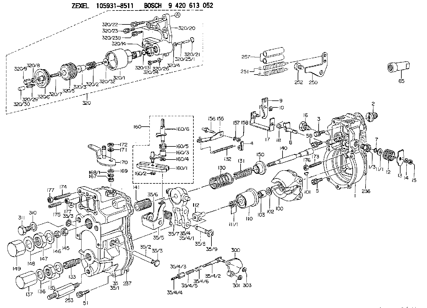
| 1. | [1] | 159200-0620 | GOVERNOR HOUSING |
| 1/3. | [1] | 154321-0400 | BUSHING |
| 2. | [1] | 154007-0200 | ADAPTOR |
| 3. | [1] | 020018-1840 | BLEEDER SCREW M8P1.25L18 |
| 4. | [1] | 159232-0201 | PLATE |
| 5. | [5] | 029010-6810 | BLEEDER SCREW |
| 5B. | [1] | 020106-1640 | BLEEDER SCREW M6P1.0L14 |
| 7. | [1] | 029631-0030 | O-RING &9.8W2.3 |
| 8. | [1] | 159205-2321 | LEVER SHAFT |
| 9. | [1] | 159202-0400 | CONTROL LEVER |
| 10. | [1] | 016010-0810 | LOCKING WASHER |
| 11/1. | [0] | 029311-0520 | SHIM D20.8&10.3T0.2 |
| 11/1. | [0] | 029311-0530 | SHIM D20.8&10.3T0.25 |
| 11/1. | [0] | 029311-0540 | SHIM D20.8&10.3T0.3 |
| 11/1. | [0] | 029311-0550 | SHIM D20.8&10.3T0.35 |
| 11/1. | [0] | 029311-0560 | SHIM D20.8&10.3T0.4 |
| 11/1. | [0] | 029311-0570 | SHIM D20.8&10.3T0.5 |
| 12. | [1] | 159215-0000 | COILED SPRING |
| 13. | [1] | 159242-0100 | CONTROL LEVER |
| 14. | [1] | 014110-8440 | LOCKING WASHER |
| 15. | [1] | 013020-8040 | UNION NUT M8P1.25H7 |
| 16. | [1] | 159237-0000 | CAPSULE |
| 17. | [1] | 159202-0920 | CONTROL LEVER |
| 18. | [1] | 159215-0300 | COILED SPRING |
| 35. | [1] | 159251-3120 | GOVERNOR COVER |
| 35/1. | [1] | 159201-2920 | GOVERNOR COVER |
| 35/2. | [1] | 159205-0400 | LEVER SHAFT |
| 35/3. | [2] | 159237-0200 | CAPSULE |
| 35/3. | [2] | 159237-0200 | CAPSULE |
| 35/4. | [1] | 159253-0120 | TENSIONING LEVER |
| 35/4/1. | [1] | 159203-0120 | TENSIONING LEVER |
| 35/4/2. | [1] | 159204-5021 | RACK |
| 35/4/3. | [1] | 159233-0300 | UNION NUT |
| 35/4/4. | [1] | 159234-0000 | FLAT-HEAD SCREW |
| 35/4/5. | [1] | 159216-0000 | COILED SPRING |
| 35/4/6. | [1] | 159216-0100 | COILED SPRING |
| 35/5. | [1] | 159203-5020 | GUIDE LEVER |
| 35/6. | [2] | 159235-5000 | BUSHING |
| 35/7. | [1] | 159215-0201 | COILED SPRING |
| 35/8. | [1] | 159231-0800 | BEARING PIN |
| 35/9. | [2] | 016010-0610 | LOCKING WASHER |
| 51. | [7] | 020106-3840 | BLEEDER SCREW |
| 65. | [1] | 154050-1720 | STOPPING DEVICE |
| 100. | [1] | 154100-9520 | FLYWEIGHT ASSEMBLY |
| 101. | [1] | 025803-1610 | WOODRUFF KEY |
| 102. | [1] | 029321-2020 | LOCKING WASHER |
| 103. | [1] | 029231-2030 | UNION NUT |
| 110. | [1] | 154123-1020 | SLIDING PIECE |
| 111/1. | [0] | 029311-0010 | SHIM D14&10.1T0.2 |
| 111/1. | [0] | 029311-0180 | SHIM D14&10.1T0.3 |
| 111/1. | [0] | 029311-0190 | SHIM D14&10.1T0.40 |
| 111/1. | [0] | 029311-0210 | SHIM D14&10.1T1 |
| 111/1. | [0] | 139410-0000 | SHIM D14.0&10.1T0.5 |
| 111/1. | [0] | 139410-0100 | SHIM D14.0&10.1T1.5 |
| 111/1. | [0] | 139410-3000 | SHIM D14&10.1T2.0 |
| 111/1. | [0] | 139410-3100 | SHIM D14&10.1T3.0 |
| 111/1. | [0] | 139410-3200 | SHIM D14&10.1T4.0 |
| 112. | [1] | 159236-0100 | TERMINAL STUD |
| 130. | [1] | 159210-0200 | GOVERNOR SPRING |
| 131. | [1] | 159211-0300 | GOVERNOR SPRING |
| 132. | [1] | 159214-0000 | COILED SPRING |
| 133. | [1] | 159212-1020 | HEADLESS SCREW |
| 135. | [1] | 139220-0200 | UNION NUT |
| 136. | [2] | 026520-2440 | GASKET D23.9&20.2T1 |
| 137. | [1] | 159248-0700 | CAP |
| 140. | [1] | 159205-0301 | LEVER SHAFT |
| 141. | [1] | 159234-5200 | GUIDE SLEEVE |
| 145. | [1] | 159233-5000 | UNION NUT |
| 146. | [1] | 023020-8040 | UNION NUT M8P1H5 |
| 147. | [1] | 139222-0200 | UNION NUT |
| 148. | [2] | 026522-2740 | GASKET D26.9&22.2T1 |
| 149. | [1] | 159237-5000 | CAP |
| 150. | [1] | 159235-5300 | SLOTTED WASHER |
| 155. | [1] | 159204-0120 | STRAP |
| 156. | [1] | 159233-0200 | BLEEDER SCREW |
| 157. | [1] | 014110-5440 | LOCKING WASHER |
| 158. | [1] | 159233-5200 | UNION NUT |
| 160. | [1] | 159252-0122 | LEVER GROUP |
| 160/1. | [1] | 159202-2200 | CONTROL LEVER |
| 160/2. | [1] | 016010-0810 | LOCKING WASHER |
| 160/3. | [1] | 159202-0220 | CONTROL LEVER |
| 160/4. | [1] | 016010-0810 | LOCKING WASHER |
| 160/5. | [1] | 159215-0400 | COILED SPRING |
| 160/6. | [1] | 159205-0621 | LEVER SHAFT |
| 167. | [1] | 029621-0080 | PACKING RING |
| 168/1. | [0] | 029311-0640 | SHIM D26.0&10.2T0.95 |
| 168/1. | [0] | 029311-0650 | SHIM D26.0&10.2T0.20 |
| 168/1. | [0] | 029311-0660 | SHIM D26.0&10.2T0.25 |
| 168/1. | [0] | 029311-0670 | SHIM D26.0&10.2T0.30 |
| 168/1. | [0] | 029311-0680 | SHIM D26.0&10.2T0.35 |
| 168/1. | [0] | 029311-0690 | SHIM D26.0&10.2T0.40 |
| 168/1. | [0] | 029311-0700 | SHIM D26.0&10.2T0.50 |
| 168/1. | [0] | 139410-1400 | SHIM D26&10.2T0.7 |
| 168/1. | [0] | 139410-1500 | SHIM D26&10.2T0.9 |
| 168/1. | [0] | 139410-1600 | SHIM D26&10.2T0.8 |
| 168/1. | [0] | 139410-2700 | SHIM D26&10.2T0.6 |
| 169. | [1] | 139410-2300 | SHIM |
| 170. | [1] | 159240-5720 | CONTROL LEVER |
| 171. | [1] | 014110-8440 | LOCKING WASHER |
| 172. | [1] | 013020-8040 | UNION NUT M8P1.25H7 |
| 173. | [1] | 155615-1100 | FLAT-HEAD SCREW M6P1.0L37 |
| 174. | [1] | 154010-0100 | FLAT-HEAD SCREW |
| 175. | [1] | 154010-0100 | FLAT-HEAD SCREW |
| 176. | [1] | 029240-6010 | UNION NUT M6P1.0H5* |
| 177. | [2] | 154011-0100 | HEXAGON NUT |
| 177. | [2] | 154011-0100 | HEXAGON NUT |
| 236. | [1] | 154390-0000 | GASKET |
| 237. | [1] | 159238-3100 | GASKET |
| 250. | [1] | 159245-2820 | BRACKET |
| 251. | [2] | 159243-1900 | COILED SPRING |
| 252. | [1] | 159248-0200 | BLEEDER SCREW |
| 253. | [1] | 159248-0401 | BLEEDER SCREW |
| 257. | [2] | 154156-0500 | TUBE |
| 300. | [1] | 159206-4700 | CAM PLATE |
| 301. | [1] | 016010-0840 | LOCKING WASHER |
| 303. | [1] | 016010-0540 | LOCKING WASHER |
| 310. | [1] | 026516-2040 | GASKET D19.9&16.2T1 |
| 311. | [1] | 159237-0100 | CAPSULE |
| 320. | [1] | 155424-5120 | ANEROID CAPSULE |
| 320/1. | [1] | 155423-7520 | DIAPHRAGM HOUSING |
| 320/2. | [1] | 155423-2900 | COILED SPRING |
| 320/3. | [1] | 155423-1800 | STOP PIN |
| 320/4. | [1] | 016010-0640 | LOCKING WASHER |
| 320/5. | [1] | 155403-3021 | BELLOWS |
| 320/6. | [1] | 155423-2000 | COVER |
| 320/7. | [1] | 155423-1500 | SCREW PLUG |
| 320/8. | [1] | 029240-6010 | UNION NUT M6P1.0H5* |
| 320/9. | [1] | 154035-1600 | CAP NUT |
| 320/13. | [1] | 016520-1510 | O-RING |
| 320/14. | [1] | 139220-0100 | UNION NUT |
| 320/20. | [1] | 155423-1701 | SPACER BUSHING |
| 320/21. | [1] | 159226-4500 | SPACER RING |
| 320/22. | [1] | 020118-3040 | BLEEDER SCREW |
| 320/23. | [3] | 020106-2240 | BLEEDER SCREW |
| 320/23B. | [1] | 020106-2540 | BLEEDER SCREW M6P1L25 |
| 320/24. | [1] | 139006-0900 | BLEEDER SCREW |
| 320/25/1. | [1] | 155423-1200 | STOP PIN L102 |
| 320/25/1. | [1] | 155424-4900 | STOP PIN L95 |
| 320/25/1. | [1] | 155424-5000 | STOP PIN L96 |
| 320/25/1B. | [1] | 155423-1300 | STOP PIN L102.5 |
| 320/25/1C. | [1] | 155423-1400 | STOP PIN L103 |
| 320/25/1D. | [1] | 155423-7600 | STOP PIN L103.5 |
| 320/25/1E. | [1] | 155423-7700 | STOP PIN L104 |
| 320/25/1F. | [1] | 155423-8700 | STOP PIN L97 |
| 320/25/1G. | [1] | 155423-8800 | STOP PIN L98 |
| 320/25/1H. | [1] | 155423-8900 | STOP PIN L99 |
| 320/25/1I. | [1] | 155423-9000 | STOP PIN L100 |
| 320/25/1J. | [1] | 155423-9100 | STOP PIN L101 |
| 320/26. | [1] | 014110-6440 | LOCKING WASHER |
| 320/29. | [1] | 139805-0000 | JOINT CONNECTION |
| 320/30. | [1] | 155424-0300 | CAP |
| 320/32. | [1] | 029311-2060 | SHIM D22&12.5T0.5 |
Include in #1:
101401-4140
as GOVERNOR
Cross reference number
Zexel num
Bosch num
Firm num
Name
Information:
1. With the rear of wire connector toward you, snap tool (A) (the correct size for the wire being removed) over the wire of the contact to be removed.2. Slide tool (A) along the wire into the contact cavity until it engages the contact and resistance is felt. Do not twist or insert tool (A) at an angle. 3. Pull contact (2) and wire assembly out of connector (1).4. Remove the damaged contact from the wire. 5. Use tool (B) and the following procedure to secure contact (2) to the wire.a. Strip 6.3 mm (.25 in.) insulation from the wire.b. Raise selector knob (3) and rotate until arrow is aligned with the wire size to be crimped.c. Loosen locknut. Turn adjusting screw (4) in (clockwise) until it stops. d. Insert contact (2) into tool (B). Turn the adjusting screw out (counter clockwise) until the contact is flush with indentor cover (5) on tool (B). Tighten locknut. c. Insert wire in contact (2). The contact must be centered between the indentors. Close the handles until the handle contacts the stop.d. Release the handles and remove the crimped contact.e. Inspect the contact to insure that all wire strands are inside the crimp barrel. Look in the hole in the contact. If the crimp is correct wire strands will be visible in the hole in the contact. 6. Grasp the wire approximately 25.4 mm (1.00 in.) behind the contact crimp barrel.7. Hold connector (1) with the rear grommet facing you.8. Push contact (2) straight into connector (1) until a positive stop is felt.9. Gently pull on the wire and connector assembly to confirm that the contact is properly locked in place.