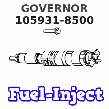
Information governor
BOSCH
F 019 Z1F 052
f019z1f052
ZEXEL
105931-8500
1059318500
Rating:
Scheme ###:
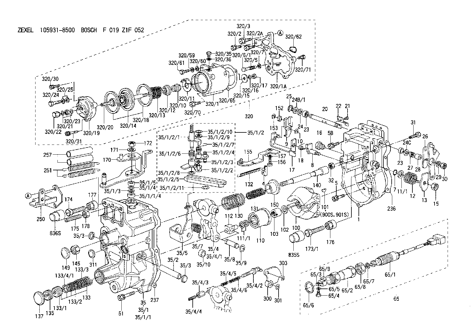
| 1. | [1] | 159200-7620 | GOVERNOR HOUSING |
| 4. | [1] | 159232-0201 | PLATE |
| 5. | [8] | 139006-4100 | BLEEDER SCREW |
| 5B. | [2] | 139006-6000 | BLEEDER SCREW |
| 7. | [1] | 016530-1010 | O-RING |
| 8. | [1] | 159205-2321 | LEVER SHAFT |
| 9. | [1] | 159202-2301 | CONTROL LEVER |
| 10. | [1] | 016010-0810 | LOCKING WASHER |
| 11/1. | [0] | 029311-0220 | SHIM D18&10.3T0.2 |
| 11/1. | [0] | 029311-0230 | SHIM D18&10.3T0.5 |
| 11/1. | [0] | 029311-0430 | SHIM D18&10.3T0.30 |
| 11/1. | [0] | 029311-0440 | SHIM D18&10.3T0.40 |
| 11/1. | [0] | 029311-0450 | SHIM D18&10.3T0.25 |
| 11/1. | [0] | 029311-0460 | SHIM D18&10.3T0.35 |
| 11/1. | [0] | 139410-3300 | SHIM D18&10.3T0.6 |
| 11/1. | [0] | 139410-3400 | SHIM D18&10.3T0.8 |
| 11/1. | [0] | 139410-3500 | SHIM D18&10.3T0.9 |
| 12. | [1] | 159215-0000 | COILED SPRING |
| 13. | [1] | 159242-6601 | CONTROL LEVER |
| 15. | [1] | 013020-8040 | UNION NUT M8P1.25H7 |
| 16. | [1] | 159237-5500 | CAPSULE |
| 17. | [1] | 159202-5220 | CONTROL LEVER |
| 18. | [1] | 159215-0300 | COILED SPRING |
| 20. | [1] | 155004-5100 | LEVER SHAFT |
| 21. | [2] | 020104-1240 | BLEEDER SCREW |
| 22. | [1] | 159290-4000 | CONTROL LEVER |
| 23. | [2] | 139608-0400 | PACKING RING |
| 23. | [2] | 139608-0400 | PACKING RING |
| 24. | [1] | 139308-1400 | PLAIN WASHER |
| 24B/1. | [0] | 139408-1000 | SHIM D16&8T0.5 |
| 24B/1. | [0] | 139408-1300 | SHIM D16&8T0.2 |
| 24C. | [1] | 139308-1400 | PLAIN WASHER |
| 25. | [1] | 159238-4200 | LOCKING WASHER |
| 26. | [1] | 159290-7200 | CONTROL LEVER |
| 27. | [1] | 159215-5300 | COILED SPRING |
| 28. | [1] | 159230-3400 | BUSHING |
| 29. | [1] | 014110-8440 | LOCKING WASHER |
| 30. | [1] | 013020-8040 | UNION NUT M8P1.25H7 |
| 31. | [1] | 155644-1301 | BLEEDER SCREW |
| 32. | [1] | 013030-6040 | UNION NUT M6P1H3.6 |
| 35. | [1] | 159250-5720 | GOVERNOR COVER |
| 35/1. | [1] | 159301-2620 | GOVERNOR COVER |
| 35/1/1. | [1] | 159301-2520 | GOVERNOR COVER |
| 35/1/1/4. | [1] | 159230-2800 | BUSHING |
| 35/1/2. | [1] | 159252-3320 | LEVER GROUP |
| 35/1/2/1. | [1] | 159205-5420 | LEVER SHAFT |
| 35/1/2/2. | [1] | 159202-4810 | CONTROL LEVER |
| 35/1/2/3. | [1] | 029310-6030 | SHIM D11.5&6.2T0.2 |
| 35/1/2/4. | [1] | 159202-4520 | CONTROL LEVER |
| 35/1/2/5. | [1] | 159202-2200 | CONTROL LEVER |
| 35/1/2/6. | [1] | 159215-2301 | COILED SPRING |
| 35/1/2/7. | [1] | 159215-3900 | COILED SPRING |
| 35/1/2/8. | [1] | 016010-0810 | LOCKING WASHER |
| 35/1/2/9. | [1] | 014020-6140 | PLAIN WASHER |
| 35/1/2/10. | [1] | 016010-0610 | LOCKING WASHER |
| 35/1/2/11. | [1] | 016010-0810 | LOCKING WASHER |
| 35/1/3. | [1] | 139411-0600 | SHIM |
| 35/1/4. | [1] | 159238-3000 | LOCKING WASHER |
| 35/1/5. | [1] | 029621-0080 | PACKING RING |
| 35/2. | [1] | 159205-0400 | LEVER SHAFT |
| 35/3. | [2] | 159237-0200 | CAPSULE |
| 35/3. | [2] | 159237-0200 | CAPSULE |
| 35/4. | [1] | 159253-2220 | TENSIONING LEVER |
| 35/4/1. | [1] | 159203-1720 | TENSIONING LEVER |
| 35/4/2. | [1] | 159204-5021 | RACK |
| 35/4/3. | [1] | 159233-0300 | UNION NUT |
| 35/4/4. | [1] | 159234-0300 | FLAT-HEAD SCREW |
| 35/4/5. | [1] | 159216-0000 | COILED SPRING |
| 35/4/6. | [1] | 159216-0100 | COILED SPRING |
| 35/5. | [1] | 159203-6420 | GUIDE LEVER |
| 35/7. | [1] | 159215-4101 | COILED SPRING |
| 35/8. | [1] | 159231-1300 | BEARING PIN |
| 35/9. | [2] | 016010-0610 | LOCKING WASHER |
| 35/10. | [1] | 159238-2900 | BUSHING |
| 51. | [7] | 020106-3840 | BLEEDER SCREW |
| 65. | [1] | 154610-4220 | RACK SENSOR ASSY |
| 65/1. | [1] | 479742-0420 | RACK SENSOR |
| 65/2. | [1] | 154614-4800 | JOINT CONNECTION |
| 65/3. | [1] | 154614-5300 | BLOCK |
| 65/4. | [1] | 010234-1040 | HEX-SOCKET-HEAD CAP SCREW |
| 65/5. | [1] | 014110-4440 | LOCKING WASHER |
| 65/6. | [1] | 026524-3040 | GASKET |
| 65/7. | [1] | 029310-6280 | SHIM D11.5&6.4T1.50 |
| 65/8. | [1] | 154614-1900 | UNION NUT |
| 65/9. | [1] | 154614-3300 | BEARING PIN |
| 100. | [1] | 154100-9520 | FLYWEIGHT ASSEMBLY |
| 101. | [1] | 025803-1310 | WOODRUFF KEY |
| 102. | [1] | 029321-2020 | LOCKING WASHER |
| 103. | [1] | 029231-2030 | UNION NUT |
| 110. | [1] | 154123-2320 | SLIDING PIECE |
| 111/1. | [0] | 029311-0010 | SHIM D14&10.1T0.2 |
| 111/1. | [0] | 029311-0180 | SHIM D14&10.1T0.3 |
| 111/1. | [0] | 029311-0190 | SHIM D14&10.1T0.40 |
| 111/1. | [0] | 029311-0210 | SHIM D14&10.1T1 |
| 111/1. | [0] | 139410-0000 | SHIM D14.0&10.1T0.5 |
| 111/1. | [0] | 139410-0100 | SHIM D14.0&10.1T1.5 |
| 111/1. | [0] | 139410-3000 | SHIM D14&10.1T2.0 |
| 111/1. | [0] | 139410-3100 | SHIM D14&10.1T3.0 |
| 111/1. | [0] | 139410-3200 | SHIM D14&10.1T4.0 |
| 112. | [1] | 159236-0200 | TERMINAL STUD |
| 130. | [1] | 159210-3200 | GOVERNOR SPRING |
| 131. | [1] | 159211-1600 | GOVERNOR SPRING |
| 132. | [1] | 159214-0000 | COILED SPRING |
| 133. | [1] | 159212-7120 | SPRING PACK |
| 133/1. | [1] | 159234-5602 | GUIDE SLEEVE |
| 133/2. | [1] | 159212-5500 | COILED SPRING |
| 133/3. | [1] | 159212-3400 | COILED SPRING |
| 133/4/1. | [0] | 029310-9240 | SHIM D11.9&9T0.1 |
| 133/4/1. | [0] | 029310-9250 | SHIM D11.9&9T0.2 |
| 133/4/1. | [0] | 029310-9260 | SHIM D11.9&9T0.25 |
| 133/4/1. | [0] | 029310-9270 | SHIM D11.9&9T1.0 |
| 133/4/1. | [0] | 139409-0100 | SHIM D11.9&9T0.3 |
| 133/4/1. | [0] | 139409-0200 | SHIM D11.9&9T0.5 |
| 133/4/1. | [0] | 139409-0300 | SHIM D11.5&9T0.8 |
| 135. | [1] | 159248-2700 | FLAT-HEAD SCREW |
| 137. | [1] | 159237-5300 | CAPSULE |
| 140. | [1] | 159205-2101 | LEVER SHAFT |
| 145. | [1] | 159233-5700 | UNION NUT |
| 149. | [1] | 159237-5400 | CAPSULE |
| 150. | [1] | 159235-5300 | SLOTTED WASHER |
| 152. | [1] | 159235-5200 | BUSHING |
| 153. | [1] | 016010-0540 | LOCKING WASHER |
| 155. | [1] | 159204-6820 | STRAP |
| 156. | [1] | 010235-1020 | HEX-SOCKET-HEAD CAP SCREW |
| 157. | [1] | 029320-5020 | LOCKING WASHER |
| 170. | [1] | 159265-1020 | CONTROL LEVER |
| 171. | [1] | 014110-8440 | LOCKING WASHER |
| 172. | [1] | 013020-8040 | UNION NUT M8P1.25H7 |
| 173/1. | [1] | 139006-3500 | BLEEDER SCREW M6P1.0L33 |
| 173/1. | [1] | 139006-3700 | BLEEDER SCREW M6P1.0L34 |
| 173/1. | [1] | 139006-3800 | BLEEDER SCREW M6P1.0L35 |
| 173/1. | [1] | 139006-3900 | BLEEDER SCREW M6P1.0L36 |
| 173/1. | [1] | 139006-5300 | BLEEDER SCREW M6P1.0L31 |
| 173/1. | [1] | 139006-5400 | BLEEDER SCREW M6P1.0L32 |
| 173/1. | [1] | 155615-2500 | BLEEDER SCREW M6P1.0L37 |
| 174. | [1] | 154010-7200 | BLEEDER SCREW M8P1.25L62 |
| 175. | [1] | 154010-0100 | FLAT-HEAD SCREW |
| 176. | [1] | 159225-8600 | UNION NUT |
| 177. | [1] | 154011-2300 | UNION NUT |
| 178. | [1] | 154011-0100 | HEXAGON NUT |
| 236. | [1] | 159238-4000 | GASKET |
| 237. | [1] | 159238-3100 | GASKET |
| 250. | [1] | 159220-5021 | BRACKET |
| 251. | [2] | 154332-3600 | COILED SPRING |
| 257. | [2] | 154156-1800 | TUBE |
| 300. | [1] | 159283-2100 | CAM PLATE |
| 301. | [1] | 016010-0840 | LOCKING WASHER |
| 303. | [1] | 016010-0540 | LOCKING WASHER |
| 311. | [1] | 159237-0200 | CAPSULE |
| 320. | [1] | 154419-9120 | MANIFOLD-PRESSURE COMP. |
| 320/1. | [1] | 154413-6420 | DIAPHRAGM HOUSING |
| 320/1A. | [1] | 154413-6500 | SPACER BUSHING |
| 320/2. | [1] | 020106-2240 | BLEEDER SCREW |
| 320/2A. | [2] | 020106-2540 | BLEEDER SCREW M6P1L25 |
| 320/3. | [1] | 020118-3040 | BLEEDER SCREW |
| 320/5. | [1] | 159275-1400 | COILED SPRING |
| 320/6/1. | [1] | 159274-0120 | STOP PIN L125 |
| 320/6/1. | [1] | 159274-0220 | STOP PIN L127.50 |
| 320/6/1. | [1] | 159274-0320 | STOP PIN L128.00 |
| 320/6/1. | [1] | 159274-0420 | STOP PIN L127.00 |
| 320/6/1. | [1] | 159274-0520 | STOP PIN L126.00 |
| 320/6/1. | [1] | 159274-0620 | STOP PIN L129.00 |
| 320/6/1. | [1] | 159274-0720 | STOP PIN L128.50 |
| 320/6/1. | [1] | 159274-0820 | STOP PIN L125.50 |
| 320/6/1. | [1] | 159274-0920 | STOP PIN L126.50 |
| 320/6/1. | [1] | 159274-1120 | STOP PIN L119.5 |
| 320/6/1. | [1] | 159274-1220 | STOP PIN L120 |
| 320/6/1. | [1] | 159274-1320 | STOP PIN L120.5 |
| 320/6/1. | [1] | 159274-1420 | STOP PIN L121 |
| 320/6/1. | [1] | 159274-1520 | STOP PIN L121.5 |
| 320/6/1. | [1] | 159274-1620 | STOP PIN L122 |
| 320/6/1. | [1] | 159274-1720 | STOP PIN L122.5 |
| 320/6/1. | [1] | 159274-1820 | STOP PIN L123 |
| 320/6/1. | [1] | 159274-1920 | STOP PIN L123.5 |
| 320/6/1. | [1] | 159274-4220 | STOP PIN L129.5 |
| 320/6/1. | [1] | 159274-4320 | STOP PIN L130 |
| 320/6/1. | [1] | 159274-4420 | STOP PIN L130.5 |
| 320/6/1. | [1] | 159274-4520 | STOP PIN L131 |
| 320/6/1. | [1] | 159274-4620 | STOP PIN L131.5 |
| 320/6/1. | [1] | 159274-4720 | STOP PIN L132 |
| 320/6/1. | [1] | 159274-4820 | STOP PIN L132.5 |
| 320/6/1. | [1] | 159274-4920 | STOP PIN L133 |
| 320/6/1. | [1] | 159274-5020 | STOP PIN L133.5 |
| 320/7. | [1] | 014010-5140 | PLAIN WASHER D12&5.5T0.8 |
| 320/10. | [1] | 154413-3600 | BUSHING |
| 320/11. | [1] | 146711-0000 | PLATE |
| 320/12. | [1] | 146716-0000 | UNION NUT |
| 320/13. | [1] | 154403-3800 | COILED SPRING |
| 320/14. | [1] | 154415-4320 | DIAPHRAGM |
| 320/15. | [1] | 154406-5500 | SLOTTED WASHER |
| 320/16. | [1] | 014110-6440 | LOCKING WASHER |
| 320/17. | [1] | 013030-6040 | UNION NUT M6P1H3.6 |
| 320/18. | [2] | 154413-2600 | GASKET |
| 320/19. | [1] | 154404-5000 | COVER |
| 320/20. | [1] | 154413-4000 | FLAT-HEAD SCREW |
| 320/21. | [1] | 013030-6040 | UNION NUT M6P1H3.6 |
| 320/22. | [1] | 154035-1600 | CAP NUT |
| 320/23. | [2] | 139506-0300 | GASKET |
| 320/24. | [1] | 029731-0180 | EYE BOLT |
| 320/25. | [2] | 139510-0200 | GASKET |
| 320/30. | [1] | 020106-3040 | BLEEDER SCREW |
| 320/31. | [2] | 029010-6540 | BLEEDER SCREW |
| 320/35. | [1] | 029111-2090 | CAPSULE |
| 320/36. | [1] | 139512-0000 | GASKET D17.2&12.2T1.0 |
| 320/59. | [1] | 014010-6140 | PLAIN WASHER D13&6.5T1 |
| 320/60. | [1] | 139505-0000 | PLAIN WASHER |
| 320/61. | [1] | 010006-1670 | BLEEDER SCREW M6P1L16 7T |
| 320/62. | [1] | 159226-4500 | SPACER RING |
| 320/65. | [1] | 154390-1900 | GASKET |
| 320/70. | [2] | 020106-2040 | BLEEDER SCREW M6P1L20 |
| 320/71. | [3] | 020106-2240 | BLEEDER SCREW |
| 835S. | [1] | 154062-1900 | CAP D12L24 |
| 836S. | [1] | 154062-1700 | CAP D20L32 |
| 900S. | [1] | 025803-1310 | WOODRUFF KEY |
| 901S. | [1] | 025803-1610 | WOODRUFF KEY |
Include in #1:
107692-1080
as GOVERNOR
Cross reference number
Zexel num
Bosch num
Firm num
Name
105931-8500
F 019 Z1F 052
GOVERNOR
* K
* K
Information:
1. Disconnect fuel line (1) from the fuel transfer pump. Disconnect fuel line (2) from the fuel injection pump housing. Remove line (3) from the transducer module and aftercooler housing.2. Disconnect fuel injection lines (4) from the fuel injection pump housing.
Do not disconnect the air line from the air compressor until the air pressure is zero.
3. Loosen the bleed valves, and release the air pressure in the air tank.4. Remove air line (5). Remove coolant line (6). 5. Disconnect wiring harness from bracket (7). Disconnect wires at connectors (8).
Typical Example6. The weight of the fuel injection pump housing and rack actuator package is approximately 57Kg (125 lb.). Attach a hoist to the fuel injection pump housing and remove bolts (9).
Typical Example7. Remove two nuts (on shown) and two bolts (10). Remove bolt (11). Remove the fuel injection pump housing and rack actuator package (12).
Typical Example8. Remove O-ring seals (13) from the fuel injection pump housing.Install Fuel Injection Pump Housing And Rack Actuator Package
1. Attach a hoist to the fuel injection pump housing and rack actuator package (12). Be sure that the three O-ring seals are in position in the fuel injection pump housing. Install the fuel injection pump housing and rack actuator package on the timing gear housing. 2. Connect the wires at connectors (8).
Transducer Module3. Connect P5 to J5 connector, J11 to P11 connector, and P10 to J10 connector. 4. Install air line (5) and coolant line (6).5. Connect fuel injection lines (4) to the fuel injection pump housing. Tighten the fuel injection line nut to a torque of 40 7 N*m (30 5 lb.ft.) with tool (A).6. Connect the fuel line (1) to the fuel transfer pump. Connect fuel line (2) to the fuel injection pump housing. Install line (3) to the transducer module and aftercooler housing. For timing of the fuel injection pump, see Install Timing Advance Unit.End By:a. install timing advance unit
Have questions with 105931-8500?
Group cross 105931-8500 ZEXEL
105931-8500
F 019 Z1F 052
GOVERNOR