Information governor
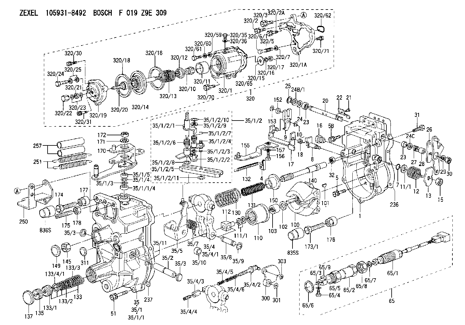
BOSCH
F 019 Z9E 309
f019z9e309
ZEXEL
105931-8492
1059318492
Rating:
Scheme ###:
| 1. | [1] | 159200-7620 | GOVERNOR HOUSING |
| 4. | [1] | 159232-0201 | PLATE |
| 5. | [8] | 139006-4100 | BLEEDER SCREW |
| 5B. | [2] | 139006-6000 | BLEEDER SCREW |
| 7. | [1] | 016530-1010 | O-RING |
| 8. | [1] | 159205-2321 | LEVER SHAFT |
| 9. | [1] | 159202-2301 | CONTROL LEVER |
| 10. | [1] | 016010-0810 | LOCKING WASHER |
| 11/1. | [0] | 029311-0220 | SHIM D18&10.3T0.2 |
| 11/1. | [0] | 029311-0230 | SHIM D18&10.3T0.5 |
| 11/1. | [0] | 029311-0430 | SHIM D18&10.3T0.30 |
| 11/1. | [0] | 029311-0440 | SHIM D18&10.3T0.40 |
| 11/1. | [0] | 029311-0450 | SHIM D18&10.3T0.25 |
| 11/1. | [0] | 029311-0460 | SHIM D18&10.3T0.35 |
| 11/1. | [0] | 139410-3300 | SHIM D18&10.3T0.6 |
| 11/1. | [0] | 139410-3400 | SHIM D18&10.3T0.8 |
| 11/1. | [0] | 139410-3500 | SHIM D18&10.3T0.9 |
| 12. | [1] | 159215-0000 | COILED SPRING |
| 13. | [1] | 159242-6601 | CONTROL LEVER |
| 15. | [1] | 013020-8040 | UNION NUT M8P1.25H7 |
| 16. | [1] | 159237-5500 | CAPSULE |
| 17. | [1] | 159202-5220 | CONTROL LEVER |
| 18. | [1] | 159215-0300 | COILED SPRING |
| 20. | [1] | 155004-5100 | LEVER SHAFT |
| 21. | [2] | 012154-1040 | FLAT-HEAD SCREW M4P0.7L10 |
| 22. | [1] | 159290-4000 | CONTROL LEVER |
| 23. | [2] | 139608-0400 | PACKING RING |
| 23. | [2] | 139608-0400 | PACKING RING |
| 24. | [1] | 139308-1900 | PLAIN WASHER |
| 24B/1. | [0] | 139408-1000 | SHIM D16&8T0.5 |
| 24B/1. | [0] | 139408-1300 | SHIM D16&8T0.2 |
| 24C. | [1] | 139308-1900 | PLAIN WASHER |
| 25. | [1] | 159238-4200 | LOCKING WASHER |
| 26. | [1] | 159290-7421 | CONTROL LEVER |
| 27. | [1] | 159215-5300 | COILED SPRING |
| 28. | [1] | 159230-3400 | BUSHING |
| 29. | [1] | 014110-8440 | LOCKING WASHER |
| 30. | [1] | 013020-8040 | UNION NUT M8P1.25H7 |
| 31. | [1] | 155644-1301 | BLEEDER SCREW |
| 32. | [1] | 013030-6040 | UNION NUT M6P1H3.6 |
| 35. | [1] | 159250-6420 | GOVERNOR COVER |
| 35/1. | [1] | 159301-2620 | GOVERNOR COVER |
| 35/1/1. | [1] | 159301-2520 | GOVERNOR COVER |
| 35/1/1/4. | [1] | 159230-2800 | BUSHING |
| 35/1/2. | [1] | 159252-3320 | LEVER GROUP |
| 35/1/2/1. | [1] | 159205-5420 | LEVER SHAFT |
| 35/1/2/2. | [1] | 159202-4810 | CONTROL LEVER |
| 35/1/2/3. | [1] | 029310-6030 | SHIM D11.5&6.2T0.2 |
| 35/1/2/4. | [1] | 159202-4520 | CONTROL LEVER |
| 35/1/2/5. | [1] | 159202-2200 | CONTROL LEVER |
| 35/1/2/6. | [1] | 159215-2301 | COILED SPRING |
| 35/1/2/7. | [1] | 159215-3900 | COILED SPRING |
| 35/1/2/8. | [1] | 016010-0810 | LOCKING WASHER |
| 35/1/2/9. | [1] | 014020-6140 | PLAIN WASHER |
| 35/1/2/10. | [1] | 016010-0610 | LOCKING WASHER |
| 35/1/2/11. | [1] | 016010-0810 | LOCKING WASHER |
| 35/1/3. | [1] | 139411-0600 | SHIM |
| 35/1/4. | [1] | 159238-3000 | LOCKING WASHER |
| 35/1/5. | [1] | 029621-0080 | PACKING RING |
| 35/2. | [1] | 159205-5500 | LEVER SHAFT |
| 35/3. | [2] | 159237-0200 | CAPSULE |
| 35/3. | [2] | 159237-0200 | CAPSULE |
| 35/4. | [1] | 159253-2220 | TENSIONING LEVER |
| 35/4/1. | [1] | 159203-1720 | TENSIONING LEVER |
| 35/4/2. | [1] | 159204-5021 | RACK |
| 35/4/3. | [1] | 159233-0300 | UNION NUT |
| 35/4/4. | [1] | 159234-0300 | FLAT-HEAD SCREW |
| 35/4/5. | [1] | 159216-0000 | COILED SPRING |
| 35/4/6. | [1] | 159216-0100 | COILED SPRING |
| 35/5. | [1] | 159203-6420 | GUIDE LEVER |
| 35/7. | [1] | 159215-5400 | COILED SPRING |
| 35/8. | [1] | 159231-1300 | BEARING PIN |
| 35/9. | [2] | 016010-0610 | LOCKING WASHER |
| 35/10. | [1] | 159238-4100 | BUSHING |
| 35/11. | [1] | 016010-1010 | LOCKING WASHER |
| 51. | [7] | 020106-3840 | BLEEDER SCREW |
| 65. | [1] | 154610-4620 | RACK SENSOR ASSY |
| 65/1. | [1] | 479742-2120 | RACK SENSOR |
| 65/2. | [1] | 154614-4800 | JOINT CONNECTION |
| 65/3. | [1] | 154614-5300 | BLOCK |
| 65/4. | [1] | 010234-1040 | HEX-SOCKET-HEAD CAP SCREW |
| 65/5. | [1] | 014110-4440 | LOCKING WASHER |
| 65/6. | [1] | 026524-3040 | GASKET |
| 65/7. | [1] | 029310-6280 | SHIM D11.5&6.4T1.50 |
| 65/8. | [1] | 154614-1900 | UNION NUT |
| 65/9. | [1] | 154614-3300 | BEARING PIN |
| 100. | [1] | 154100-9520 | FLYWEIGHT ASSEMBLY |
| 101. | [1] | 025803-1610 | WOODRUFF KEY |
| 102. | [1] | 029321-2020 | LOCKING WASHER |
| 103. | [1] | 029231-2030 | UNION NUT |
| 110. | [1] | 154123-2320 | SLIDING PIECE |
| 111/1. | [0] | 029311-0010 | SHIM D14&10.1T0.2 |
| 111/1. | [0] | 029311-0180 | SHIM D14&10.1T0.3 |
| 111/1. | [0] | 029311-0190 | SHIM D14&10.1T0.40 |
| 111/1. | [0] | 029311-0210 | SHIM D14&10.1T1 |
| 111/1. | [0] | 139410-0000 | SHIM D14.0&10.1T0.5 |
| 111/1. | [0] | 139410-0100 | SHIM D14.0&10.1T1.5 |
| 111/1. | [0] | 139410-3000 | SHIM D14&10.1T2.0 |
| 111/1. | [0] | 139410-3100 | SHIM D14&10.1T3.0 |
| 111/1. | [0] | 139410-3200 | SHIM D14&10.1T4.0 |
| 112. | [1] | 159236-0200 | TERMINAL STUD |
| 130. | [1] | 159210-3200 | GOVERNOR SPRING |
| 131. | [1] | 159211-1600 | GOVERNOR SPRING |
| 132. | [1] | 159214-0000 | COILED SPRING |
| 133. | [1] | 159212-7120 | SPRING PACK |
| 133/1. | [1] | 159234-5602 | GUIDE SLEEVE |
| 133/2. | [1] | 159212-5500 | COILED SPRING |
| 133/3. | [1] | 159212-3400 | COILED SPRING |
| 133/4/1. | [0] | 029310-9240 | SHIM D11.9&9T0.1 |
| 133/4/1. | [0] | 029310-9250 | SHIM D11.9&9T0.2 |
| 133/4/1. | [0] | 029310-9260 | SHIM D11.9&9T0.25 |
| 133/4/1. | [0] | 029310-9270 | SHIM D11.9&9T1.0 |
| 133/4/1. | [0] | 139409-0100 | SHIM D11.9&9T0.3 |
| 133/4/1. | [0] | 139409-0200 | SHIM D11.9&9T0.5 |
| 133/4/1. | [0] | 139409-0300 | SHIM D11.5&9T0.8 |
| 135. | [1] | 159248-2700 | FLAT-HEAD SCREW |
| 137. | [1] | 159237-5300 | CAPSULE |
| 140. | [1] | 159205-2101 | LEVER SHAFT |
| 145. | [1] | 159233-5700 | UNION NUT |
| 149. | [1] | 159237-5400 | CAPSULE |
| 150. | [1] | 159235-5300 | SLOTTED WASHER |
| 152. | [1] | 159235-5200 | BUSHING |
| 153. | [1] | 016010-0540 | LOCKING WASHER |
| 155. | [1] | 159204-6820 | STRAP |
| 156. | [1] | 010235-1020 | HEX-SOCKET-HEAD CAP SCREW |
| 157. | [1] | 029320-5020 | LOCKING WASHER |
| 170. | [1] | 159265-3420 | CONTROL LEVER |
| 171. | [1] | 014110-8440 | LOCKING WASHER |
| 172. | [1] | 013020-8040 | UNION NUT M8P1.25H7 |
| 173/1. | [1] | 139006-3500 | BLEEDER SCREW M6P1.0L33 |
| 173/1. | [1] | 139006-3700 | BLEEDER SCREW M6P1.0L34 |
| 173/1. | [1] | 139006-3800 | BLEEDER SCREW M6P1.0L35 |
| 173/1. | [1] | 139006-3900 | BLEEDER SCREW M6P1.0L36 |
| 173/1. | [1] | 139006-5300 | BLEEDER SCREW M6P1.0L31 |
| 173/1. | [1] | 139006-5400 | BLEEDER SCREW M6P1.0L32 |
| 173/1. | [1] | 155615-2500 | BLEEDER SCREW M6P1.0L37 |
| 174. | [1] | 154010-7200 | BLEEDER SCREW M8P1.25L62 |
| 175. | [1] | 154010-0100 | FLAT-HEAD SCREW |
| 176. | [1] | 159225-8600 | UNION NUT |
| 177. | [1] | 154011-2300 | UNION NUT |
| 178. | [1] | 154011-0100 | HEXAGON NUT |
| 236. | [1] | 159238-4000 | GASKET |
| 237. | [1] | 159238-3100 | GASKET |
| 250. | [1] | 159220-6221 | BRACKET |
| 251. | [2] | 154332-4600 | COILED SPRING |
| 257. | [2] | 154156-2300 | TUBE |
| 300. | [1] | 159283-4800 | CAM PLATE |
| 301. | [1] | 016010-0840 | LOCKING WASHER |
| 303. | [1] | 016010-0540 | LOCKING WASHER |
| 311. | [1] | 159237-0200 | CAPSULE |
| 320. | [1] | 154419-9120 | MANIFOLD-PRESSURE COMP. |
| 320/1. | [1] | 154413-6420 | DIAPHRAGM HOUSING |
| 320/1A. | [1] | 154413-6500 | SPACER BUSHING |
| 320/2. | [1] | 020106-2240 | BLEEDER SCREW |
| 320/2A. | [2] | 020106-2540 | BLEEDER SCREW M6P1L25 |
| 320/3. | [1] | 020118-3040 | BLEEDER SCREW |
| 320/5. | [1] | 159275-1400 | COILED SPRING |
| 320/6/1. | [1] | 159274-0120 | STOP PIN L125 |
| 320/6/1. | [1] | 159274-0220 | STOP PIN L127.50 |
| 320/6/1. | [1] | 159274-0320 | STOP PIN L128.00 |
| 320/6/1. | [1] | 159274-0420 | STOP PIN L127.00 |
| 320/6/1. | [1] | 159274-0520 | STOP PIN L126.00 |
| 320/6/1. | [1] | 159274-0620 | STOP PIN L129.00 |
| 320/6/1. | [1] | 159274-0720 | STOP PIN L128.50 |
| 320/6/1. | [1] | 159274-0820 | STOP PIN L125.50 |
| 320/6/1. | [1] | 159274-0920 | STOP PIN L126.50 |
| 320/6/1. | [1] | 159274-1120 | STOP PIN L119.5 |
| 320/6/1. | [1] | 159274-1220 | STOP PIN L120 |
| 320/6/1. | [1] | 159274-1320 | STOP PIN L120.5 |
| 320/6/1. | [1] | 159274-1420 | STOP PIN L121 |
| 320/6/1. | [1] | 159274-1520 | STOP PIN L121.5 |
| 320/6/1. | [1] | 159274-1620 | STOP PIN L122 |
| 320/6/1. | [1] | 159274-1720 | STOP PIN L122.5 |
| 320/6/1. | [1] | 159274-1820 | STOP PIN L123 |
| 320/6/1. | [1] | 159274-1920 | STOP PIN L123.5 |
| 320/6/1. | [1] | 159274-4220 | STOP PIN L129.5 |
| 320/6/1. | [1] | 159274-4320 | STOP PIN L130 |
| 320/6/1. | [1] | 159274-4420 | STOP PIN L130.5 |
| 320/6/1. | [1] | 159274-4520 | STOP PIN L131 |
| 320/6/1. | [1] | 159274-4620 | STOP PIN L131.5 |
| 320/6/1. | [1] | 159274-4720 | STOP PIN L132 |
| 320/6/1. | [1] | 159274-4820 | STOP PIN L132.5 |
| 320/6/1. | [1] | 159274-4920 | STOP PIN L133 |
| 320/6/1. | [1] | 159274-5020 | STOP PIN L133.5 |
| 320/7. | [1] | 014010-5140 | PLAIN WASHER D12&5.5T0.8 |
| 320/10. | [1] | 154413-3600 | BUSHING |
| 320/11. | [1] | 146711-0000 | PLATE |
| 320/12. | [1] | 146716-0000 | UNION NUT |
| 320/13. | [1] | 154403-3800 | COILED SPRING |
| 320/14. | [1] | 154415-4320 | DIAPHRAGM |
| 320/15. | [1] | 154406-5500 | SLOTTED WASHER |
| 320/16. | [1] | 014110-6440 | LOCKING WASHER |
| 320/17. | [1] | 013030-6040 | UNION NUT M6P1H3.6 |
| 320/18. | [2] | 154413-2600 | GASKET |
| 320/18. | [2] | 154413-2600 | GASKET |
| 320/19. | [1] | 154404-5000 | COVER |
| 320/20. | [1] | 154413-4000 | FLAT-HEAD SCREW |
| 320/21. | [1] | 013030-6040 | UNION NUT M6P1H3.6 |
| 320/22. | [1] | 154035-1600 | CAP NUT |
| 320/23. | [2] | 139506-0300 | GASKET |
| 320/24. | [1] | 029731-0180 | EYE BOLT |
| 320/25. | [2] | 139510-0200 | GASKET |
| 320/30. | [1] | 020106-3040 | BLEEDER SCREW |
| 320/31. | [2] | 029010-6540 | BLEEDER SCREW |
| 320/35. | [1] | 029111-2090 | CAPSULE |
| 320/36. | [1] | 139512-0000 | GASKET D17.2&12.2T1.0 |
| 320/59. | [1] | 014010-6140 | PLAIN WASHER D13&6.5T1 |
| 320/60. | [1] | 139505-0000 | PLAIN WASHER |
| 320/61. | [1] | 010006-1670 | BLEEDER SCREW M6P1L16 7T |
| 320/62. | [1] | 159226-4500 | SPACER RING |
| 320/65. | [1] | 154390-1900 | GASKET |
| 320/70. | [2] | 020106-2040 | BLEEDER SCREW M6P1L20 |
| 320/71. | [3] | 020106-2240 | BLEEDER SCREW |
| 835S. | [1] | 154062-1900 | CAP D12L24 |
| 836S. | [1] | 154062-1700 | CAP D20L32 |
Include in #1:
107692-1072
as GOVERNOR
Cross reference number
Zexel num
Bosch num
Firm num
Name
Information:
1. Remove fuel line (1) from the fuel transfer pump.2. Put caps in the fuel line openings to prevent fuel system contamination.3. Remove bolts (2), and remove fuel transfer pump (3). Check the condition of the O-ring seal on the fuel transfer pump. If necessary, make a replacement. The following steps are for installation of the fuel transfer pump.4. Be sure the O-ring seal is in position on the fuel transfer pump. Put clean engine oil on the O-ring seal.5. Put fuel transfer pump (3) in position, and install the bolts that hold it in place.6. Remove the caps from the fuel line openings, and install fuel line (1).Disassemble Fuel Transfer Pump
Start By:a. remove fuel transfer pump 1. Remove seal (1) from the fuel transfer pump.
Cover (2) is under spring tension. Remove the bolts that hold cover (2) slowly to prevent injury.
2. Remove bolts (3) and cover (2) from the housing. 3. Remove seals (4) and valve (5) from cover (2). 4. Remove spring (6) from the piston.
Mark the orientation of valve (8) as to its location in the housing.
5. Remove washer (7), valve (8) and the seal from the housing. 6. Remove piston (9) and sleeve (10) from the housing. 7. Remove seal (11) from sleeve (12). 8. Remove guide and tappet assembly (13) from the housing. 9. Remove seal (14) from guide (15).
If tappet (17) or the guide are damaged or worn, they must be replaced as a unit.
10. Remove ring (16) from tappet (17) and the tappet from guide (15). 11. Remove the bolts and cover (18) from the housing. 12. Remove seal (19) from cover (18). 13. Remove valve (20) from the housing if necessary.Assemble Fuel Transfer Pump
1. Install valve (20) in housing as shown. 2. Put clean fuel on seal (19), and install it on cover (18).3. Install cover (18) on the housing.
The tappet and guide must be serviced as a unit.
4. Install tappet (17) in guide (15). Install ring (16) on tappet (17) to hold the tappet in the guide. 5. Put clean fuel on seal (14), and install it on guide and tappet assembly (13).6. Install guide and tappet assembly (13) in the housing as shown 7. Put clean fuel on seal (11), and install it on sleeve (12).8. Install sleeve (12) in the housing. 9. Install piston (9) in the housing. 10. Install seal, valve (8) and washer (7) in the housing as shown. Be sure valve (8) is the correct position in the housing. 11. Install spring (6) in the piston. 12. Install valve (5) in cover (2) as shown.13. Put clean fuel on seals (4), and put them in position on cover (2).14. Install cover (2) on the housing. 15. Put seal (1) in position on the fuel transfer pump.16. Install the fuel transfer pump on the fuel injection pump housing.End By:a. install fuel transfer pump