Information governor
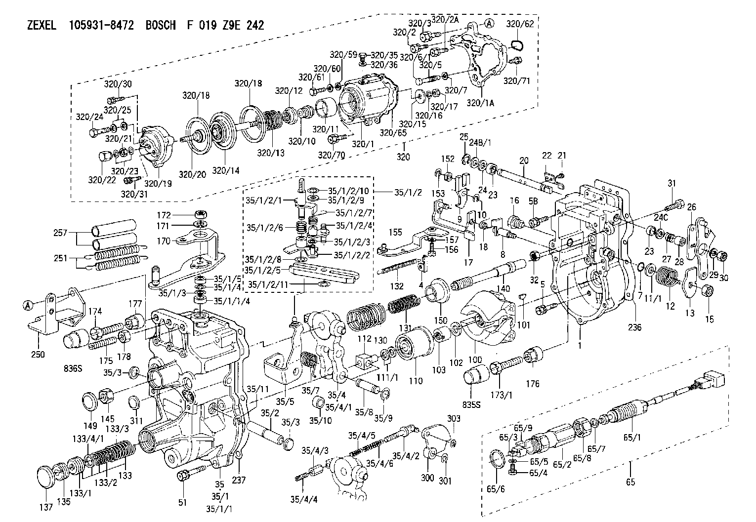
BOSCH
F 019 Z9E 242
f019z9e242
ZEXEL
105931-8472
1059318472
Rating:
Scheme ###:
| 1. | [1] | 159200-7620 | GOVERNOR HOUSING |
| 4. | [1] | 159232-0201 | PLATE |
| 5. | [8] | 139006-4100 | BLEEDER SCREW |
| 5B. | [2] | 139006-6000 | BLEEDER SCREW |
| 7. | [1] | 016530-1010 | O-RING |
| 8. | [1] | 159205-2321 | LEVER SHAFT |
| 9. | [1] | 159202-2301 | CONTROL LEVER |
| 10. | [1] | 016010-0810 | LOCKING WASHER |
| 11/1. | [0] | 029311-0220 | SHIM D18&10.3T0.2 |
| 11/1. | [0] | 029311-0230 | SHIM D18&10.3T0.5 |
| 11/1. | [0] | 029311-0430 | SHIM D18&10.3T0.30 |
| 11/1. | [0] | 029311-0440 | SHIM D18&10.3T0.40 |
| 11/1. | [0] | 029311-0450 | SHIM D18&10.3T0.25 |
| 11/1. | [0] | 029311-0460 | SHIM D18&10.3T0.35 |
| 11/1. | [0] | 139410-3300 | SHIM D18&10.3T0.6 |
| 11/1. | [0] | 139410-3400 | SHIM D18&10.3T0.8 |
| 11/1. | [0] | 139410-3500 | SHIM D18&10.3T0.9 |
| 12. | [1] | 159215-0000 | COILED SPRING |
| 13. | [1] | 159242-6601 | CONTROL LEVER |
| 15. | [1] | 013020-8040 | UNION NUT M8P1.25H7 |
| 16. | [1] | 159237-5500 | CAPSULE |
| 17. | [1] | 159202-5220 | CONTROL LEVER |
| 18. | [1] | 159215-0300 | COILED SPRING |
| 20. | [1] | 155004-5100 | LEVER SHAFT |
| 21. | [2] | 012154-1040 | FLAT-HEAD SCREW M4P0.7L10 |
| 22. | [1] | 159290-4000 | CONTROL LEVER |
| 23. | [2] | 139608-0400 | PACKING RING |
| 23. | [2] | 139608-0400 | PACKING RING |
| 24. | [1] | 139308-1900 | PLAIN WASHER |
| 24B/1. | [0] | 139408-1000 | SHIM D16&8T0.5 |
| 24B/1. | [0] | 139408-1300 | SHIM D16&8T0.2 |
| 24C. | [1] | 139308-1900 | PLAIN WASHER |
| 25. | [1] | 159238-4200 | LOCKING WASHER |
| 26. | [1] | 159290-7421 | CONTROL LEVER |
| 27. | [1] | 159215-5300 | COILED SPRING |
| 28. | [1] | 159230-3400 | BUSHING |
| 29. | [1] | 014110-8440 | LOCKING WASHER |
| 30. | [1] | 013020-8040 | UNION NUT M8P1.25H7 |
| 31. | [1] | 155644-1301 | BLEEDER SCREW |
| 32. | [1] | 013030-6040 | UNION NUT M6P1H3.6 |
| 35. | [1] | 159250-6420 | GOVERNOR COVER |
| 35/1. | [1] | 159301-2620 | GOVERNOR COVER |
| 35/1/1. | [1] | 159301-2520 | GOVERNOR COVER |
| 35/1/1/4. | [1] | 159230-2800 | BUSHING |
| 35/1/2. | [1] | 159252-3320 | LEVER GROUP |
| 35/1/2/1. | [1] | 159205-5420 | LEVER SHAFT |
| 35/1/2/2. | [1] | 159202-4810 | CONTROL LEVER |
| 35/1/2/3. | [1] | 029310-6030 | SHIM D11.5&6.2T0.2 |
| 35/1/2/4. | [1] | 159202-4520 | CONTROL LEVER |
| 35/1/2/5. | [1] | 159202-2200 | CONTROL LEVER |
| 35/1/2/6. | [1] | 159215-2301 | COILED SPRING |
| 35/1/2/7. | [1] | 159215-3900 | COILED SPRING |
| 35/1/2/8. | [1] | 016010-0810 | LOCKING WASHER |
| 35/1/2/9. | [1] | 014020-6140 | PLAIN WASHER |
| 35/1/2/10. | [1] | 016010-0610 | LOCKING WASHER |
| 35/1/2/11. | [1] | 016010-0810 | LOCKING WASHER |
| 35/1/3. | [1] | 139411-0600 | SHIM |
| 35/1/4. | [1] | 159238-3000 | LOCKING WASHER |
| 35/1/5. | [1] | 029621-0080 | PACKING RING |
| 35/2. | [1] | 159205-5500 | LEVER SHAFT |
| 35/3. | [2] | 159237-0200 | CAPSULE |
| 35/3. | [2] | 159237-0200 | CAPSULE |
| 35/4. | [1] | 159253-2220 | TENSIONING LEVER |
| 35/4/1. | [1] | 159203-1720 | TENSIONING LEVER |
| 35/4/2. | [1] | 159204-5021 | RACK |
| 35/4/3. | [1] | 159233-0300 | UNION NUT |
| 35/4/4. | [1] | 159234-0300 | FLAT-HEAD SCREW |
| 35/4/5. | [1] | 159216-0000 | COILED SPRING |
| 35/4/6. | [1] | 159216-0100 | COILED SPRING |
| 35/5. | [1] | 159203-6420 | GUIDE LEVER |
| 35/7. | [1] | 159215-5400 | COILED SPRING |
| 35/8. | [1] | 159231-1300 | BEARING PIN |
| 35/9. | [2] | 016010-0610 | LOCKING WASHER |
| 35/10. | [1] | 159238-4100 | BUSHING |
| 35/11. | [1] | 016010-1010 | LOCKING WASHER |
| 51. | [7] | 020106-3840 | BLEEDER SCREW |
| 65. | [1] | 154610-4620 | RACK SENSOR ASSY |
| 65/1. | [1] | 479742-2120 | RACK SENSOR |
| 65/2. | [1] | 154614-4800 | JOINT CONNECTION |
| 65/3. | [1] | 154614-5300 | BLOCK |
| 65/4. | [1] | 010234-1040 | HEX-SOCKET-HEAD CAP SCREW |
| 65/5. | [1] | 014110-4440 | LOCKING WASHER |
| 65/6. | [1] | 026524-3040 | GASKET |
| 65/7. | [1] | 029310-6280 | SHIM D11.5&6.4T1.50 |
| 65/8. | [1] | 154614-1900 | UNION NUT |
| 65/9. | [1] | 154614-3300 | BEARING PIN |
| 100. | [1] | 154100-9520 | FLYWEIGHT ASSEMBLY |
| 101. | [1] | 025803-1610 | WOODRUFF KEY |
| 102. | [1] | 029321-2020 | LOCKING WASHER |
| 103. | [1] | 029231-2030 | UNION NUT |
| 110. | [1] | 154123-2320 | SLIDING PIECE |
| 111/1. | [0] | 029311-0010 | SHIM D14&10.1T0.2 |
| 111/1. | [0] | 029311-0180 | SHIM D14&10.1T0.3 |
| 111/1. | [0] | 029311-0190 | SHIM D14&10.1T0.40 |
| 111/1. | [0] | 029311-0210 | SHIM D14&10.1T1 |
| 111/1. | [0] | 139410-0000 | SHIM D14.0&10.1T0.5 |
| 111/1. | [0] | 139410-0100 | SHIM D14.0&10.1T1.5 |
| 111/1. | [0] | 139410-3000 | SHIM D14&10.1T2.0 |
| 111/1. | [0] | 139410-3100 | SHIM D14&10.1T3.0 |
| 111/1. | [0] | 139410-3200 | SHIM D14&10.1T4.0 |
| 112. | [1] | 159236-0200 | TERMINAL STUD |
| 130. | [1] | 159210-3200 | GOVERNOR SPRING |
| 131. | [1] | 159211-1600 | GOVERNOR SPRING |
| 132. | [1] | 159214-0000 | COILED SPRING |
| 133. | [1] | 159212-7120 | SPRING PACK |
| 133/1. | [1] | 159234-5602 | GUIDE SLEEVE |
| 133/2. | [1] | 159212-5500 | COILED SPRING |
| 133/3. | [1] | 159212-3400 | COILED SPRING |
| 133/4/1. | [0] | 029310-9240 | SHIM D11.9&9T0.1 |
| 133/4/1. | [0] | 029310-9250 | SHIM D11.9&9T0.2 |
| 133/4/1. | [0] | 029310-9260 | SHIM D11.9&9T0.25 |
| 133/4/1. | [0] | 029310-9270 | SHIM D11.9&9T1.0 |
| 133/4/1. | [0] | 139409-0100 | SHIM D11.9&9T0.3 |
| 133/4/1. | [0] | 139409-0200 | SHIM D11.9&9T0.5 |
| 133/4/1. | [0] | 139409-0300 | SHIM D11.5&9T0.8 |
| 135. | [1] | 159248-2700 | FLAT-HEAD SCREW |
| 137. | [1] | 159237-5300 | CAPSULE |
| 140. | [1] | 159205-2101 | LEVER SHAFT |
| 145. | [1] | 159233-5700 | UNION NUT |
| 149. | [1] | 159237-5400 | CAPSULE |
| 150. | [1] | 159235-5300 | SLOTTED WASHER |
| 152. | [1] | 159235-5200 | BUSHING |
| 153. | [1] | 016010-0540 | LOCKING WASHER |
| 155. | [1] | 159204-6820 | STRAP |
| 156. | [1] | 010235-1020 | HEX-SOCKET-HEAD CAP SCREW |
| 157. | [1] | 029320-5020 | LOCKING WASHER |
| 170. | [1] | 159265-3420 | CONTROL LEVER |
| 171. | [1] | 014110-8440 | LOCKING WASHER |
| 172. | [1] | 013020-8040 | UNION NUT M8P1.25H7 |
| 173/1. | [1] | 139006-3500 | BLEEDER SCREW M6P1.0L33 |
| 173/1. | [1] | 139006-3700 | BLEEDER SCREW M6P1.0L34 |
| 173/1. | [1] | 139006-3800 | BLEEDER SCREW M6P1.0L35 |
| 173/1. | [1] | 139006-3900 | BLEEDER SCREW M6P1.0L36 |
| 173/1. | [1] | 139006-5300 | BLEEDER SCREW M6P1.0L31 |
| 173/1. | [1] | 139006-5400 | BLEEDER SCREW M6P1.0L32 |
| 173/1. | [1] | 155615-2500 | BLEEDER SCREW M6P1.0L37 |
| 174. | [1] | 154010-7200 | BLEEDER SCREW M8P1.25L62 |
| 175. | [1] | 154010-0100 | FLAT-HEAD SCREW |
| 176. | [1] | 159225-8600 | UNION NUT |
| 177. | [1] | 154011-2300 | UNION NUT |
| 178. | [1] | 154011-0100 | HEXAGON NUT |
| 236. | [1] | 159238-4000 | GASKET |
| 237. | [1] | 159238-3100 | GASKET |
| 250. | [1] | 159220-6221 | BRACKET |
| 251. | [2] | 154332-4600 | COILED SPRING |
| 257. | [2] | 154156-2300 | TUBE |
| 300. | [1] | 159283-4700 | CAM PLATE |
| 301. | [1] | 016010-0840 | LOCKING WASHER |
| 303. | [1] | 016010-0540 | LOCKING WASHER |
| 311. | [1] | 159237-0200 | CAPSULE |
| 320. | [1] | 154419-9120 | MANIFOLD-PRESSURE COMP. |
| 320/1. | [1] | 154413-6420 | DIAPHRAGM HOUSING |
| 320/1A. | [1] | 154413-6500 | SPACER BUSHING |
| 320/2. | [1] | 020106-2240 | BLEEDER SCREW |
| 320/2A. | [2] | 020106-2540 | BLEEDER SCREW M6P1L25 |
| 320/3. | [1] | 020118-3040 | BLEEDER SCREW |
| 320/5. | [1] | 159275-1400 | COILED SPRING |
| 320/6/1. | [1] | 159274-0120 | STOP PIN L125 |
| 320/6/1. | [1] | 159274-0220 | STOP PIN L127.50 |
| 320/6/1. | [1] | 159274-0320 | STOP PIN L128.00 |
| 320/6/1. | [1] | 159274-0420 | STOP PIN L127.00 |
| 320/6/1. | [1] | 159274-0520 | STOP PIN L126.00 |
| 320/6/1. | [1] | 159274-0620 | STOP PIN L129.00 |
| 320/6/1. | [1] | 159274-0720 | STOP PIN L128.50 |
| 320/6/1. | [1] | 159274-0820 | STOP PIN L125.50 |
| 320/6/1. | [1] | 159274-0920 | STOP PIN L126.50 |
| 320/6/1. | [1] | 159274-1120 | STOP PIN L119.5 |
| 320/6/1. | [1] | 159274-1220 | STOP PIN L120 |
| 320/6/1. | [1] | 159274-1320 | STOP PIN L120.5 |
| 320/6/1. | [1] | 159274-1420 | STOP PIN L121 |
| 320/6/1. | [1] | 159274-1520 | STOP PIN L121.5 |
| 320/6/1. | [1] | 159274-1620 | STOP PIN L122 |
| 320/6/1. | [1] | 159274-1720 | STOP PIN L122.5 |
| 320/6/1. | [1] | 159274-1820 | STOP PIN L123 |
| 320/6/1. | [1] | 159274-1920 | STOP PIN L123.5 |
| 320/6/1. | [1] | 159274-4220 | STOP PIN L129.5 |
| 320/6/1. | [1] | 159274-4320 | STOP PIN L130 |
| 320/6/1. | [1] | 159274-4420 | STOP PIN L130.5 |
| 320/6/1. | [1] | 159274-4520 | STOP PIN L131 |
| 320/6/1. | [1] | 159274-4620 | STOP PIN L131.5 |
| 320/6/1. | [1] | 159274-4720 | STOP PIN L132 |
| 320/6/1. | [1] | 159274-4820 | STOP PIN L132.5 |
| 320/6/1. | [1] | 159274-4920 | STOP PIN L133 |
| 320/6/1. | [1] | 159274-5020 | STOP PIN L133.5 |
| 320/7. | [1] | 014010-5140 | PLAIN WASHER D12&5.5T0.8 |
| 320/10. | [1] | 154413-3600 | BUSHING |
| 320/11. | [1] | 146711-0000 | PLATE |
| 320/12. | [1] | 146716-0000 | UNION NUT |
| 320/13. | [1] | 154403-3800 | COILED SPRING |
| 320/14. | [1] | 154415-4320 | DIAPHRAGM |
| 320/15. | [1] | 154406-5500 | SLOTTED WASHER |
| 320/16. | [1] | 014110-6440 | LOCKING WASHER |
| 320/17. | [1] | 013030-6040 | UNION NUT M6P1H3.6 |
| 320/18. | [2] | 154413-2600 | GASKET |
| 320/18. | [2] | 154413-2600 | GASKET |
| 320/19. | [1] | 154404-5000 | COVER |
| 320/20. | [1] | 154413-4000 | FLAT-HEAD SCREW |
| 320/21. | [1] | 013030-6040 | UNION NUT M6P1H3.6 |
| 320/22. | [1] | 154035-1600 | CAP NUT |
| 320/23. | [2] | 139506-0300 | GASKET |
| 320/24. | [1] | 029731-0180 | EYE BOLT |
| 320/25. | [2] | 139510-0200 | GASKET |
| 320/30. | [1] | 020106-3040 | BLEEDER SCREW |
| 320/31. | [2] | 029010-6540 | BLEEDER SCREW |
| 320/35. | [1] | 029111-2090 | CAPSULE |
| 320/36. | [1] | 139512-0000 | GASKET D17.2&12.2T1.0 |
| 320/59. | [1] | 014010-6140 | PLAIN WASHER D13&6.5T1 |
| 320/60. | [1] | 139505-0000 | PLAIN WASHER |
| 320/61. | [1] | 010006-1670 | BLEEDER SCREW M6P1L16 7T |
| 320/62. | [1] | 159226-4500 | SPACER RING |
| 320/65. | [1] | 154390-1900 | GASKET |
| 320/70. | [2] | 020106-2040 | BLEEDER SCREW M6P1L20 |
| 320/71. | [3] | 020106-2240 | BLEEDER SCREW |
| 835S. | [1] | 154062-1900 | CAP D12L24 |
| 836S. | [1] | 154062-1700 | CAP D20L32 |
Include in #1:
107692-1052
as GOVERNOR
Cross reference number
Zexel num
Bosch num
Firm num
Name
Information:
Make reference to Guideline For Reusable Parts; Pistons, Form No. SEBF8049; Cylinder Liners, Form No. SEBF8068; and Piston Pins And Retaining Rings, Form No. SEBF8051. For installation, number on tab groove side of connecting rod is to be positioned toward opposite side of engine from camshaft.Top And Intermediate Ring
The 8T3150 Keystone Piston Ring Groove Gauge is necessary for measuring ring groove in keystone style pistons. For correct use of the gauge group, see the instruction card that is with the gauge group.Install piston rings with "UP" side toward top of piston.(1) Top Ring has the mark "UP-1."(2) Intermediate ring has the mark "UP-2".Clearance between ends of piston ring when installed in a cylinder liner with a bore size of 137.16 mm (5.400 in)Top ring ... 0.724 0.191 mm (.0285 .0075 in)Intermediate ring ... 1.080 0.190 mm (.0425 .0075 in)Increase in clearance between ends of piston rings for each 0.03 mm (.001 in) increase in cylinder liner bore size ... 0.08 mm (.003 in)Oil Control Ring
(3) Install oil control ring with the gap in the spring 180° away from the gap in the ring. White portion of spring must be visible at the ring end gap.Width of groove in piston for piston ring (new) ... 3.210 0.010 mm (.1264 .0004 in)Thickness of piston ring (new) ... 3.137 0.013 mm (.1235 .0005 in)Clearance between groove and piston ring (new) ... 0.073 0.023 mm (.0029 .0009 in)Maximum permissible clearance (worn) ... 0.15 mm (.006 in)Clearance between ends of piston ring when installed in a cylinder liner with a bore size of 137.16 mm (5.400 in) ... 0.572 0.191 mm (.0225 .0075 in)Increase in clearance between ends of piston ring for each 0.03 mm (.001 in) increase in cylinder liner bore size ... 0.08 mm (.003 in)Piston Pin Bore
(4) Bore in piston for pin. 1991 Model with elliptical pin bore (310 - 425 hp) Vertical ... 50.814 0.004 mm (2.0005 .0001 in)Horizontal ... actual vertical diameter plus 0.032 to 0.048 mm (.0012 to .0019 in)Clearance between pin and bore in piston ... 0.010 to 0.028 mm (.0004 to .0011 in)Permissible clearance (worn) ... 0.05 mm (.002 in)Pin diameter ... 50.795 0.005 mm (1.9998 .0002 in) Low Crevice Volume and Gallery Pistons Bore in piston for pin ... 50.814 0.004 mm (2.0005 .0001 in)Clearance between pin and bore in piston ... 0.010 to 0.028 mm (.0004 to .0011 in)Permissible clearance (worn) ... 0.05 mm (.002 in)Pin diameter ... 50.795 0.005 mm (1.9998 .0002 in)All Other Pistons Bore in piston for pin ... 50.815 0.008 mm (2.0006 .0003 in)Clearance between pin and bore in piston ... 0.007 to 0.032 mm (.0003 to .0013 in)Permissible clearance (worn) ... 0.05 mm (.002 in)Pin diameter ... 50.795 0.005 mm (1.9998 .0002 in)