Information governor
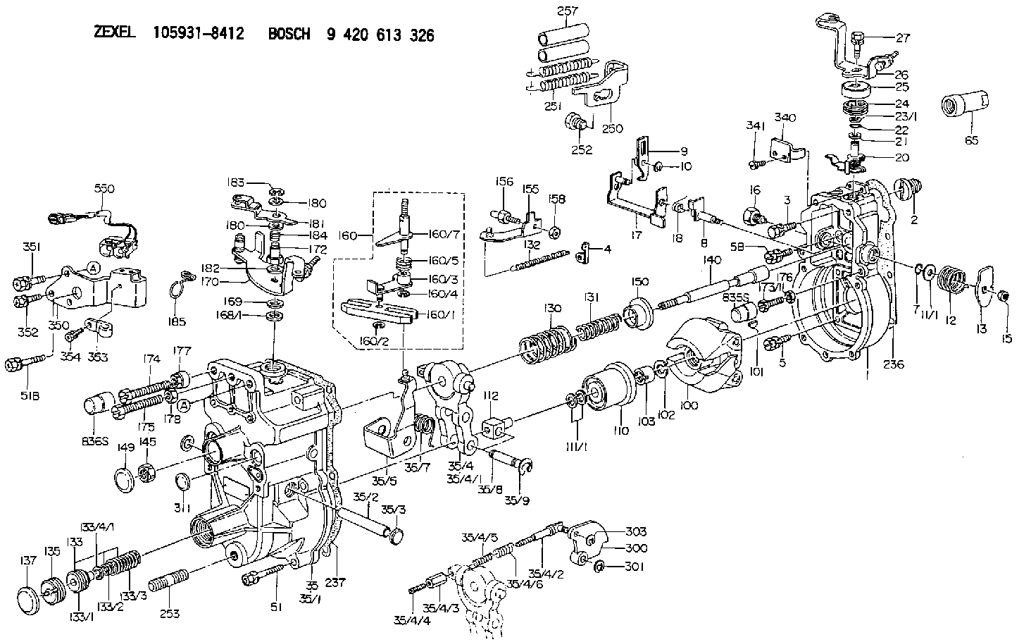
BOSCH
9 420 613 626
9420613626
ZEXEL
105931-8412
1059318412
MITSUBISHI
ME738890
me738890
Rating:
Scheme ###:
| 1. | [1] | 159200-4920 | GOVERNOR HOUSING |
| 2. | [1] | 154007-0200 | ADAPTOR |
| 3. | [1] | 020018-1840 | BLEEDER SCREW M8P1.25L18 |
| 4. | [1] | 159232-0201 | PLATE |
| 5. | [5] | 029010-6810 | BLEEDER SCREW |
| 5B. | [1] | 020106-1640 | BLEEDER SCREW M6P1.0L14 |
| 7. | [1] | 016530-1010 | O-RING |
| 8. | [1] | 159205-2321 | LEVER SHAFT |
| 9. | [1] | 159202-1802 | CONTROL LEVER |
| 10. | [1] | 016010-0810 | LOCKING WASHER |
| 11/1. | [0] | 029311-0220 | SHIM D18&10.3T0.2 |
| 11/1. | [0] | 029311-0230 | SHIM D18&10.3T0.5 |
| 11/1. | [0] | 029311-0430 | SHIM D18&10.3T0.30 |
| 11/1. | [0] | 029311-0440 | SHIM D18&10.3T0.40 |
| 11/1. | [0] | 029311-0450 | SHIM D18&10.3T0.25 |
| 11/1. | [0] | 029311-0460 | SHIM D18&10.3T0.35 |
| 11/1. | [0] | 139410-3300 | SHIM D18&10.3T0.6 |
| 11/1. | [0] | 139410-3400 | SHIM D18&10.3T0.8 |
| 11/1. | [0] | 139410-3500 | SHIM D18&10.3T0.9 |
| 12. | [1] | 159215-0000 | COILED SPRING |
| 13. | [1] | 159242-6601 | CONTROL LEVER |
| 15. | [1] | 013020-8040 | UNION NUT M8P1.25H7 |
| 16. | [1] | 159237-5200 | CAPSULE |
| 17. | [1] | 159202-1920 | CONTROL LEVER |
| 18. | [1] | 159215-0300 | COILED SPRING |
| 20. | [1] | 159242-0220 | CONTROL LEVER |
| 21. | [1] | 159242-0600 | BUSHING |
| 22. | [1] | 016530-1010 | O-RING |
| 23/1. | [0] | 029311-0220 | SHIM D18&10.3T0.2 |
| 23/1. | [0] | 029311-0230 | SHIM D18&10.3T0.5 |
| 23/1. | [0] | 029311-0430 | SHIM D18&10.3T0.30 |
| 23/1. | [0] | 029311-0440 | SHIM D18&10.3T0.40 |
| 23/1. | [0] | 029311-0450 | SHIM D18&10.3T0.25 |
| 23/1. | [0] | 029311-0460 | SHIM D18&10.3T0.35 |
| 23/1. | [0] | 139410-3300 | SHIM D18&10.3T0.6 |
| 23/1. | [0] | 139410-3400 | SHIM D18&10.3T0.8 |
| 23/1. | [0] | 139410-3500 | SHIM D18&10.3T0.9 |
| 24. | [1] | 159215-2000 | COILED SPRING |
| 25. | [1] | 159235-5800 | CAP |
| 26. | [1] | 159249-6920 | CONTROL LEVER |
| 27. | [1] | 020006-1640 | BLEEDER SCREW M6P1L16 4T |
| 35. | [1] | 159251-3920 | GOVERNOR COVER |
| 35/1. | [1] | 159201-3422 | GOVERNOR COVER |
| 35/2. | [1] | 159205-0400 | LEVER SHAFT |
| 35/3. | [2] | 159237-0200 | CAPSULE |
| 35/4. | [1] | 159253-0720 | TENSIONING LEVER |
| 35/4/1. | [1] | 159203-0720 | TENSIONING LEVER |
| 35/4/2. | [1] | 159204-5021 | RACK |
| 35/4/3. | [1] | 159233-0300 | UNION NUT |
| 35/4/4. | [1] | 159234-0300 | FLAT-HEAD SCREW |
| 35/4/5. | [1] | 159216-0000 | COILED SPRING |
| 35/4/6. | [1] | 159216-0100 | COILED SPRING |
| 35/5. | [1] | 159203-5720 | GUIDE LEVER |
| 35/7. | [1] | 159215-1701 | COILED SPRING |
| 35/8. | [1] | 159231-2000 | BEARING PIN |
| 35/9. | [2] | 016010-0610 | LOCKING WASHER |
| 51. | [6] | 020106-3840 | BLEEDER SCREW |
| 51B. | [1] | 020106-4040 | BLEEDER SCREW |
| 65. | [1] | 154050-1720 | STOPPING DEVICE |
| 100. | [1] | 154100-9520 | FLYWEIGHT ASSEMBLY |
| 101. | [1] | 025803-1610 | WOODRUFF KEY |
| 102. | [1] | 029321-2020 | LOCKING WASHER |
| 103. | [1] | 029231-2030 | UNION NUT |
| 110. | [1] | 154123-2320 | SLIDING PIECE |
| 111/1. | [0] | 029311-0010 | SHIM D14&10.1T0.2 |
| 111/1. | [0] | 029311-0180 | SHIM D14&10.1T0.3 |
| 111/1. | [0] | 029311-0190 | SHIM D14&10.1T0.40 |
| 111/1. | [0] | 029311-0210 | SHIM D14&10.1T1 |
| 111/1. | [0] | 139410-0000 | SHIM D14.0&10.1T0.5 |
| 111/1. | [0] | 139410-0100 | SHIM D14.0&10.1T1.5 |
| 111/1. | [0] | 139410-3000 | SHIM D14&10.1T2.0 |
| 111/1. | [0] | 139410-3100 | SHIM D14&10.1T3.0 |
| 111/1. | [0] | 139410-3200 | SHIM D14&10.1T4.0 |
| 112. | [1] | 159236-0200 | TERMINAL STUD |
| 130. | [1] | 159210-0700 | GOVERNOR SPRING |
| 131. | [1] | 159211-2600 | COILED SPRING |
| 132. | [1] | 159214-0000 | COILED SPRING |
| 133. | [1] | 159212-5920 | SPRING PACK |
| 133/1. | [1] | 159234-5602 | GUIDE SLEEVE |
| 133/2. | [1] | 159212-4700 | COILED SPRING |
| 133/3. | [1] | 159212-5700 | COILED SPRING |
| 133/4/1. | [0] | 029310-9240 | SHIM D11.9&9T0.1 |
| 133/4/1. | [0] | 029310-9250 | SHIM D11.9&9T0.2 |
| 133/4/1. | [0] | 029310-9260 | SHIM D11.9&9T0.25 |
| 133/4/1. | [0] | 029310-9270 | SHIM D11.9&9T1.0 |
| 133/4/1. | [0] | 139409-0100 | SHIM D11.9&9T0.3 |
| 133/4/1. | [0] | 139409-0200 | SHIM D11.9&9T0.5 |
| 133/4/1. | [0] | 139409-0300 | SHIM D11.5&9T0.8 |
| 135. | [1] | 159248-2700 | FLAT-HEAD SCREW |
| 137. | [1] | 159237-5300 | CAPSULE |
| 140. | [1] | 159205-2101 | LEVER SHAFT |
| 145. | [1] | 159233-5700 | UNION NUT |
| 149. | [1] | 159237-5400 | CAPSULE |
| 150. | [1] | 159235-5300 | SLOTTED WASHER |
| 155. | [1] | 159204-5120 | STRAP |
| 156. | [1] | 159233-5800 | BLEEDER SCREW |
| 158. | [1] | 013020-5240 | UNION NUT M5P0.8H4 |
| 160. | [1] | 159252-0821 | LEVER GROUP |
| 160/1. | [1] | 159202-2200 | CONTROL LEVER |
| 160/2. | [1] | 016010-0810 | LOCKING WASHER |
| 160/3. | [1] | 159202-2120 | CONTROL LEVER |
| 160/4. | [1] | 016010-0810 | LOCKING WASHER |
| 160/5. | [1] | 159215-2301 | COILED SPRING |
| 160/7. | [1] | 159205-2222 | LEVER SHAFT |
| 168/1. | [0] | 029311-0640 | SHIM D26.0&10.2T0.95 |
| 168/1. | [0] | 029311-0650 | SHIM D26.0&10.2T0.20 |
| 168/1. | [0] | 029311-0660 | SHIM D26.0&10.2T0.25 |
| 168/1. | [0] | 029311-0670 | SHIM D26.0&10.2T0.30 |
| 168/1. | [0] | 029311-0680 | SHIM D26.0&10.2T0.35 |
| 168/1. | [0] | 029311-0690 | SHIM D26.0&10.2T0.40 |
| 168/1. | [0] | 029311-0700 | SHIM D26.0&10.2T0.50 |
| 168/1. | [0] | 139410-1400 | SHIM D26&10.2T0.7 |
| 168/1. | [0] | 139410-1500 | SHIM D26&10.2T0.9 |
| 168/1. | [0] | 139410-1600 | SHIM D26&10.2T0.8 |
| 168/1. | [0] | 139410-2700 | SHIM D26&10.2T0.6 |
| 169. | [1] | 139410-2300 | SHIM |
| 170. | [1] | 159264-3220 | CONTROL LEVER |
| 172. | [1] | 159231-4400 | UNION NUT |
| 173/1. | [1] | 139006-3500 | BLEEDER SCREW M6P1.0L33 |
| 173/1. | [1] | 139006-3700 | BLEEDER SCREW M6P1.0L34 |
| 173/1. | [1] | 139006-3800 | BLEEDER SCREW M6P1.0L35 |
| 173/1. | [1] | 139006-3900 | BLEEDER SCREW M6P1.0L36 |
| 173/1. | [1] | 139006-5300 | BLEEDER SCREW M6P1.0L31 |
| 173/1. | [1] | 139006-5400 | BLEEDER SCREW M6P1.0L32 |
| 173/1. | [1] | 155615-2500 | BLEEDER SCREW M6P1.0L37 |
| 174. | [1] | 154010-7200 | BLEEDER SCREW M8P1.25L62 |
| 175. | [1] | 154010-2900 | BLEEDER SCREW |
| 176. | [1] | 159225-8600 | UNION NUT |
| 177. | [1] | 154011-2300 | UNION NUT |
| 178. | [1] | 154011-0100 | HEXAGON NUT |
| 180. | [2] | 154371-0000 | PLAIN WASHER |
| 180. | [2] | 154371-0000 | PLAIN WASHER |
| 181. | [1] | 159262-5520 | CONTROL LEVER |
| 182. | [1] | 029300-8010 | PLAIN WASHER D15&8T1.00 |
| 183. | [1] | 016010-0740 | LOCKING WASHER |
| 184. | [1] | 159215-4600 | COILED SPRING |
| 185. | [1] | 159229-7500 | CLAMPING BAND |
| 236. | [1] | 154390-0000 | GASKET |
| 237. | [1] | 159238-3100 | GASKET |
| 250. | [1] | 159229-2520 | BRACKET |
| 251. | [2] | 159243-9900 | COILED SPRING |
| 252. | [1] | 159248-0200 | BLEEDER SCREW |
| 253. | [1] | 139010-1000 | STUD |
| 257. | [2] | 154156-0500 | TUBE |
| 300. | [1] | 159282-4700 | CAM PLATE |
| 301. | [1] | 016010-0840 | LOCKING WASHER |
| 303. | [1] | 016010-0540 | LOCKING WASHER |
| 311. | [1] | 159237-0200 | CAPSULE |
| 340. | [1] | 159245-8300 | PLATE |
| 341. | [2] | 020104-1040 | BLEEDER SCREW |
| 350. | [1] | 159227-7800 | BRACKET |
| 351. | [1] | 020118-1440 | BLEEDER SCREW |
| 352. | [2] | 020106-1240 | BLEEDER SCREW M6P1.0L12 |
| 353. | [1] | 159225-5120 | PLATE |
| 354. | [1] | 020106-0840 | BLEEDER SCREW |
| 550. | [1] | 153169-4820 | MICROSWITCH |
Include in #1:
101607-1581
as GOVERNOR
Cross reference number
Zexel num
Bosch num
Firm num
Name
Information:
Pressure Control Function For Actuation And Deactuation Of Models KPS 35 (specifically shown for the 4W-2642 Contactor) And KPS 37
Adjusting Pressure And Differential Settings On A 4W-2642 (KPS 35) Pressure Contactor
This example shows the pressure set at 38 psi with a 7 psi mechanical differential pressure setting. This results in an actuation pressure of 45 psi and deactuation pressure of 38 psi. Refer to the "Pressure Control Function For Actuation And Deactuation Of Models KPS 35 And KPS 37" illustration.8. Increase the air supply to the desired actuation pressure.9. When the actuation pressure has stabilized, very slowly turn range spindle (5) counterclockwise until the contact actuates. This will be accompanied by an audible "click".
When Contact Actuates, Terminals 1 And 4 Will Have Continuity10. Use a 6V-7070 Multimeter, or equivalent, to verify the actuation of the contactor. Check for continuity between terminals 1 and 4. If there is no continuity, the contactor has not actuated; continue to adjust the range spindle until there is continuity between terminals 1 and 4.11. Slowly bleed off the air pressure until the contact deactuates. Again, this will be accompanied by an audible "click".
When Contact Deactuates, Terminals 1 And 2 Will Have Continuity12. Verify the deactuation of the contactor by checking for continuity between terminals 1 and 2. If there is no continuity, the contactor has not deactuated. Continue to decrease the pressure until it does. Record this deactuation pressure.13. Again, slowly increase the air pressure until the contact actuates. This gives an accurate indication of the actual actuation setting. If the actuation setting is not correct (too high or too low), adjust range spindle (5) until the required actuation setting is reached.14. Once the actuation setting is established, the deactuation setting can be slightly raised or lowered by adjusting differential spindle (7). Adjusting differential spindle (7) generally will not affect the actuation setting, but it is advisable to recheck it after any adjustment.15. Continue to adjust differential spindle (7) until the deactuation set setting is established.16. Tighten lock screw (4) when both pressure settings have been established.17. Make a final pressure check to make sure the actuation and deactuation settings have not changed. The contactor is now set and ready to be installed.18. Replace housing cover (1) using housing cover screws (2).Calibration Procedure for Model KPS 31 Contactors
Use the following procedure to test and calibrate pressure contactor models KPS 31 and CAS 143. To calibrate CAS 143 model pressure contactors without differential pressure mechanisms, refer to the "Calibration of Pressure Contactors Without a Differential Pressure Mechanism (Model CAS 143)" section in this Special Instruction.1. If connected, disconnect the contactor from the power supply. Mark terminal locations and disconnect the three wires from terminals 1, 2, and 4.
High voltage electrical shock is possible. The contactor must be disconnected from the power supply and the wires disconnected from terminals 1, 2, and 4. Failure to follow this recommendation can result in serious bodily injury.
2. Locate and record the part number of the pressure contactor in