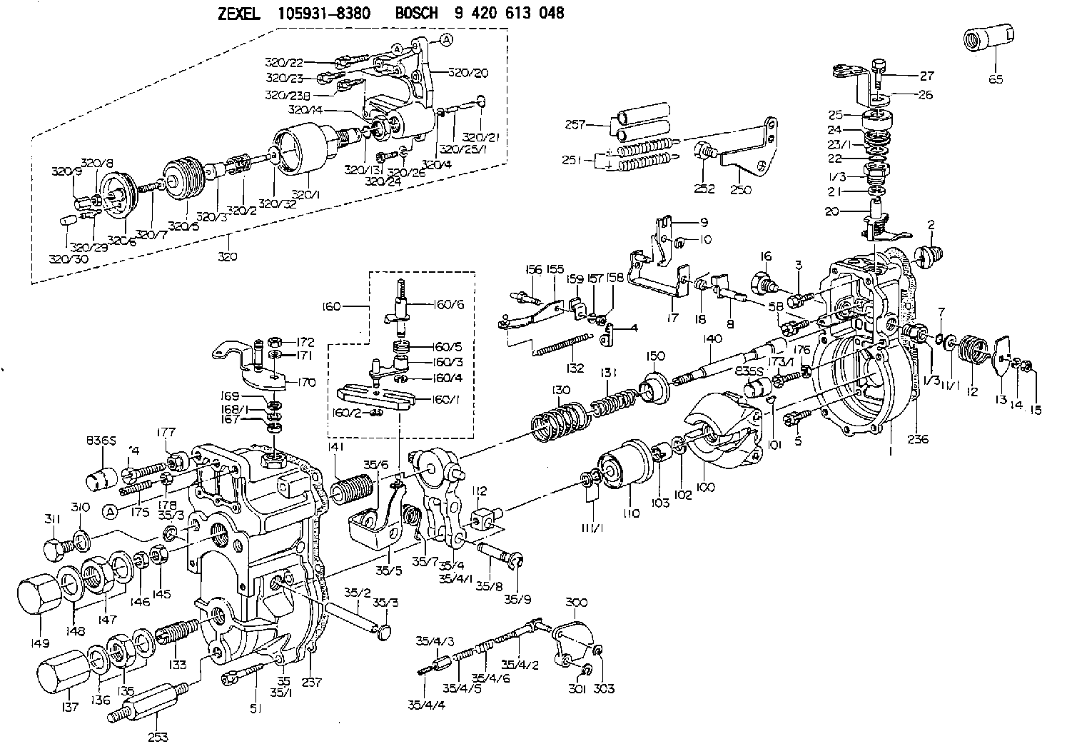
Information governor
BOSCH
9 420 613 048
9420613048
ZEXEL
105931-8380
1059318380
ISUZU
8970331550
8970331550

Rating:
Scheme ###:
| 1. | [1] | 159200-1420 | GOVERNOR HOUSING |
| 1/3. | [2] | 154321-0400 | BUSHING |
| 1/3. | [2] | 154321-0400 | BUSHING |
| 2. | [1] | 154007-0200 | ADAPTOR |
| 3. | [1] | 020018-1840 | BLEEDER SCREW M8P1.25L18 |
| 4. | [1] | 159232-0201 | PLATE |
| 5. | [5] | 029010-6810 | BLEEDER SCREW |
| 5B. | [1] | 020106-1640 | BLEEDER SCREW M6P1.0L14 |
| 7. | [1] | 029631-0030 | O-RING &9.8W2.3 |
| 8. | [1] | 159205-2321 | LEVER SHAFT |
| 9. | [1] | 159202-0400 | CONTROL LEVER |
| 10. | [1] | 016010-0810 | LOCKING WASHER |
| 11/1. | [0] | 029311-0520 | SHIM D20.8&10.3T0.2 |
| 11/1. | [0] | 029311-0530 | SHIM D20.8&10.3T0.25 |
| 11/1. | [0] | 029311-0540 | SHIM D20.8&10.3T0.3 |
| 11/1. | [0] | 029311-0550 | SHIM D20.8&10.3T0.35 |
| 11/1. | [0] | 029311-0560 | SHIM D20.8&10.3T0.4 |
| 11/1. | [0] | 029311-0570 | SHIM D20.8&10.3T0.5 |
| 12. | [1] | 159215-0000 | COILED SPRING |
| 13. | [1] | 159242-0100 | CONTROL LEVER |
| 14. | [1] | 014110-8440 | LOCKING WASHER |
| 15. | [1] | 013020-8040 | UNION NUT M8P1.25H7 |
| 16. | [1] | 159237-0000 | CAPSULE |
| 17. | [1] | 159202-0920 | CONTROL LEVER |
| 18. | [1] | 159215-0300 | COILED SPRING |
| 20. | [1] | 159242-0220 | CONTROL LEVER |
| 21. | [1] | 159242-0600 | BUSHING |
| 22. | [1] | 029631-0030 | O-RING &9.8W2.3 |
| 23/1. | [0] | 029311-0220 | SHIM D18&10.3T0.2 |
| 23/1. | [0] | 029311-0230 | SHIM D18&10.3T0.5 |
| 23/1. | [0] | 029311-0430 | SHIM D18&10.3T0.30 |
| 23/1. | [0] | 029311-0440 | SHIM D18&10.3T0.40 |
| 23/1. | [0] | 029311-0450 | SHIM D18&10.3T0.25 |
| 23/1. | [0] | 029311-0460 | SHIM D18&10.3T0.35 |
| 23/1. | [0] | 139410-3300 | SHIM D18&10.3T0.6 |
| 23/1. | [0] | 139410-3400 | SHIM D18&10.3T0.8 |
| 23/1. | [0] | 139410-3500 | SHIM D18&10.3T0.9 |
| 24. | [1] | 159215-0000 | COILED SPRING |
| 25. | [1] | 154322-0100 | CAP |
| 26. | [1] | 159242-2920 | CONTROL LEVER |
| 27. | [1] | 020006-1640 | BLEEDER SCREW M6P1L16 4T |
| 35. | [1] | 159251-3120 | GOVERNOR COVER |
| 35/1. | [1] | 159201-2920 | GOVERNOR COVER |
| 35/2. | [1] | 159205-0400 | LEVER SHAFT |
| 35/3. | [2] | 159237-0200 | CAPSULE |
| 35/3. | [2] | 159237-0200 | CAPSULE |
| 35/4. | [1] | 159253-0120 | TENSIONING LEVER |
| 35/4/1. | [1] | 159203-0120 | TENSIONING LEVER |
| 35/4/2. | [1] | 159204-5021 | RACK |
| 35/4/3. | [1] | 159233-0300 | UNION NUT |
| 35/4/4. | [1] | 159234-0000 | FLAT-HEAD SCREW |
| 35/4/5. | [1] | 159216-0000 | COILED SPRING |
| 35/4/6. | [1] | 159216-0100 | COILED SPRING |
| 35/5. | [1] | 159203-5020 | GUIDE LEVER |
| 35/6. | [2] | 159235-5000 | BUSHING |
| 35/7. | [1] | 159215-0201 | COILED SPRING |
| 35/8. | [1] | 159231-0800 | BEARING PIN |
| 35/9. | [2] | 016010-0610 | LOCKING WASHER |
| 51. | [7] | 020106-3840 | BLEEDER SCREW |
| 65. | [1] | 154050-1720 | STOPPING DEVICE |
| 100. | [1] | 154101-0420 | FLYWEIGHT ASSEMBLY |
| 101. | [1] | 025803-1610 | WOODRUFF KEY |
| 102. | [1] | 029321-2020 | LOCKING WASHER |
| 103. | [1] | 029231-2030 | UNION NUT |
| 110. | [1] | 154123-1020 | SLIDING PIECE |
| 111/1. | [0] | 029311-0010 | SHIM D14&10.1T0.2 |
| 111/1. | [0] | 029311-0180 | SHIM D14&10.1T0.3 |
| 111/1. | [0] | 029311-0190 | SHIM D14&10.1T0.40 |
| 111/1. | [0] | 029311-0210 | SHIM D14&10.1T1 |
| 111/1. | [0] | 139410-0000 | SHIM D14.0&10.1T0.5 |
| 111/1. | [0] | 139410-0100 | SHIM D14.0&10.1T1.5 |
| 111/1. | [0] | 139410-3000 | SHIM D14&10.1T2.0 |
| 111/1. | [0] | 139410-3100 | SHIM D14&10.1T3.0 |
| 111/1. | [0] | 139410-3200 | SHIM D14&10.1T4.0 |
| 112. | [1] | 159236-0100 | TERMINAL STUD |
| 130. | [1] | 159210-2000 | GOVERNOR SPRING |
| 131. | [1] | 159211-0400 | GOVERNOR SPRING |
| 132. | [1] | 159214-0100 | COILED SPRING |
| 133. | [1] | 159212-1620 | HEADLESS SCREW |
| 135. | [1] | 139220-0200 | UNION NUT |
| 136. | [2] | 026520-2440 | GASKET D23.9&20.2T1 |
| 137. | [1] | 159248-0700 | CAP |
| 140. | [1] | 159205-0301 | LEVER SHAFT |
| 141. | [1] | 159234-5200 | GUIDE SLEEVE |
| 145. | [1] | 159233-5000 | UNION NUT |
| 146. | [1] | 023020-8040 | UNION NUT M8P1H5 |
| 147. | [1] | 139222-0200 | UNION NUT |
| 148. | [2] | 026522-2740 | GASKET D26.9&22.2T1 |
| 149. | [1] | 159237-5000 | CAP |
| 150. | [1] | 159235-5300 | SLOTTED WASHER |
| 155. | [1] | 159204-0120 | STRAP |
| 156. | [1] | 159237-0300 | BLEEDER SCREW |
| 157. | [1] | 014110-5440 | LOCKING WASHER |
| 158. | [1] | 159233-5200 | UNION NUT |
| 159. | [1] | 159242-0800 | PLATE |
| 160. | [1] | 159252-0122 | LEVER GROUP |
| 160/1. | [1] | 159202-2200 | CONTROL LEVER |
| 160/2. | [1] | 016010-0810 | LOCKING WASHER |
| 160/3. | [1] | 159202-0220 | CONTROL LEVER |
| 160/4. | [1] | 016010-0810 | LOCKING WASHER |
| 160/5. | [1] | 159215-0400 | COILED SPRING |
| 160/6. | [1] | 159205-0621 | LEVER SHAFT |
| 167. | [1] | 029621-0080 | PACKING RING |
| 168/1. | [0] | 029311-0640 | SHIM D26.0&10.2T0.95 |
| 168/1. | [0] | 029311-0650 | SHIM D26.0&10.2T0.20 |
| 168/1. | [0] | 029311-0660 | SHIM D26.0&10.2T0.25 |
| 168/1. | [0] | 029311-0670 | SHIM D26.0&10.2T0.30 |
| 168/1. | [0] | 029311-0680 | SHIM D26.0&10.2T0.35 |
| 168/1. | [0] | 029311-0690 | SHIM D26.0&10.2T0.40 |
| 168/1. | [0] | 029311-0700 | SHIM D26.0&10.2T0.50 |
| 168/1. | [0] | 139410-1400 | SHIM D26&10.2T0.7 |
| 168/1. | [0] | 139410-1500 | SHIM D26&10.2T0.9 |
| 168/1. | [0] | 139410-1600 | SHIM D26&10.2T0.8 |
| 168/1. | [0] | 139410-2700 | SHIM D26&10.2T0.6 |
| 169. | [1] | 139410-2300 | SHIM |
| 170. | [1] | 159241-9420 | CONTROL LEVER |
| 171. | [1] | 014110-8440 | LOCKING WASHER |
| 172. | [1] | 013020-8040 | UNION NUT M8P1.25H7 |
| 173/1. | [1] | 139006-3500 | BLEEDER SCREW M6P1.0L33 |
| 173/1. | [1] | 139006-3700 | BLEEDER SCREW M6P1.0L34 |
| 173/1. | [1] | 139006-3800 | BLEEDER SCREW M6P1.0L35 |
| 173/1. | [1] | 139006-3900 | BLEEDER SCREW M6P1.0L36 |
| 173/1. | [1] | 139006-5300 | BLEEDER SCREW M6P1.0L31 |
| 173/1. | [1] | 139006-5400 | BLEEDER SCREW M6P1.0L32 |
| 173/1. | [1] | 155615-2500 | BLEEDER SCREW M6P1.0L37 |
| 174. | [1] | 154010-7200 | BLEEDER SCREW M8P1.25L62 |
| 175. | [1] | 154010-0100 | FLAT-HEAD SCREW |
| 176. | [1] | 159225-8600 | UNION NUT |
| 177. | [1] | 154011-2300 | UNION NUT |
| 178. | [1] | 154011-0100 | HEXAGON NUT |
| 236. | [1] | 154390-0000 | GASKET |
| 237. | [1] | 159238-3100 | GASKET |
| 250. | [1] | 159245-2820 | BRACKET |
| 251. | [2] | 159243-2000 | COILED SPRING |
| 252. | [1] | 159248-0200 | BLEEDER SCREW |
| 253. | [1] | 159248-0401 | BLEEDER SCREW |
| 257. | [2] | 154156-0700 | TUBE |
| 300. | [1] | 159206-5500 | CAM PLATE |
| 301. | [1] | 016010-0840 | LOCKING WASHER |
| 303. | [1] | 016010-0540 | LOCKING WASHER |
| 310. | [1] | 026516-2040 | GASKET D19.9&16.2T1 |
| 311. | [1] | 159237-0100 | CAPSULE |
| 320. | [1] | 155424-2620 | ANEROID CAPSULE |
| 320/1. | [1] | 155423-7520 | DIAPHRAGM HOUSING |
| 320/2. | [1] | 155424-2900 | COILED SPRING |
| 320/3. | [1] | 155423-1800 | STOP PIN |
| 320/4. | [1] | 016010-0640 | LOCKING WASHER |
| 320/5. | [1] | 155403-3021 | BELLOWS |
| 320/6. | [1] | 155423-2000 | COVER |
| 320/7. | [1] | 155423-1500 | SCREW PLUG |
| 320/8. | [1] | 029240-6010 | UNION NUT M6P1.0H5* |
| 320/9. | [1] | 154035-1600 | CAP NUT |
| 320/13. | [1] | 016520-1510 | O-RING |
| 320/14. | [1] | 139220-0100 | UNION NUT |
| 320/20. | [1] | 155423-1701 | SPACER BUSHING |
| 320/21. | [1] | 159226-4500 | SPACER RING |
| 320/22. | [1] | 020118-3040 | BLEEDER SCREW |
| 320/23. | [4] | 020106-2240 | BLEEDER SCREW |
| 320/23B. | [2] | 020106-2540 | BLEEDER SCREW M6P1L25 |
| 320/24. | [1] | 139006-0900 | BLEEDER SCREW |
| 320/25/1. | [1] | 155423-1200 | STOP PIN L102 |
| 320/25/1. | [1] | 155424-4900 | STOP PIN L95 |
| 320/25/1. | [1] | 155424-5000 | STOP PIN L96 |
| 320/25/1B. | [1] | 155423-1300 | STOP PIN L102.5 |
| 320/25/1C. | [1] | 155423-1400 | STOP PIN L103 |
| 320/25/1D. | [1] | 155423-7600 | STOP PIN L103.5 |
| 320/25/1E. | [1] | 155423-7700 | STOP PIN L104 |
| 320/25/1F. | [1] | 155423-8700 | STOP PIN L97 |
| 320/25/1G. | [1] | 155423-8800 | STOP PIN L98 |
| 320/25/1H. | [1] | 155423-8900 | STOP PIN L99 |
| 320/25/1I. | [1] | 155423-9000 | STOP PIN L100 |
| 320/25/1J. | [1] | 155423-9100 | STOP PIN L101 |
| 320/26. | [1] | 014110-6440 | LOCKING WASHER |
| 320/29. | [1] | 139805-0000 | JOINT CONNECTION |
| 320/30. | [1] | 155424-0300 | CAP |
| 320/32. | [1] | 029311-2060 | SHIM D22&12.5T0.5 |
| 835S. | [1] | 154062-1900 | CAP D12L24 |
| 836S. | [1] | 154062-1700 | CAP D20L32 |
Include in #1:
101491-0630
as GOVERNOR
Cross reference number
Zexel num
Bosch num
Firm num
Name
105931-8380
9 420 613 048
8970331550 ISUZU
GOVERNOR
* K
* K
Information:
(3) Remove all dirt, rust and foreign material from the surfaces on transmission input flange (3), shaft assembly (4) and spacer group (2). Use a file to remove all burrs or damaged areas on the surfaces. Install shaft assembly (4) on flange (3) with bolts (5) and the nuts. Push the crankshaft to the front of its travel with a pry bar. Loosely install spacer (2). Put a feeler gauge equal to one-half the crankshaft end play (see step 2, page 6 for the dimension) between spacer (2) and coupling (1) at (S). Move the engine to the front or rear as needed to get clearance equal to the feeler gauge thickness. Remove spacer (2). Install 6V2042 Alignment Yoke (6) and 6V2043 Alignment Bar (7) on shaft (4) with two 13.0 mm Ø (.5"Ø) threaded rods and nuts. Install two dial indicators (8) and (9) as shown, one on surface (Y) and one on surface (Z). Use a pry bar to push the crankshaft to the front of its travel. Set the indicators to "0" in this position. (4) Indicator (8), on surface (Y), will show face alignment. Slowly turn shaft (4) by hand; do not use yoke (6) to turn the shaft. Make a record of the indicator readings 90° apart at (A), (B), (C) and (D). Face alignment as shown by the indicator must be as follows: a) A maximum TIR between (A) and (C) of 0.25 mm (.010") is permitted. The reading at (C) must be plus (+). This dimension is needed, because as an application of engine torque is made to the propeller shaft, the transmission will tip forward a small amount and both dimensions will be the same.b) A maximum TIR between (B) and (D) of 0.25 mm (0.010") is permitted but the reading at (B) plus the reading at (D) must be equal to the reading at (C). (5) Indicator (9) on surface (Z) will show bore alignment. Put the indicator on "0" at location (A). Slowly turn shaft (4) and make a record of the indicator readings 90° apart at (A), (B), (C) and (D). Bore alignment as shown by indicator (9) must be as follows: a) The TIR between (A) and (C) must be 0.64 0.25 mm (.025" .010"). IMPORTANT: Because the centerline of the crankshaft must be below the centerline of the coupling shaft, the indicator reading at (C) must be plus (+) when the reading at (A) is 0.00 mm (.000") and indicator (9) is installed as shown.b) The TIR between (B) and (D) can be a maximum of 0.13 (.005"). The reading at (B) plus (D) must equal the reading at (C).(6) Move the engine as necessary to get the alignment dimensions given. (7) Loosely connect shaft (4) to coupling (1) with two bolts (18). Do not install the spacer between the shaft and the coupling at this time. Rotate the engine and transmission input shaft together and take the dial indicator readings
Have questions with 105931-8380?
Group cross 105931-8380 ZEXEL
Isuzu
Mitsubishi
Isuzu
Isuzu
Isuzu
105931-8380
9 420 613 048
8970331550
GOVERNOR