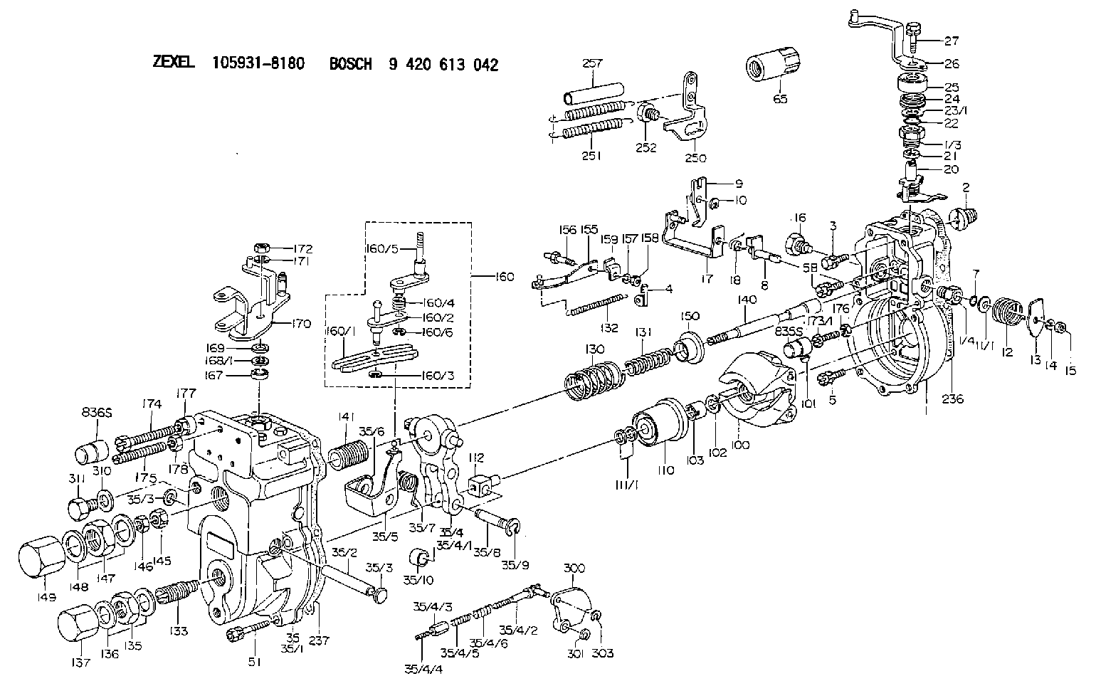
Information governor
BOSCH
9 420 613 042
9420613042
ZEXEL
105931-8180
1059318180
ISUZU
1157705240
1157705240

Rating:
Scheme ###:
| 1. | [1] | 159200-2720 | GOVERNOR HOUSING |
| 1/3. | [1] | 154321-0400 | BUSHING |
| 1/4. | [1] | 154321-0400 | BUSHING |
| 2. | [1] | 154007-0200 | ADAPTOR |
| 3. | [1] | 020018-1840 | BLEEDER SCREW M8P1.25L18 |
| 4. | [1] | 159232-0801 | PLATE |
| 5. | [5] | 029010-6810 | BLEEDER SCREW |
| 5B. | [1] | 020106-1640 | BLEEDER SCREW M6P1.0L14 |
| 7. | [1] | 139710-0200 | O-RING |
| 8. | [1] | 159205-2321 | LEVER SHAFT |
| 9. | [1] | 159202-2300 | CONTROL LEVER |
| 10. | [1] | 016010-0810 | LOCKING WASHER |
| 11/1. | [0] | 029311-0520 | SHIM D20.8&10.3T0.2 |
| 11/1. | [0] | 029311-0530 | SHIM D20.8&10.3T0.25 |
| 11/1. | [0] | 029311-0540 | SHIM D20.8&10.3T0.3 |
| 11/1. | [0] | 029311-0550 | SHIM D20.8&10.3T0.35 |
| 11/1. | [0] | 029311-0560 | SHIM D20.8&10.3T0.4 |
| 11/1. | [0] | 029311-0570 | SHIM D20.8&10.3T0.5 |
| 12. | [1] | 159215-0000 | COILED SPRING |
| 13. | [1] | 159242-0100 | CONTROL LEVER |
| 14. | [1] | 014110-8440 | LOCKING WASHER |
| 15. | [1] | 013020-8040 | UNION NUT M8P1.25H7 |
| 16. | [1] | 159237-0000 | CAPSULE |
| 17. | [1] | 159202-2420 | CONTROL LEVER |
| 18. | [1] | 159215-0300 | COILED SPRING |
| 20. | [1] | 159242-7820 | CONTROL LEVER |
| 21. | [1] | 159242-0600 | BUSHING |
| 22. | [1] | 139710-0300 | O-RING |
| 23/1. | [0] | 029311-0520 | SHIM D20.8&10.3T0.2 |
| 23/1. | [0] | 029311-0530 | SHIM D20.8&10.3T0.25 |
| 23/1. | [0] | 029311-0540 | SHIM D20.8&10.3T0.3 |
| 23/1. | [0] | 029311-0550 | SHIM D20.8&10.3T0.35 |
| 23/1. | [0] | 029311-0560 | SHIM D20.8&10.3T0.4 |
| 23/1. | [0] | 029311-0570 | SHIM D20.8&10.3T0.5 |
| 24. | [1] | 159215-2400 | COILED SPRING |
| 25. | [1] | 154322-0100 | CAP |
| 26. | [1] | 159290-4120 | CONTROL LEVER |
| 27. | [1] | 020006-1640 | BLEEDER SCREW M6P1L16 4T |
| 35. | [1] | 159251-4520 | GOVERNOR COVER |
| 35/1. | [1] | 159201-2410 | GOVERNOR COVER |
| 35/2. | [1] | 159205-0400 | LEVER SHAFT |
| 35/3. | [2] | 159237-0200 | CAPSULE |
| 35/4. | [1] | 159253-0220 | TENSIONING LEVER |
| 35/4/1. | [1] | 159203-0420 | TENSIONING LEVER |
| 35/4/2. | [1] | 159204-5021 | RACK |
| 35/4/3. | [1] | 159233-0300 | UNION NUT |
| 35/4/4. | [1] | 159234-0000 | FLAT-HEAD SCREW |
| 35/4/5. | [1] | 159216-0000 | COILED SPRING |
| 35/4/6. | [1] | 159216-0100 | COILED SPRING |
| 35/5. | [1] | 159203-5320 | GUIDE LEVER |
| 35/6. | [2] | 159235-5000 | BUSHING |
| 35/7. | [1] | 159215-0201 | COILED SPRING |
| 35/8. | [1] | 159231-1300 | BEARING PIN |
| 35/9. | [2] | 016010-0610 | LOCKING WASHER |
| 35/10. | [1] | 159238-1801 | BUSHING |
| 51. | [7] | 020106-3840 | BLEEDER SCREW |
| 65. | [1] | 155404-5700 | CAP |
| 100. | [1] | 154101-0920 | FLYWEIGHT ASSEMBLY |
| 101. | [1] | 025803-1610 | WOODRUFF KEY |
| 102. | [1] | 029321-2020 | LOCKING WASHER |
| 103. | [1] | 029231-2030 | UNION NUT |
| 110. | [1] | 154123-2320 | SLIDING PIECE |
| 111/1. | [0] | 029311-0010 | SHIM D14&10.1T0.2 |
| 111/1. | [0] | 029311-0180 | SHIM D14&10.1T0.3 |
| 111/1. | [0] | 029311-0190 | SHIM D14&10.1T0.40 |
| 111/1. | [0] | 029311-0210 | SHIM D14&10.1T1 |
| 111/1. | [0] | 139410-0000 | SHIM D14.0&10.1T0.5 |
| 111/1. | [0] | 139410-0100 | SHIM D14.0&10.1T1.5 |
| 111/1. | [0] | 139410-3000 | SHIM D14&10.1T2.0 |
| 111/1. | [0] | 139410-3100 | SHIM D14&10.1T3.0 |
| 111/1. | [0] | 139410-3200 | SHIM D14&10.1T4.0 |
| 112. | [1] | 159236-0100 | TERMINAL STUD |
| 130. | [1] | 159210-7800 | GOVERNOR SPRING |
| 131. | [1] | 159211-5000 | GOVERNOR SPRING |
| 132. | [1] | 159214-0000 | COILED SPRING |
| 133. | [1] | 159212-9620 | HEADLESS SCREW |
| 135. | [1] | 139220-0200 | UNION NUT |
| 136. | [2] | 139520-0000 | GASKET |
| 137. | [1] | 159248-0700 | CAP |
| 140. | [1] | 159205-1801 | LEVER SHAFT |
| 141. | [1] | 159234-5200 | GUIDE SLEEVE |
| 145. | [1] | 159233-5000 | UNION NUT |
| 146. | [1] | 023020-8040 | UNION NUT M8P1H5 |
| 147. | [1] | 139222-0200 | UNION NUT |
| 148. | [2] | 139522-0000 | GASKET |
| 149. | [1] | 159237-5000 | CAP |
| 150. | [1] | 159235-5300 | SLOTTED WASHER |
| 155. | [1] | 159204-0320 | STRAP |
| 156. | [1] | 159237-0300 | BLEEDER SCREW |
| 157. | [1] | 014110-5440 | LOCKING WASHER |
| 158. | [1] | 159233-5620 | UNION NUT |
| 159. | [1] | 159242-0800 | PLATE |
| 160. | [1] | 159252-0521 | LEVER GROUP |
| 160/1. | [1] | 159202-1400 | CONTROL LEVER |
| 160/2. | [1] | 159202-1520 | CONTROL LEVER |
| 160/3. | [1] | 016010-0610 | LOCKING WASHER |
| 160/4. | [1] | 159215-1300 | COILED SPRING |
| 160/5. | [1] | 159205-1721 | LEVER SHAFT |
| 160/6. | [1] | 016010-0810 | LOCKING WASHER |
| 167. | [1] | 139610-0600 | PACKING RING |
| 168/1. | [0] | 029311-0640 | SHIM D26.0&10.2T0.95 |
| 168/1. | [0] | 029311-0650 | SHIM D26.0&10.2T0.20 |
| 168/1. | [0] | 029311-0660 | SHIM D26.0&10.2T0.25 |
| 168/1. | [0] | 029311-0670 | SHIM D26.0&10.2T0.30 |
| 168/1. | [0] | 029311-0680 | SHIM D26.0&10.2T0.35 |
| 168/1. | [0] | 029311-0690 | SHIM D26.0&10.2T0.40 |
| 168/1. | [0] | 029311-0700 | SHIM D26.0&10.2T0.50 |
| 168/1. | [0] | 139410-1400 | SHIM D26&10.2T0.7 |
| 168/1. | [0] | 139410-1500 | SHIM D26&10.2T0.9 |
| 168/1. | [0] | 139410-1600 | SHIM D26&10.2T0.8 |
| 168/1. | [0] | 139410-2700 | SHIM D26&10.2T0.6 |
| 169. | [1] | 139410-2300 | SHIM |
| 170. | [1] | 159265-0220 | CONTROL LEVER |
| 171. | [1] | 014110-8440 | LOCKING WASHER |
| 172. | [1] | 013020-8040 | UNION NUT M8P1.25H7 |
| 173/1. | [1] | 139006-3500 | BLEEDER SCREW M6P1.0L33 |
| 173/1. | [1] | 139006-3700 | BLEEDER SCREW M6P1.0L34 |
| 173/1. | [1] | 139006-3800 | BLEEDER SCREW M6P1.0L35 |
| 173/1. | [1] | 139006-3900 | BLEEDER SCREW M6P1.0L36 |
| 173/1. | [1] | 139006-5300 | BLEEDER SCREW M6P1.0L31 |
| 173/1. | [1] | 139006-5400 | BLEEDER SCREW M6P1.0L32 |
| 173/1. | [1] | 155615-2500 | BLEEDER SCREW M6P1.0L37 |
| 174. | [1] | 154010-8000 | BLEEDER SCREW |
| 175. | [1] | 154010-8100 | BLEEDER SCREW M8P1.25L65 |
| 176. | [1] | 159225-8600 | UNION NUT |
| 177. | [1] | 154011-2300 | UNION NUT |
| 178. | [1] | 154011-0100 | HEXAGON NUT |
| 236. | [1] | 154390-0000 | GASKET |
| 237. | [1] | 154390-1100 | GASKET |
| 250. | [1] | 159220-0520 | BRACKET |
| 251. | [2] | 154332-2400 | COILED SPRING |
| 252. | [1] | 159248-0200 | BLEEDER SCREW |
| 257. | [2] | 154156-1800 | TUBE |
| 300. | [1] | 159282-7100 | CAM PLATE |
| 301. | [1] | 016010-0840 | LOCKING WASHER |
| 303. | [1] | 016010-0540 | LOCKING WASHER |
| 310. | [1] | 139516-0100 | GASKET |
| 311. | [1] | 159237-0100 | CAPSULE |
| 835S. | [1] | 154062-1900 | CAP D12L24 |
| 836S. | [1] | 154062-1700 | CAP D20L32 |
Include in #1:
101603-7630
as GOVERNOR
Cross reference number
Zexel num
Bosch num
Firm num
Name
Information:
Stopping the engine immediately after it has been working under load can result in overheating and accelerated wear of the engine components. Allow the engine to cool down before stopping. Avoiding hot engine shutdowns will maximize turbocharger shaft and bearing life.
Emergency Stopping
Emergency shutoff controls are for EMERGENCY use ONLY. DO NOT use Emergency shutoff devices or controls for normal stopping procedure.
Make sure that any external system components that have been operating to support engine operation are secured after any stop.Emergency Stop Buttons
Emergency Stop Button, shown mounted on a junction box.Emergency stops may be made by pushing the Emergency Stop Button located on the junction box (if equipped). Both the Button and the air inlet shutoff (if equipped) require resetting before the engine will start.
Control Panel Emergency Stop Button.If equipped with the EMCPII Control Panel, press the Emergency Stop Button for an emergency stop. The ECS must be reset before resuming operation. Move the ECS to the OFF/RESET position. The ECS can also be used to shut the engine off in an emergency. Move the ECS to the OFF/RESET position. The engine will immediately shut off.Manual Stopping
A manual shutoff shaft is provided to override the governor control. The shaft will move the fuel control linkage to the FUEL OFF position. Refer to the Model Views for the engine location of the shaft. The engine may be stopped by using the shaft and the Woodward Actuator (if equipped) or the Mechanical Governor (if equipped).
Typical Woodward Actuator Control Lever.If equipped with a Woodward Actuator, move the control lever to the FUEL OFF position.
Typical Mechanical Governor ControlIf equipped with a Mechanical Governor Control, move the control to the FUEL OFF position.Hold the lever at the FUEL OFF position until the engine stops.Air Shutoff (If Equipped)
Some engines are equipped with an air shutoff, located between the aftercooler and the turbocharger. If equipped with an air shutoff lever, move the lever to the OFF position.Manual Stop Procedure
There may be several ways to shut off your engine. Make sure the shutoff procedures are understood. Use the following general guidelines for stopping the engine.EPG Engines
If the ECS is in the AUTO position and the remote contact opens, the engine will run for a pre-programmed cool down period. This will only occur when the cool down mode is used. If the cool down mode is not used, the engine will shut off immediately.
If the ECS is in the AUTO position, the remote contact opens, and the cool down time expires, the CTR will be unlatched and the starting motors may be re-engaged.1. Open the main electrical circuit breaker to remove the load.2. The engine should be run for a cool down period before being shut off. This can be accomplished with the COOLDOWN STOP switch, or the operator can control the cool down and shut off.
To use the COOLDOWN/STOP switch, turn the ECS to the COOLDOWN/STOP position. The engine will operate for a pre-programmed time period. The timer will active the fuel shutoff after the cool down.Alternatively,