Information governor
BOSCH
9 420 613 040
9420613040
ZEXEL
105931-8062
1059318062
ISUZU
8970468150
8970468150

Rating:
Scheme ###:
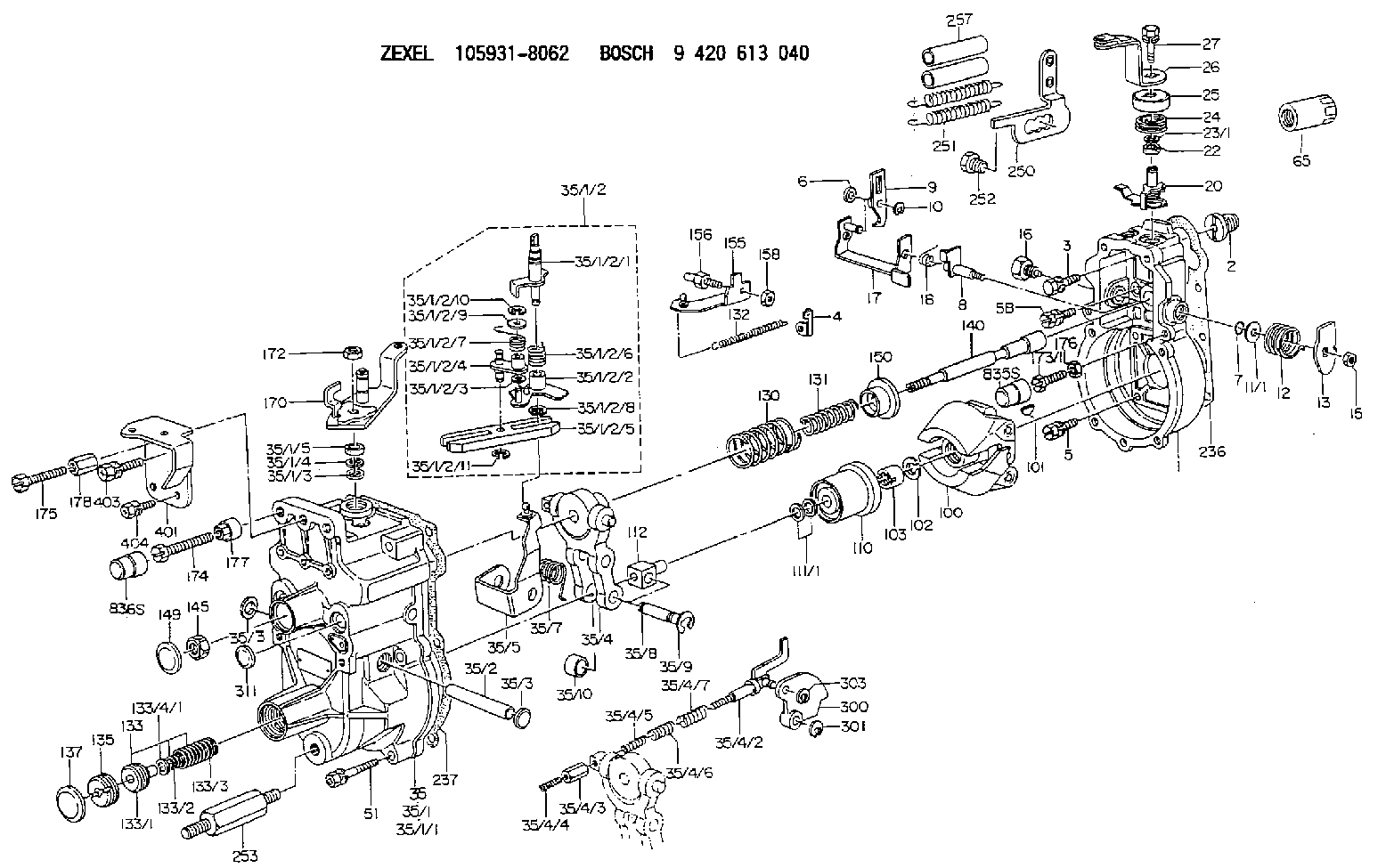
| 1. | [1] | 159200-7120 | GOVERNOR HOUSING |
| 2. | [1] | 154007-0200 | ADAPTOR |
| 3. | [1] | 020018-1840 | BLEEDER SCREW M8P1.25L18 |
| 4. | [1] | 159232-1600 | PLATE |
| 5. | [5] | 029010-6810 | BLEEDER SCREW |
| 5B. | [1] | 020106-1640 | BLEEDER SCREW M6P1.0L14 |
| 6. | [1] | 159242-0600 | BUSHING |
| 7. | [1] | 139710-0200 | O-RING |
| 8. | [1] | 159205-2321 | LEVER SHAFT |
| 9. | [1] | 159202-5601 | CONTROL LEVER |
| 10. | [1] | 016010-0810 | LOCKING WASHER |
| 11/1. | [0] | 029311-0220 | SHIM D18&10.3T0.2 |
| 11/1. | [0] | 029311-0230 | SHIM D18&10.3T0.5 |
| 11/1. | [0] | 029311-0430 | SHIM D18&10.3T0.30 |
| 11/1. | [0] | 029311-0440 | SHIM D18&10.3T0.40 |
| 11/1. | [0] | 029311-0450 | SHIM D18&10.3T0.25 |
| 11/1. | [0] | 029311-0460 | SHIM D18&10.3T0.35 |
| 11/1. | [0] | 139410-3300 | SHIM D18&10.3T0.6 |
| 11/1. | [0] | 139410-3400 | SHIM D18&10.3T0.8 |
| 11/1. | [0] | 139410-3500 | SHIM D18&10.3T0.9 |
| 12. | [1] | 159215-0000 | COILED SPRING |
| 13. | [1] | 159242-6601 | CONTROL LEVER |
| 15. | [1] | 013020-8040 | UNION NUT M8P1.25H7 |
| 16. | [1] | 159237-5500 | CAPSULE |
| 17. | [1] | 159202-5320 | CONTROL LEVER |
| 18. | [1] | 159215-0300 | COILED SPRING |
| 20. | [1] | 159242-7120 | CONTROL LEVER |
| 22. | [1] | 139610-0700 | PACKING RING |
| 23/1. | [0] | 139411-0700 | SHIM D22&11T0.7 |
| 23/1. | [0] | 153305-0100 | SHIM D22&11T0.5 |
| 23/1. | [0] | 153305-0200 | SHIM D22&11T0.4 |
| 23/1. | [0] | 153305-0300 | SHIM D22&11T0.3 |
| 23/1. | [0] | 153305-0400 | SHIM D22&11T0.25 |
| 23/1. | [0] | 153305-0500 | SHIM D22&11T1.0 |
| 23/1. | [0] | 153305-0600 | SHIM D22&11T1.1 |
| 23/1. | [0] | 153305-0700 | SHIM D22&11T2.0 |
| 23/1. | [0] | 153305-1300 | SHIM D22&11T0.951 |
| 23/1. | [0] | 153305-1400 | SHIM D22&11T0.95 |
| 24. | [1] | 159215-2000 | COILED SPRING |
| 25. | [1] | 159235-5800 | CAP |
| 26. | [1] | 159290-2920 | CONTROL LEVER |
| 27. | [1] | 020006-1640 | BLEEDER SCREW M6P1L16 4T |
| 35. | [1] | 159250-3920 | GOVERNOR COVER |
| 35/1. | [1] | 159301-0520 | GOVERNOR COVER |
| 35/1/1. | [1] | 159301-0620 | GOVERNOR COVER |
| 35/1/2. | [1] | 159252-2820 | LEVER GROUP |
| 35/1/2/1. | [1] | 159205-4520 | LEVER SHAFT |
| 35/1/2/2. | [1] | 159202-4810 | CONTROL LEVER |
| 35/1/2/3. | [1] | 029310-6030 | SHIM D11.5&6.2T0.2 |
| 35/1/2/4. | [1] | 159202-4520 | CONTROL LEVER |
| 35/1/2/5. | [1] | 159202-2200 | CONTROL LEVER |
| 35/1/2/6. | [1] | 159215-2301 | COILED SPRING |
| 35/1/2/7. | [1] | 159215-3900 | COILED SPRING |
| 35/1/2/8. | [1] | 016010-0810 | LOCKING WASHER |
| 35/1/2/9. | [1] | 014020-6140 | PLAIN WASHER |
| 35/1/2/10. | [1] | 016010-0610 | LOCKING WASHER |
| 35/1/2/11. | [1] | 016010-0810 | LOCKING WASHER |
| 35/1/3. | [1] | 139411-0600 | SHIM |
| 35/1/4. | [1] | 159238-3000 | LOCKING WASHER |
| 35/1/5. | [1] | 139610-0800 | PACKING RING |
| 35/2. | [1] | 159205-0400 | LEVER SHAFT |
| 35/3. | [2] | 159237-0200 | CAPSULE |
| 35/3. | [2] | 159237-0200 | CAPSULE |
| 35/4. | [1] | 159253-2720 | TENSIONING LEVER |
| 35/4/2. | [1] | 159204-6022 | RACK |
| 35/4/3. | [1] | 159233-0300 | UNION NUT |
| 35/4/4. | [1] | 159234-0300 | FLAT-HEAD SCREW |
| 35/4/5. | [1] | 159216-0000 | COILED SPRING |
| 35/4/6. | [1] | 159216-0100 | COILED SPRING |
| 35/4/7. | [1] | 159216-0700 | COILED SPRING |
| 35/5. | [1] | 159203-6120 | GUIDE LEVER |
| 35/7. | [1] | 159215-1701 | COILED SPRING |
| 35/8. | [1] | 159231-1300 | BEARING PIN |
| 35/9. | [2] | 016010-0610 | LOCKING WASHER |
| 35/10. | [1] | 159238-2900 | BUSHING |
| 51. | [7] | 020106-3840 | BLEEDER SCREW |
| 65. | [1] | 155404-5700 | CAP |
| 100. | [1] | 154101-0420 | FLYWEIGHT ASSEMBLY |
| 101. | [1] | 025803-1610 | WOODRUFF KEY |
| 102. | [1] | 029321-2020 | LOCKING WASHER |
| 103. | [1] | 029231-2030 | UNION NUT |
| 110. | [1] | 154123-2320 | SLIDING PIECE |
| 111/1. | [0] | 029311-0010 | SHIM D14&10.1T0.2 |
| 111/1. | [0] | 029311-0180 | SHIM D14&10.1T0.3 |
| 111/1. | [0] | 029311-0190 | SHIM D14&10.1T0.40 |
| 111/1. | [0] | 029311-0210 | SHIM D14&10.1T1 |
| 111/1. | [0] | 139410-0000 | SHIM D14.0&10.1T0.5 |
| 111/1. | [0] | 139410-0100 | SHIM D14.0&10.1T1.5 |
| 111/1. | [0] | 139410-3000 | SHIM D14&10.1T2.0 |
| 111/1. | [0] | 139410-3100 | SHIM D14&10.1T3.0 |
| 111/1. | [0] | 139410-3200 | SHIM D14&10.1T4.0 |
| 112. | [1] | 159236-0200 | TERMINAL STUD |
| 130. | [1] | 159210-1400 | GOVERNOR SPRING |
| 131. | [1] | 159211-1100 | GOVERNOR SPRING |
| 132. | [1] | 159214-0200 | COILED SPRING |
| 133. | [1] | 159212-3320 | SPRING PACK |
| 133/1. | [1] | 159234-5602 | GUIDE SLEEVE |
| 133/2. | [1] | 159212-3300 | COILED SPRING |
| 133/3. | [1] | 159212-3400 | COILED SPRING |
| 133/4/1. | [0] | 029310-9240 | SHIM D11.9&9T0.1 |
| 133/4/1. | [0] | 029310-9250 | SHIM D11.9&9T0.2 |
| 133/4/1. | [0] | 029310-9260 | SHIM D11.9&9T0.25 |
| 133/4/1. | [0] | 029310-9270 | SHIM D11.9&9T1.0 |
| 133/4/1. | [0] | 139409-0100 | SHIM D11.9&9T0.3 |
| 133/4/1. | [0] | 139409-0200 | SHIM D11.9&9T0.5 |
| 133/4/1. | [0] | 139409-0300 | SHIM D11.5&9T0.8 |
| 135. | [1] | 159248-2700 | FLAT-HEAD SCREW |
| 137. | [1] | 159237-5300 | CAPSULE |
| 140. | [1] | 159205-2101 | LEVER SHAFT |
| 145. | [1] | 159233-5700 | UNION NUT |
| 149. | [1] | 159237-5400 | CAPSULE |
| 150. | [1] | 159235-5300 | SLOTTED WASHER |
| 155. | [1] | 159204-5920 | STRAP |
| 156. | [1] | 159233-6020 | BLEEDER SCREW |
| 158. | [1] | 013020-5240 | UNION NUT M5P0.8H4 |
| 170. | [1] | 159263-7021 | CONTROL LEVER |
| 172. | [1] | 013020-8040 | UNION NUT M8P1.25H7 |
| 173/1. | [1] | 139006-3500 | BLEEDER SCREW M6P1.0L33 |
| 173/1. | [1] | 139006-3700 | BLEEDER SCREW M6P1.0L34 |
| 173/1. | [1] | 139006-3800 | BLEEDER SCREW M6P1.0L35 |
| 173/1. | [1] | 139006-3900 | BLEEDER SCREW M6P1.0L36 |
| 173/1. | [1] | 139006-5300 | BLEEDER SCREW M6P1.0L31 |
| 173/1. | [1] | 139006-5400 | BLEEDER SCREW M6P1.0L32 |
| 173/1. | [1] | 155615-2500 | BLEEDER SCREW M6P1.0L37 |
| 174. | [1] | 154010-8100 | BLEEDER SCREW M8P1.25L65 |
| 174B. | [1] | 154010-7200 | BLEEDER SCREW M8P1.25L62 |
| 175. | [1] | 154012-4700 | BLEEDER SCREW |
| 176. | [1] | 159225-8600 | UNION NUT |
| 177. | [1] | 154011-2300 | UNION NUT |
| 178. | [1] | 154011-3500 | UNION NUT |
| 236. | [1] | 154390-0000 | GASKET |
| 237. | [1] | 159238-3100 | GASKET |
| 250. | [1] | 159228-4920 | BRACKET |
| 251. | [2] | 154317-9900 | COILED SPRING |
| 252. | [1] | 159248-0200 | BLEEDER SCREW |
| 253. | [1] | 159248-0401 | BLEEDER SCREW |
| 257. | [2] | 154156-0500 | TUBE |
| 300. | [1] | 159283-2000 | CAM PLATE |
| 301. | [1] | 016010-0840 | LOCKING WASHER |
| 303. | [1] | 016010-0540 | LOCKING WASHER |
| 311. | [1] | 159237-0200 | CAPSULE |
| 401. | [1] | 159229-6921 | BRACKET |
| 403. | [1] | 020118-1640 | BLEEDER SCREW |
| 404. | [2] | 020106-1240 | BLEEDER SCREW M6P1.0L12 |
Cross reference number
Zexel num
Bosch num
Firm num
Name
105931-8062
9 420 613 040
8970468150 ISUZU
GOVERNOR
* K
* K
Information:
You must read and understand the warnings and instructions contained in the Safety section of this manual before performing any operation or maintenance procedures.Before proceeding with this maintenance interval, perform previous maintenance interval requirements. Perform the maintenance at the interval listed in the Maintenance Schedule for your engine.Engine Protection Controls
Inspect For Proper Operation
The engine protective alarm and shutoff controls must be tested, inspected and checked by an authorized Caterpillar dealer at least every year or 1000 hours for proper operation. The manual shutoff functions should be tested to ensure proper operation and protection to the engine. Refer to Engine Control, Monitoring and Protection in the Operation Section in this Manual. Have the checks made by a qualified mechanic. Consult your authorized Caterpillar engine dealer, or refer to the Service Manual for your engine. Check Alarm and Shutdown Settings
Check for loose, broken, or damaged wiring or components. Check the condition of all sensors and wiring. Repair or replace any broken or malfunctioning sensors before they become a problem. The inspection only takes a few minutes and could avert a potential problem that could cause your engine to fail. Check GSC Display Window Readings
Refer to the operating parameters in the Engine Control, Monitoring and Protection topic.While operating, observe all GSC display window readings hourly, especially the engine oil pressure, fuel pressure and coolant temperature.Operational Checks
Start the engine. Use the starting procedure found in the Engine Starting topic in this publication.The operational checks are intended to check the engine starting and stopping, lubrication and fuel systems as well as overall operation. The checks should take no longer than five minutes to complete. Longer periods of operation are not required. A more thorough Performance Analysis should be performed with the engine operating under load.Automatic Switches
Check that all switches are in proper position for automatic start. The shutoff controls must be checked so that they function properly when they are required. To prevent damage to the engine while performing the test, only authorized personnel or your Caterpillar dealer should perform the checks.SR4 Generator
Make sure residual voltage in the rotor, stator and the generator is discharged.If this generator is to be connected to a utility electrical distribution system, it must be isolated from the distribution system by means of:a. Opening the main switch in the case of the generator temporarily connected to the system or,b. A double throw (transfer) switch in the case of a permanent connection to the system.Failure to do so could result in personal injury or death due to electrical shock. This warning does not apply when a generator and utility distribution system are designed and approved by the utility to run in parallel.
Before working inside the generator, make sure that the starting motor can not be activated by any automatic or manual signal.Electronic components in the regulator can be damaged during generator operation if contact is made between the part and ground.
Check Winding Insulation Resistance
When the engine-generator is operating, voltages up to 600V are present in these areas near
Have questions with 105931-8062?
Group cross 105931-8062 ZEXEL
Isuzu
Isuzu
105931-8062
9 420 613 040
8970468150
GOVERNOR