Information governor
BOSCH
9 420 613 012
9420613012
ZEXEL
105931-8060
1059318060
ISUZU
8970323660
8970323660
Rating:
Scheme ###:
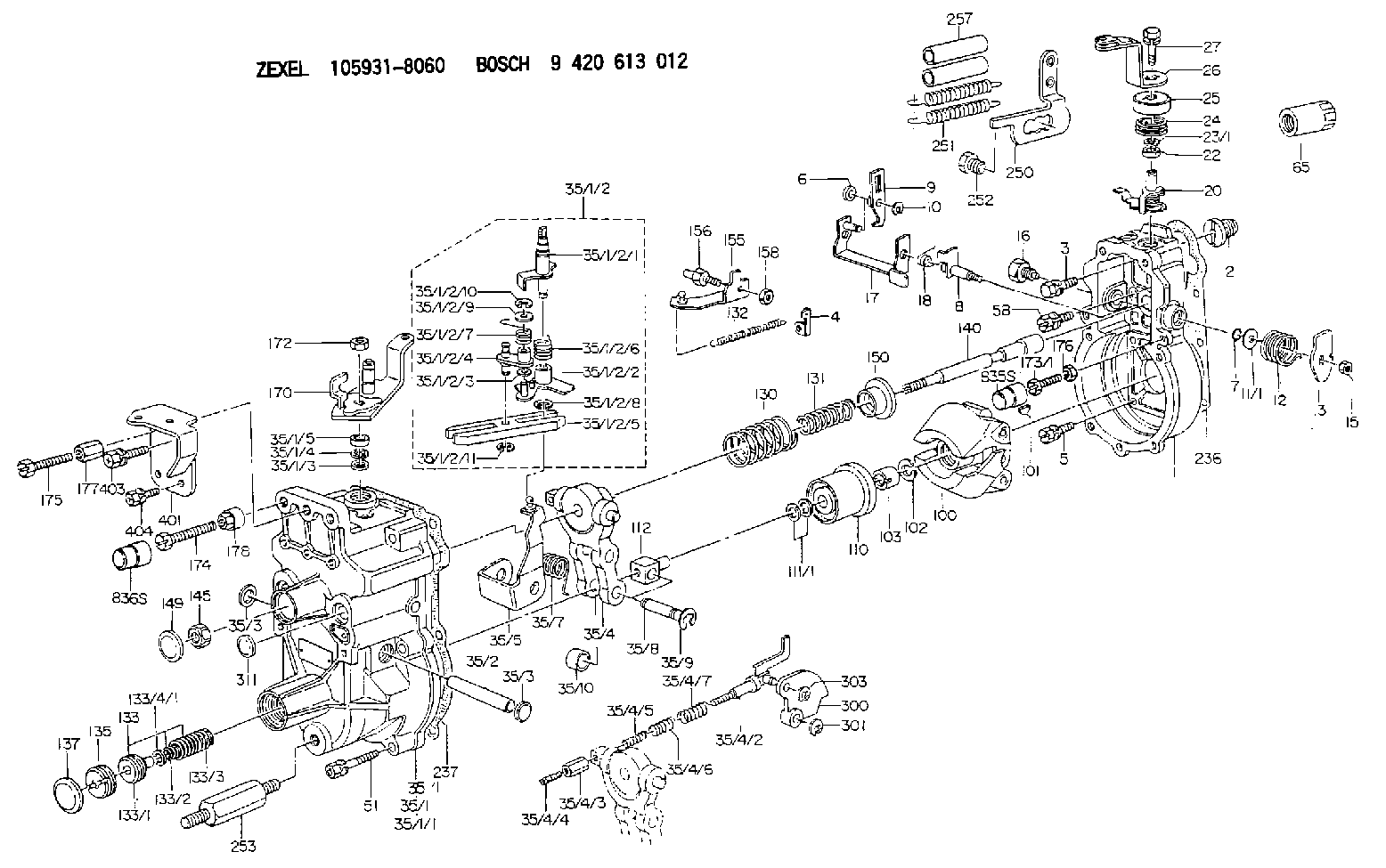
| 1. | [1] | 159200-7120 | GOVERNOR HOUSING |
| 2. | [1] | 154007-0200 | ADAPTOR |
| 3. | [1] | 020018-1840 | BLEEDER SCREW M8P1.25L18 |
| 4. | [1] | 159232-1600 | PLATE |
| 5. | [5] | 029010-6810 | BLEEDER SCREW |
| 5B. | [1] | 020106-1640 | BLEEDER SCREW M6P1.0L14 |
| 6. | [1] | 159242-0600 | BUSHING |
| 7. | [1] | 139710-0200 | O-RING |
| 8. | [1] | 159205-2321 | LEVER SHAFT |
| 9. | [1] | 159202-5601 | CONTROL LEVER |
| 10. | [1] | 016010-0810 | LOCKING WASHER |
| 11/1. | [0] | 029311-0220 | SHIM D18&10.3T0.2 |
| 11/1. | [0] | 029311-0230 | SHIM D18&10.3T0.5 |
| 11/1. | [0] | 029311-0430 | SHIM D18&10.3T0.30 |
| 11/1. | [0] | 029311-0440 | SHIM D18&10.3T0.40 |
| 11/1. | [0] | 029311-0450 | SHIM D18&10.3T0.25 |
| 11/1. | [0] | 029311-0460 | SHIM D18&10.3T0.35 |
| 11/1. | [0] | 139410-3300 | SHIM D18&10.3T0.6 |
| 11/1. | [0] | 139410-3400 | SHIM D18&10.3T0.8 |
| 11/1. | [0] | 139410-3500 | SHIM D18&10.3T0.9 |
| 12. | [1] | 159215-0000 | COILED SPRING |
| 13. | [1] | 159242-6601 | CONTROL LEVER |
| 15. | [1] | 013020-8040 | UNION NUT M8P1.25H7 |
| 16. | [1] | 159237-5500 | CAPSULE |
| 17. | [1] | 159202-5320 | CONTROL LEVER |
| 18. | [1] | 159215-0300 | COILED SPRING |
| 20. | [1] | 159242-7120 | CONTROL LEVER |
| 22. | [1] | 139610-0700 | PACKING RING |
| 23/1. | [0] | 139411-0700 | SHIM D22&11T0.7 |
| 23/1. | [0] | 153305-0100 | SHIM D22&11T0.5 |
| 23/1. | [0] | 153305-0200 | SHIM D22&11T0.4 |
| 23/1. | [0] | 153305-0300 | SHIM D22&11T0.3 |
| 23/1. | [0] | 153305-0400 | SHIM D22&11T0.25 |
| 23/1. | [0] | 153305-0500 | SHIM D22&11T1.0 |
| 23/1. | [0] | 153305-0600 | SHIM D22&11T1.1 |
| 23/1. | [0] | 153305-0700 | SHIM D22&11T2.0 |
| 23/1. | [0] | 153305-1300 | SHIM D22&11T0.951 |
| 23/1. | [0] | 153305-1400 | SHIM D22&11T0.95 |
| 24. | [1] | 159215-2000 | COILED SPRING |
| 25. | [1] | 159235-5800 | CAP |
| 26. | [1] | 159290-2920 | CONTROL LEVER |
| 27. | [1] | 020006-1640 | BLEEDER SCREW M6P1L16 4T |
| 35. | [1] | 159250-3920 | GOVERNOR COVER |
| 35/1. | [1] | 159301-0520 | GOVERNOR COVER |
| 35/1/1. | [1] | 159301-0620 | GOVERNOR COVER |
| 35/1/2. | [1] | 159252-2820 | LEVER GROUP |
| 35/1/2/1. | [1] | 159205-4520 | LEVER SHAFT |
| 35/1/2/2. | [1] | 159202-4810 | CONTROL LEVER |
| 35/1/2/3. | [1] | 029310-6030 | SHIM D11.5&6.2T0.2 |
| 35/1/2/4. | [1] | 159202-4520 | CONTROL LEVER |
| 35/1/2/5. | [1] | 159202-2200 | CONTROL LEVER |
| 35/1/2/6. | [1] | 159215-2301 | COILED SPRING |
| 35/1/2/7. | [1] | 159215-3900 | COILED SPRING |
| 35/1/2/8. | [1] | 016010-0810 | LOCKING WASHER |
| 35/1/2/9. | [1] | 014020-6140 | PLAIN WASHER |
| 35/1/2/10. | [1] | 016010-0610 | LOCKING WASHER |
| 35/1/2/11. | [1] | 016010-0810 | LOCKING WASHER |
| 35/1/3. | [1] | 139411-0600 | SHIM |
| 35/1/4. | [1] | 159238-3000 | LOCKING WASHER |
| 35/1/5. | [1] | 139610-0800 | PACKING RING |
| 35/2. | [1] | 159205-0400 | LEVER SHAFT |
| 35/3. | [2] | 159237-0200 | CAPSULE |
| 35/3. | [2] | 159237-0200 | CAPSULE |
| 35/4. | [1] | 159253-2720 | TENSIONING LEVER |
| 35/4/2. | [1] | 159204-6022 | RACK |
| 35/4/3. | [1] | 159233-0300 | UNION NUT |
| 35/4/4. | [1] | 159234-0300 | FLAT-HEAD SCREW |
| 35/4/5. | [1] | 159216-0000 | COILED SPRING |
| 35/4/6. | [1] | 159216-0100 | COILED SPRING |
| 35/4/7. | [1] | 159216-0700 | COILED SPRING |
| 35/5. | [1] | 159203-6120 | GUIDE LEVER |
| 35/7. | [1] | 159215-1701 | COILED SPRING |
| 35/8. | [1] | 159231-1300 | BEARING PIN |
| 35/9. | [2] | 016010-0610 | LOCKING WASHER |
| 35/10. | [1] | 159238-2900 | BUSHING |
| 51. | [7] | 020106-3840 | BLEEDER SCREW |
| 65. | [1] | 155404-5700 | CAP |
| 100. | [1] | 154101-0420 | FLYWEIGHT ASSEMBLY |
| 101. | [1] | 025803-1610 | WOODRUFF KEY |
| 102. | [1] | 029321-2020 | LOCKING WASHER |
| 103. | [1] | 029231-2030 | UNION NUT |
| 110. | [1] | 154123-2320 | SLIDING PIECE |
| 111/1. | [0] | 029311-0010 | SHIM D14&10.1T0.2 |
| 111/1. | [0] | 029311-0180 | SHIM D14&10.1T0.3 |
| 111/1. | [0] | 029311-0190 | SHIM D14&10.1T0.40 |
| 111/1. | [0] | 029311-0210 | SHIM D14&10.1T1 |
| 111/1. | [0] | 139410-0000 | SHIM D14.0&10.1T0.5 |
| 111/1. | [0] | 139410-0100 | SHIM D14.0&10.1T1.5 |
| 111/1. | [0] | 139410-3000 | SHIM D14&10.1T2.0 |
| 111/1. | [0] | 139410-3100 | SHIM D14&10.1T3.0 |
| 111/1. | [0] | 139410-3200 | SHIM D14&10.1T4.0 |
| 112. | [1] | 159236-0200 | TERMINAL STUD |
| 130. | [1] | 159210-1000 | GOVERNOR SPRING |
| 131. | [1] | 159211-3000 | GOVERNOR SPRING |
| 132. | [1] | 159214-0200 | COILED SPRING |
| 133. | [1] | 159212-3320 | SPRING PACK |
| 133/1. | [1] | 159234-5602 | GUIDE SLEEVE |
| 133/2. | [1] | 159212-3300 | COILED SPRING |
| 133/3. | [1] | 159212-3400 | COILED SPRING |
| 133/4/1. | [0] | 029310-9240 | SHIM D11.9&9T0.1 |
| 133/4/1. | [0] | 029310-9250 | SHIM D11.9&9T0.2 |
| 133/4/1. | [0] | 029310-9260 | SHIM D11.9&9T0.25 |
| 133/4/1. | [0] | 029310-9270 | SHIM D11.9&9T1.0 |
| 133/4/1. | [0] | 139409-0100 | SHIM D11.9&9T0.3 |
| 133/4/1. | [0] | 139409-0200 | SHIM D11.9&9T0.5 |
| 133/4/1. | [0] | 139409-0300 | SHIM D11.5&9T0.8 |
| 135. | [1] | 159248-2700 | FLAT-HEAD SCREW |
| 137. | [1] | 159237-5300 | CAPSULE |
| 140. | [1] | 159205-2101 | LEVER SHAFT |
| 145. | [1] | 159233-5700 | UNION NUT |
| 149. | [1] | 159237-5400 | CAPSULE |
| 150. | [1] | 159235-5300 | SLOTTED WASHER |
| 155. | [1] | 159204-5920 | STRAP |
| 156. | [1] | 159233-6020 | BLEEDER SCREW |
| 158. | [1] | 013020-5240 | UNION NUT M5P0.8H4 |
| 170. | [1] | 159263-7020 | CONTROL LEVER |
| 172. | [1] | 013020-8040 | UNION NUT M8P1.25H7 |
| 173/1. | [1] | 139006-3500 | BLEEDER SCREW M6P1.0L33 |
| 173/1. | [1] | 139006-3700 | BLEEDER SCREW M6P1.0L34 |
| 173/1. | [1] | 139006-3800 | BLEEDER SCREW M6P1.0L35 |
| 173/1. | [1] | 139006-3900 | BLEEDER SCREW M6P1.0L36 |
| 173/1. | [1] | 139006-5300 | BLEEDER SCREW M6P1.0L31 |
| 173/1. | [1] | 139006-5400 | BLEEDER SCREW M6P1.0L32 |
| 173/1. | [1] | 155615-2500 | BLEEDER SCREW M6P1.0L37 |
| 174. | [1] | 154010-8100 | BLEEDER SCREW M8P1.25L65 |
| 174B. | [1] | 154010-7200 | BLEEDER SCREW M8P1.25L62 |
| 175. | [1] | 154012-4700 | BLEEDER SCREW |
| 176. | [1] | 159225-8600 | UNION NUT |
| 177. | [1] | 154011-2300 | UNION NUT |
| 178. | [1] | 154011-3500 | UNION NUT |
| 236. | [1] | 154390-0000 | GASKET |
| 237. | [1] | 159238-3100 | GASKET |
| 250. | [1] | 159228-4920 | BRACKET |
| 251. | [2] | 154317-9900 | COILED SPRING |
| 252. | [1] | 159248-0200 | BLEEDER SCREW |
| 253. | [1] | 159248-0401 | BLEEDER SCREW |
| 257. | [2] | 154156-0500 | TUBE |
| 300. | [1] | 159282-4400 | CAM PLATE |
| 301. | [1] | 016010-0840 | LOCKING WASHER |
| 303. | [1] | 016010-0540 | LOCKING WASHER |
| 311. | [1] | 159237-0200 | CAPSULE |
| 401. | [1] | 159229-6920 | BRACKET |
| 403. | [1] | 020118-1640 | BLEEDER SCREW |
| 404. | [2] | 020106-1240 | BLEEDER SCREW M6P1.0L12 |
| 835S. | [1] | 154062-1900 | CAP D12L24 |
| 836S. | [1] | 154062-1700 | CAP D20L32 |
Cross reference number
Zexel num
Bosch num
Firm num
Name
Information:
Air Cleaner Indicator
This engine is equipped with an air cleaner mounted service indicator. A colored piston showing in the window indicates the need for servicing the air cleaner. Observe the air cleaner service indicator at regular scheduled intervals. Clean or replace the air cleaner element when the yellow diaphragm enters the red zone or the red piston locks in the visible position.If your air cleaner element becomes plugged, the air can split the element filter material. Unfiltered air will drastically accelerate internal engine wear. Excessive exhaust smoke and/or loss of power may indicate a need for air cleaner element inspection. Perform maintenance on the air cleaner as instructed in this topic.Keep spare filter elements on hand for replacement. The element should be thoroughly checked for rips or tears in the filter material, seal/gasket damage and replaced at least every year or 250 hours.Test Service Indicator
Air cleaner indicators are inexpensive but important instruments which function to show air filter element restriction as the element is progressively filled (plugged) with dust. In average dust conditions, the air cleaner indicators should be tested for proper operation Every 250 Hours . If dust is severe, the indicator should be checked Daily. To test the indicator, perform the following checks.* Check for ease of resetting; should reset in less than a maximum of three pushes.* Check the movement of the yellow core when the engine is accelerated to rated engine speed. The yellow core should latch at or very close to the highest vacuum obtained.If the indicator will NOT reset easily, or the yellow core will not latch at highest vacuum, the indicator(s) should be replaced. If the new indicator will not reset, the indicator sensor hole may be plugged.THE INDICATOR SHOULD BE REPLACED AT OVERHAUL AND/OR MAJOR ENGINE COMPONENT REPLACEMENT. THE INDICATOR MUST BE REPLACED EVERY YEAR REGARDLESS OF OPERATING CONDITIONS. When installing a new indicator, excessive tightening force may crack the top of the indicator. Tighten the indicator to a torque value of 2 N m (18 lb in). Contact your Caterpillar dealer for parts and/or assistance. Clean/Replace Air Cleaner Elements
Never service the air cleaner with the engine running since this will allow dirt to enter the engine. Check the inlet piping for leaks. Make all repairs to inlet piping immediately, as dirt and debris could enter the engine causing damage to the turbocharger and engine components.Clean or replace elements using these recommendations and/or your weather and operating conditions, or when required by the restriction indicator.
1. Remove air cleaner cover and element. Clean or discard used element. Refer to SEBF8062, Guideline for Reusable Parts-Cleaning and Inspection of Air Filters. 2. Cover air inlet opening with a clean cloth or towel to prevent dirt and debris from entering the engine. 3. Clean the inside of the air cleaner cover and body. 4. Remove cloth from air inlet opening and install clean element while noting arrows indicating air flow on the side of the element. 5. Install cover and reset service indicator.Cleaning