Information governor
BOSCH
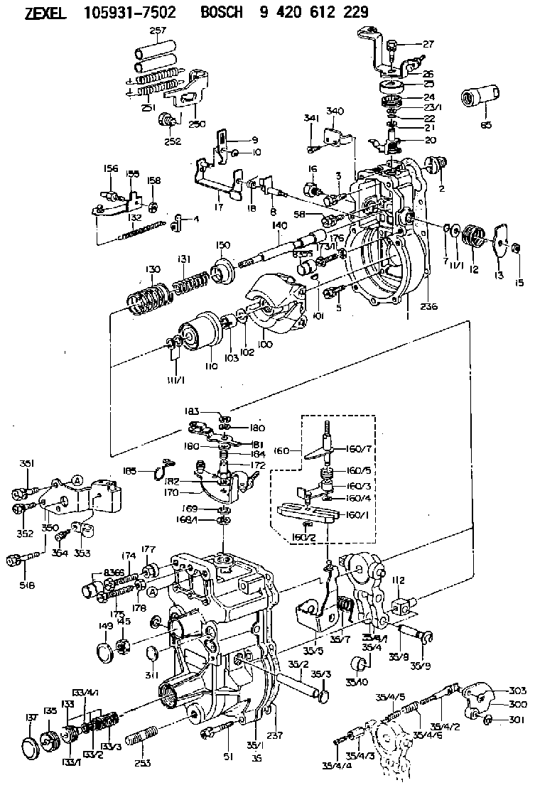
9 420 612 229
9420612229
ZEXEL
105931-7502
1059317502
MITSUBISHI
ME730278
me730278
Rating:
Scheme ###:
| 1. | [1] | 159200-4220 | GOVERNOR HOUSING |
| 2. | [1] | 154007-0200 | ADAPTOR |
| 3. | [1] | 020018-1840 | BLEEDER SCREW M8P1.25L18 |
| 4. | [1] | 159232-0201 | PLATE |
| 5. | [5] | 029010-6810 | BLEEDER SCREW |
| 5B. | [1] | 020106-1640 | BLEEDER SCREW M6P1.0L14 |
| 7. | [1] | 016530-1010 | O-RING |
| 8. | [1] | 159205-2321 | LEVER SHAFT |
| 9. | [1] | 159202-5101 | CONTROL LEVER |
| 10. | [1] | 016010-0810 | LOCKING WASHER |
| 11/1. | [0] | 029311-0220 | SHIM D18&10.3T0.2 |
| 11/1. | [0] | 029311-0230 | SHIM D18&10.3T0.5 |
| 11/1. | [0] | 029311-0430 | SHIM D18&10.3T0.30 |
| 11/1. | [0] | 029311-0440 | SHIM D18&10.3T0.40 |
| 11/1. | [0] | 029311-0450 | SHIM D18&10.3T0.25 |
| 11/1. | [0] | 029311-0460 | SHIM D18&10.3T0.35 |
| 11/1. | [0] | 139410-3300 | SHIM D18&10.3T0.6 |
| 11/1. | [0] | 139410-3400 | SHIM D18&10.3T0.8 |
| 11/1. | [0] | 139410-3500 | SHIM D18&10.3T0.9 |
| 12. | [1] | 159215-0000 | COILED SPRING |
| 13. | [1] | 159242-6601 | CONTROL LEVER |
| 15. | [1] | 013020-8040 | UNION NUT M8P1.25H7 |
| 16. | [1] | 159237-5500 | CAPSULE |
| 17. | [1] | 159202-5320 | CONTROL LEVER |
| 18. | [1] | 159215-0300 | COILED SPRING |
| 20. | [1] | 159242-0220 | CONTROL LEVER |
| 21. | [1] | 159242-0600 | BUSHING |
| 22. | [1] | 016530-1010 | O-RING |
| 23/1. | [0] | 029311-0220 | SHIM D18&10.3T0.2 |
| 23/1. | [0] | 029311-0230 | SHIM D18&10.3T0.5 |
| 23/1. | [0] | 029311-0430 | SHIM D18&10.3T0.30 |
| 23/1. | [0] | 029311-0440 | SHIM D18&10.3T0.40 |
| 23/1. | [0] | 029311-0450 | SHIM D18&10.3T0.25 |
| 23/1. | [0] | 029311-0460 | SHIM D18&10.3T0.35 |
| 23/1. | [0] | 139410-3300 | SHIM D18&10.3T0.6 |
| 23/1. | [0] | 139410-3400 | SHIM D18&10.3T0.8 |
| 23/1. | [0] | 139410-3500 | SHIM D18&10.3T0.9 |
| 24. | [1] | 159215-2000 | COILED SPRING |
| 25. | [1] | 159235-5800 | CAP |
| 26. | [1] | 159249-6920 | CONTROL LEVER |
| 27. | [1] | 020006-1640 | BLEEDER SCREW M6P1L16 4T |
| 35. | [1] | 159251-8620 | GOVERNOR COVER |
| 35/1. | [1] | 159201-3422 | GOVERNOR COVER |
| 35/2. | [1] | 159205-0400 | LEVER SHAFT |
| 35/3. | [2] | 159237-0200 | CAPSULE |
| 35/4. | [1] | 159253-2220 | TENSIONING LEVER |
| 35/4/1. | [1] | 159203-1720 | TENSIONING LEVER |
| 35/4/2. | [1] | 159204-5021 | RACK |
| 35/4/3. | [1] | 159233-0300 | UNION NUT |
| 35/4/4. | [1] | 159234-0300 | FLAT-HEAD SCREW |
| 35/4/5. | [1] | 159216-0000 | COILED SPRING |
| 35/4/6. | [1] | 159216-0100 | COILED SPRING |
| 35/5. | [1] | 159203-6120 | GUIDE LEVER |
| 35/7. | [1] | 159215-1701 | COILED SPRING |
| 35/8. | [1] | 159231-1300 | BEARING PIN |
| 35/9. | [2] | 016010-0610 | LOCKING WASHER |
| 35/10. | [1] | 159238-2900 | BUSHING |
| 51. | [6] | 020106-3840 | BLEEDER SCREW |
| 51B. | [1] | 020106-4040 | BLEEDER SCREW |
| 65. | [1] | 154050-1720 | STOPPING DEVICE |
| 100. | [1] | 154100-9520 | FLYWEIGHT ASSEMBLY |
| 101. | [1] | 025803-1610 | WOODRUFF KEY |
| 102. | [1] | 029321-2020 | LOCKING WASHER |
| 103. | [1] | 029231-2030 | UNION NUT |
| 110. | [1] | 154123-2320 | SLIDING PIECE |
| 111/1. | [0] | 029311-0010 | SHIM D14&10.1T0.2 |
| 111/1. | [0] | 029311-0180 | SHIM D14&10.1T0.3 |
| 111/1. | [0] | 029311-0190 | SHIM D14&10.1T0.40 |
| 111/1. | [0] | 029311-0210 | SHIM D14&10.1T1 |
| 111/1. | [0] | 139410-0000 | SHIM D14.0&10.1T0.5 |
| 111/1. | [0] | 139410-0100 | SHIM D14.0&10.1T1.5 |
| 111/1. | [0] | 139410-3000 | SHIM D14&10.1T2.0 |
| 111/1. | [0] | 139410-3100 | SHIM D14&10.1T3.0 |
| 111/1. | [0] | 139410-3200 | SHIM D14&10.1T4.0 |
| 112. | [1] | 159236-0200 | TERMINAL STUD |
| 130. | [1] | 159210-1300 | GOVERNOR SPRING |
| 131. | [1] | 159211-3000 | GOVERNOR SPRING |
| 132. | [1] | 159214-0000 | COILED SPRING |
| 133. | [1] | 159212-8920 | SPRING PACK |
| 133/1. | [1] | 159234-5602 | GUIDE SLEEVE |
| 133/2. | [1] | 159212-8900 | COILED SPRING |
| 133/3. | [1] | 159212-6200 | COILED SPRING |
| 133/4/1. | [0] | 029310-9240 | SHIM D11.9&9T0.1 |
| 133/4/1. | [0] | 029310-9250 | SHIM D11.9&9T0.2 |
| 133/4/1. | [0] | 029310-9260 | SHIM D11.9&9T0.25 |
| 133/4/1. | [0] | 029310-9270 | SHIM D11.9&9T1.0 |
| 133/4/1. | [0] | 139409-0100 | SHIM D11.9&9T0.3 |
| 133/4/1. | [0] | 139409-0200 | SHIM D11.9&9T0.5 |
| 133/4/1. | [0] | 139409-0300 | SHIM D11.5&9T0.8 |
| 135. | [1] | 159248-2700 | FLAT-HEAD SCREW |
| 137. | [1] | 159237-5300 | CAPSULE |
| 140. | [1] | 159205-2101 | LEVER SHAFT |
| 145. | [1] | 159233-5700 | UNION NUT |
| 149. | [1] | 159237-5400 | CAPSULE |
| 150. | [1] | 159235-5300 | SLOTTED WASHER |
| 155. | [1] | 159204-5120 | STRAP |
| 156. | [1] | 159233-0520 | BLEEDER SCREW |
| 158. | [1] | 013020-5240 | UNION NUT M5P0.8H4 |
| 160. | [1] | 159252-0821 | LEVER GROUP |
| 160/1. | [1] | 159202-2200 | CONTROL LEVER |
| 160/2. | [1] | 016010-0810 | LOCKING WASHER |
| 160/3. | [1] | 159202-2120 | CONTROL LEVER |
| 160/4. | [1] | 016010-0810 | LOCKING WASHER |
| 160/5. | [1] | 159215-2301 | COILED SPRING |
| 160/7. | [1] | 159205-2222 | LEVER SHAFT |
| 168/1. | [0] | 029311-0640 | SHIM D26.0&10.2T0.95 |
| 168/1. | [0] | 029311-0650 | SHIM D26.0&10.2T0.20 |
| 168/1. | [0] | 029311-0660 | SHIM D26.0&10.2T0.25 |
| 168/1. | [0] | 029311-0670 | SHIM D26.0&10.2T0.30 |
| 168/1. | [0] | 029311-0680 | SHIM D26.0&10.2T0.35 |
| 168/1. | [0] | 029311-0690 | SHIM D26.0&10.2T0.40 |
| 168/1. | [0] | 029311-0700 | SHIM D26.0&10.2T0.50 |
| 168/1. | [0] | 139410-1400 | SHIM D26&10.2T0.7 |
| 168/1. | [0] | 139410-1500 | SHIM D26&10.2T0.9 |
| 168/1. | [0] | 139410-1600 | SHIM D26&10.2T0.8 |
| 168/1. | [0] | 139410-2700 | SHIM D26&10.2T0.6 |
| 169. | [1] | 139410-2300 | SHIM |
| 170. | [1] | 159264-3220 | CONTROL LEVER |
| 172. | [1] | 159231-4400 | UNION NUT |
| 173/1. | [1] | 139006-3500 | BLEEDER SCREW M6P1.0L33 |
| 173/1. | [1] | 139006-3700 | BLEEDER SCREW M6P1.0L34 |
| 173/1. | [1] | 139006-3800 | BLEEDER SCREW M6P1.0L35 |
| 173/1. | [1] | 139006-3900 | BLEEDER SCREW M6P1.0L36 |
| 173/1. | [1] | 139006-5300 | BLEEDER SCREW M6P1.0L31 |
| 173/1. | [1] | 139006-5400 | BLEEDER SCREW M6P1.0L32 |
| 173/1. | [1] | 155615-2500 | BLEEDER SCREW M6P1.0L37 |
| 174. | [1] | 154010-7200 | BLEEDER SCREW M8P1.25L62 |
| 175. | [1] | 154010-2900 | BLEEDER SCREW |
| 176. | [1] | 159225-8600 | UNION NUT |
| 177. | [1] | 154011-2300 | UNION NUT |
| 178. | [1] | 154011-0100 | HEXAGON NUT |
| 180. | [2] | 154371-0000 | PLAIN WASHER |
| 180. | [2] | 154371-0000 | PLAIN WASHER |
| 181. | [1] | 159262-5520 | CONTROL LEVER |
| 182. | [1] | 029300-8010 | PLAIN WASHER D15&8T1.00 |
| 183. | [1] | 016010-0740 | LOCKING WASHER |
| 184. | [1] | 159215-4600 | COILED SPRING |
| 185. | [1] | 159229-7500 | CLAMPING BAND |
| 236. | [1] | 154390-0000 | GASKET |
| 237. | [1] | 159238-3100 | GASKET |
| 250. | [1] | 159229-2520 | BRACKET |
| 251. | [2] | 159243-9900 | COILED SPRING |
| 252. | [1] | 159248-0200 | BLEEDER SCREW |
| 253. | [1] | 139010-1000 | STUD |
| 257. | [2] | 154156-0500 | TUBE |
| 300. | [1] | 159283-2600 | CAM PLATE |
| 301. | [1] | 016010-0840 | LOCKING WASHER |
| 303. | [1] | 016010-0540 | LOCKING WASHER |
| 311. | [1] | 159237-0200 | CAPSULE |
| 340. | [1] | 159245-8300 | PLATE |
| 341. | [2] | 020104-1040 | BLEEDER SCREW |
| 350. | [1] | 159227-7800 | BRACKET |
| 351. | [1] | 020118-1440 | BLEEDER SCREW |
| 352. | [2] | 020106-1240 | BLEEDER SCREW M6P1.0L12 |
| 353. | [1] | 159225-5120 | PLATE |
| 354. | [1] | 020106-0840 | BLEEDER SCREW |
Include in #1:
101607-1063
as GOVERNOR
Cross reference number
Zexel num
Bosch num
Firm num
Name
105931-7502
ME730278 MITSUBISHI
GOVERNOR
K 14JK MECHANICAL GOVERNOR GOV RLD GOV
K 14JK MECHANICAL GOVERNOR GOV RLD GOV
Information:
Oiler Feed Adjustment
If necessary, adjust the lubricator to release approximately four drops of fluid per minute into the starting motor air stream. Be sure there is NO fuel supply to the engine. 1. Push on the air start control lever (1) to crank the engine.2. Count the drops of fluid per minute that are released into the air stream. Turn the needle valve knob (3) counterclockwise to increase the flow and clockwise to decrease the flow of fluid into the air stream.Collector Bowl
Some air starters may be equipped with a collector bowl. The bowl collects used oil after the oil has lubricated the vanes. The bowl also collects moisture condensation from the compressed air. When the collector bowl becomes half full, drain the used lubricant. Never fill the lubricator bowl with oil from the collector bowl- use clean lubricant.Air Tank (If Equipped)
For good life of the air starting motor, the air supply must be free of dirt and water. The air starter requires adequate air pressure in order to operate.* Drain water from the air tank (if equipped). Open the drain valve on the bottom of the air tank to drain the condensation and oil carryover.* Check the air supply pressure. The air starting motor requires a minimum of 620 kPa (90 psi) of air pressure to operate properly. The maximum air pressure must not exceed 1550 kPa (225 psi). The normal air pressure will be 758 kPa (110 psi) to 965 kPa (140 psi).Engine Air Cleaner
Check Air Cleaner Service Indicator
Typical air cleaner indicator, mounted on the air cleaner housing. Your engine may be equipped with a different indicator.A service indicator (if equipped) may be mounted on the air cleaner or in a remote location. A colored piston showing in the window indicates the need for servicing the air cleaner. Observe the air cleaner service indicator. Clean or replace the air cleaner element when the yellow diaphragm enters the red zone or the red piston locks in the visible position. If the air cleaner indicator shows red at any time, clean the filter element or install a new air cleaner element.
Never service the air cleaner with the engine running since this will allow dirt to enter the engine.
If your air cleaner element becomes plugged, the air can split the element filter material. Unfiltered air will drastically accelerate internal engine wear. Your Caterpillar dealer has air filter elements to service this unit. Contact your Caterpillar dealer for the correct filter element. If equipped with a Light Duty air cleaner element, refer to the 50 Hour interval for information.Single Stage Air Cleaner Elements
Remove and Install Air Cleaner Elements
1. Remove the air cleaner cover (1) and element (2).2. Seal the turbocharger air inlet (3) so that debris can not enter the inlet. Use tape, or secure a clean cloth over the opening.3. Clean the inside of the air cleaner cover and body.4. Inspect the replacement element for damage, dirt or debris.5. Remove the seal from the turbocharger inlet.6. Install a clean,