Information governor
BOSCH
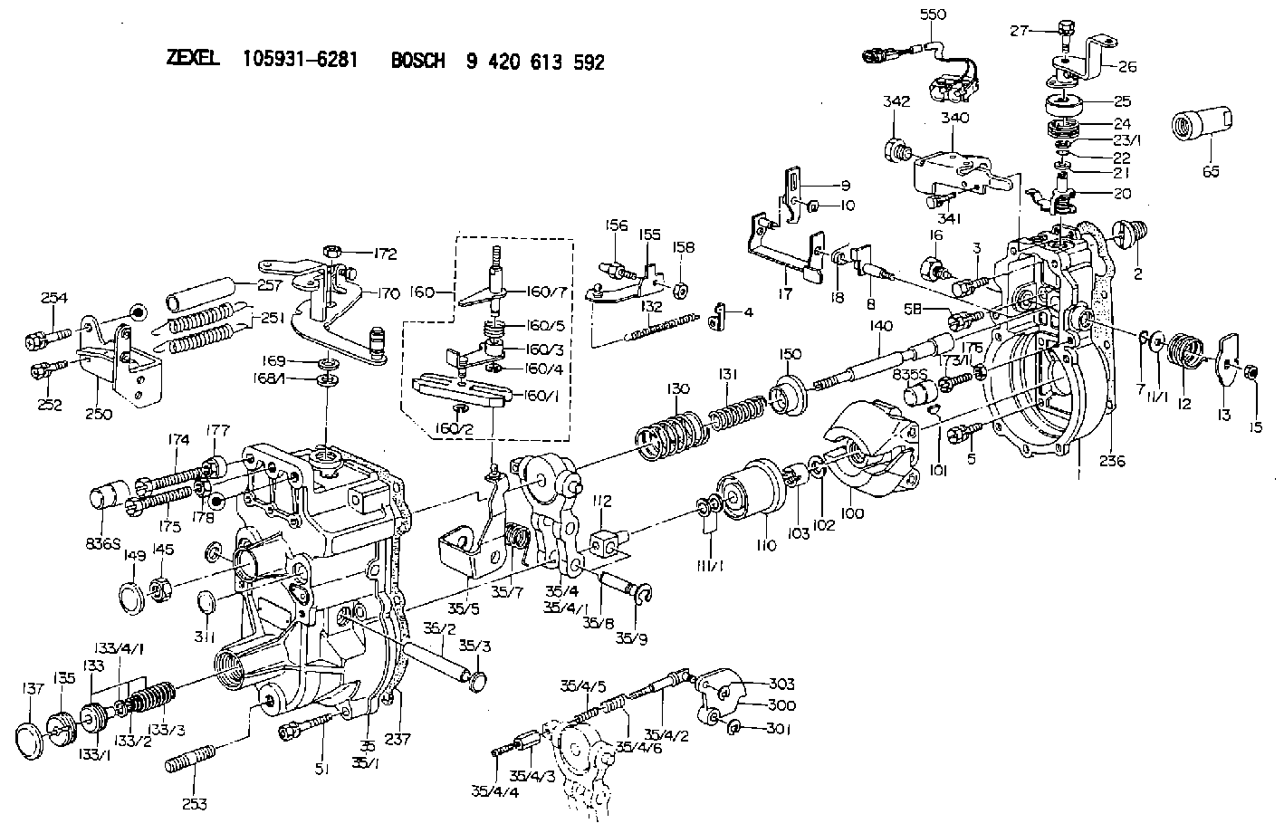
9 420 613 592
9420613592
ZEXEL
105931-6281
1059316281
Rating:
Scheme ###:
| 1. | [1] | 159200-4920 | GOVERNOR HOUSING |
| 2. | [1] | 154007-0200 | ADAPTOR |
| 3. | [1] | 020018-1840 | BLEEDER SCREW M8P1.25L18 |
| 4. | [1] | 159232-0201 | PLATE |
| 5. | [5] | 029010-6810 | BLEEDER SCREW |
| 5B. | [1] | 020106-1640 | BLEEDER SCREW M6P1.0L14 |
| 7. | [1] | 016530-1010 | O-RING |
| 8. | [1] | 159205-2321 | LEVER SHAFT |
| 9. | [1] | 159202-1802 | CONTROL LEVER |
| 10. | [1] | 016010-0810 | LOCKING WASHER |
| 11/1. | [0] | 029311-0220 | SHIM D18&10.3T0.2 |
| 11/1. | [0] | 029311-0230 | SHIM D18&10.3T0.5 |
| 11/1. | [0] | 029311-0430 | SHIM D18&10.3T0.30 |
| 11/1. | [0] | 029311-0440 | SHIM D18&10.3T0.40 |
| 11/1. | [0] | 029311-0450 | SHIM D18&10.3T0.25 |
| 11/1. | [0] | 029311-0460 | SHIM D18&10.3T0.35 |
| 11/1. | [0] | 139410-3300 | SHIM D18&10.3T0.6 |
| 11/1. | [0] | 139410-3400 | SHIM D18&10.3T0.8 |
| 11/1. | [0] | 139410-3500 | SHIM D18&10.3T0.9 |
| 12. | [1] | 159215-0000 | COILED SPRING |
| 13. | [1] | 159242-6601 | CONTROL LEVER |
| 15. | [1] | 013020-8040 | UNION NUT M8P1.25H7 |
| 16. | [1] | 159237-5200 | CAPSULE |
| 17. | [1] | 159202-1920 | CONTROL LEVER |
| 18. | [1] | 159215-0300 | COILED SPRING |
| 20. | [1] | 159242-0220 | CONTROL LEVER |
| 21. | [1] | 159242-0600 | BUSHING |
| 22. | [1] | 016530-1010 | O-RING |
| 23/1. | [0] | 029311-0220 | SHIM D18&10.3T0.2 |
| 23/1. | [0] | 029311-0230 | SHIM D18&10.3T0.5 |
| 23/1. | [0] | 029311-0430 | SHIM D18&10.3T0.30 |
| 23/1. | [0] | 029311-0440 | SHIM D18&10.3T0.40 |
| 23/1. | [0] | 029311-0450 | SHIM D18&10.3T0.25 |
| 23/1. | [0] | 029311-0460 | SHIM D18&10.3T0.35 |
| 23/1. | [0] | 139410-3300 | SHIM D18&10.3T0.6 |
| 23/1. | [0] | 139410-3400 | SHIM D18&10.3T0.8 |
| 23/1. | [0] | 139410-3500 | SHIM D18&10.3T0.9 |
| 24. | [1] | 159215-2000 | COILED SPRING |
| 25. | [1] | 159235-5800 | CAP |
| 26. | [1] | 159249-7120 | CONTROL LEVER |
| 27. | [1] | 020006-4040 | BLEEDER SCREW |
| 35. | [1] | 159251-3920 | GOVERNOR COVER |
| 35/1. | [1] | 159201-3422 | GOVERNOR COVER |
| 35/2. | [1] | 159205-0400 | LEVER SHAFT |
| 35/3. | [2] | 159237-0200 | CAPSULE |
| 35/4. | [1] | 159253-0720 | TENSIONING LEVER |
| 35/4/1. | [1] | 159203-0720 | TENSIONING LEVER |
| 35/4/2. | [1] | 159204-5021 | RACK |
| 35/4/3. | [1] | 159233-0300 | UNION NUT |
| 35/4/4. | [1] | 159234-0300 | FLAT-HEAD SCREW |
| 35/4/5. | [1] | 159216-0000 | COILED SPRING |
| 35/4/6. | [1] | 159216-0100 | COILED SPRING |
| 35/5. | [1] | 159203-5720 | GUIDE LEVER |
| 35/7. | [1] | 159215-1701 | COILED SPRING |
| 35/8. | [1] | 159231-2000 | BEARING PIN |
| 35/9. | [2] | 016010-0610 | LOCKING WASHER |
| 51. | [7] | 020106-3840 | BLEEDER SCREW |
| 65. | [1] | 154050-1720 | STOPPING DEVICE |
| 100. | [1] | 154100-9520 | FLYWEIGHT ASSEMBLY |
| 101. | [1] | 025803-1610 | WOODRUFF KEY |
| 102. | [1] | 029321-2020 | LOCKING WASHER |
| 103. | [1] | 029231-2030 | UNION NUT |
| 110. | [1] | 154123-2320 | SLIDING PIECE |
| 111/1. | [0] | 029311-0010 | SHIM D14&10.1T0.2 |
| 111/1. | [0] | 029311-0180 | SHIM D14&10.1T0.3 |
| 111/1. | [0] | 029311-0190 | SHIM D14&10.1T0.40 |
| 111/1. | [0] | 029311-0210 | SHIM D14&10.1T1 |
| 111/1. | [0] | 139410-0000 | SHIM D14.0&10.1T0.5 |
| 111/1. | [0] | 139410-0100 | SHIM D14.0&10.1T1.5 |
| 111/1. | [0] | 139410-3000 | SHIM D14&10.1T2.0 |
| 111/1. | [0] | 139410-3100 | SHIM D14&10.1T3.0 |
| 111/1. | [0] | 139410-3200 | SHIM D14&10.1T4.0 |
| 112. | [1] | 159236-0200 | TERMINAL STUD |
| 130. | [1] | 159210-0700 | GOVERNOR SPRING |
| 131. | [1] | 159211-2600 | COILED SPRING |
| 132. | [1] | 159214-0000 | COILED SPRING |
| 133. | [1] | 159212-5920 | SPRING PACK |
| 133/1. | [1] | 159234-5602 | GUIDE SLEEVE |
| 133/2. | [1] | 159212-4700 | COILED SPRING |
| 133/3. | [1] | 159212-5700 | COILED SPRING |
| 133/4/1. | [0] | 029310-9240 | SHIM D11.9&9T0.1 |
| 133/4/1. | [0] | 029310-9250 | SHIM D11.9&9T0.2 |
| 133/4/1. | [0] | 029310-9260 | SHIM D11.9&9T0.25 |
| 133/4/1. | [0] | 029310-9270 | SHIM D11.9&9T1.0 |
| 133/4/1. | [0] | 139409-0100 | SHIM D11.9&9T0.3 |
| 133/4/1. | [0] | 139409-0200 | SHIM D11.9&9T0.5 |
| 133/4/1. | [0] | 139409-0300 | SHIM D11.5&9T0.8 |
| 135. | [1] | 159248-2700 | FLAT-HEAD SCREW |
| 137. | [1] | 159237-5300 | CAPSULE |
| 140. | [1] | 159205-2101 | LEVER SHAFT |
| 145. | [1] | 159233-5700 | UNION NUT |
| 149. | [1] | 159237-5400 | CAPSULE |
| 150. | [1] | 159235-5300 | SLOTTED WASHER |
| 155. | [1] | 159204-5120 | STRAP |
| 156. | [1] | 159233-5800 | BLEEDER SCREW |
| 158. | [1] | 013020-5240 | UNION NUT M5P0.8H4 |
| 160. | [1] | 159252-0821 | LEVER GROUP |
| 160/1. | [1] | 159202-2200 | CONTROL LEVER |
| 160/2. | [1] | 016010-0810 | LOCKING WASHER |
| 160/3. | [1] | 159202-2120 | CONTROL LEVER |
| 160/4. | [1] | 016010-0810 | LOCKING WASHER |
| 160/5. | [1] | 159215-2301 | COILED SPRING |
| 160/7. | [1] | 159205-2222 | LEVER SHAFT |
| 168/1. | [0] | 029311-0640 | SHIM D26.0&10.2T0.95 |
| 168/1. | [0] | 029311-0650 | SHIM D26.0&10.2T0.20 |
| 168/1. | [0] | 029311-0660 | SHIM D26.0&10.2T0.25 |
| 168/1. | [0] | 029311-0670 | SHIM D26.0&10.2T0.30 |
| 168/1. | [0] | 029311-0680 | SHIM D26.0&10.2T0.35 |
| 168/1. | [0] | 029311-0690 | SHIM D26.0&10.2T0.40 |
| 168/1. | [0] | 029311-0700 | SHIM D26.0&10.2T0.50 |
| 168/1. | [0] | 139410-1400 | SHIM D26&10.2T0.7 |
| 168/1. | [0] | 139410-1500 | SHIM D26&10.2T0.9 |
| 168/1. | [0] | 139410-1600 | SHIM D26&10.2T0.8 |
| 168/1. | [0] | 139410-2700 | SHIM D26&10.2T0.6 |
| 169. | [1] | 139410-2300 | SHIM |
| 170. | [1] | 159261-0420 | CONTROL LEVER |
| 172. | [1] | 013020-8040 | UNION NUT M8P1.25H7 |
| 173/1. | [1] | 139006-3500 | BLEEDER SCREW M6P1.0L33 |
| 173/1. | [1] | 139006-3700 | BLEEDER SCREW M6P1.0L34 |
| 173/1. | [1] | 139006-3800 | BLEEDER SCREW M6P1.0L35 |
| 173/1. | [1] | 139006-3900 | BLEEDER SCREW M6P1.0L36 |
| 173/1. | [1] | 139006-5300 | BLEEDER SCREW M6P1.0L31 |
| 173/1. | [1] | 139006-5400 | BLEEDER SCREW M6P1.0L32 |
| 173/1. | [1] | 155615-2500 | BLEEDER SCREW M6P1.0L37 |
| 174. | [1] | 154010-7200 | BLEEDER SCREW M8P1.25L62 |
| 175. | [1] | 154010-2200 | BLEEDER SCREW |
| 176. | [1] | 159225-8600 | UNION NUT |
| 177. | [1] | 154011-2300 | UNION NUT |
| 178. | [1] | 154011-2800 | UNION NUT |
| 236. | [1] | 154390-0000 | GASKET |
| 237. | [1] | 159238-3100 | GASKET |
| 250. | [1] | 159228-1520 | BRACKET |
| 251. | [2] | 159243-4300 | COILED SPRING |
| 252. | [2] | 020106-1240 | BLEEDER SCREW M6P1.0L12 |
| 253. | [1] | 139010-1000 | STUD |
| 254. | [1] | 020118-1840 | BLEEDER SCREW |
| 257. | [2] | 154156-1800 | TUBE |
| 300. | [1] | 159280-5400 | CAM PLATE |
| 301. | [1] | 016010-0840 | LOCKING WASHER |
| 303. | [1] | 016010-0540 | LOCKING WASHER |
| 311. | [1] | 159237-0200 | CAPSULE |
| 340. | [1] | 159228-1700 | BRACKET |
| 341. | [2] | 020104-1040 | BLEEDER SCREW |
| 342. | [1] | 159248-0200 | BLEEDER SCREW |
| 550. | [1] | 153169-5020 | MICROSWITCH |
Include in #1:
101606-6690
as GOVERNOR
Cross reference number
Zexel num
Bosch num
Firm num
Name
Information:
Your truck may not have the same or all of the gauges as shown in the illustrations. The illustrations shown are of typical gauges.Gauges provide a "look" inside the engine. Be sure they are in good working order. You can determine what is the "normal" operating range by observing your gauges over a period of time.Noticeable changes in gauge readings are indicative of potential gauge or engine problems. This also applies to gauge readings that have changed significantly but are still within specifications. The cause of any sudden or significant change in the readings should be determined and corrected. Contact your Caterpillar dealer for assistance as needed. Oil Pressure - Indicates engine oil pressure. The oil pressure should be between 30 and 45 psi (207 and 310 kPa) when the engine is running at rated engine speed, with SAE 15W-40 oil, at 230°F (110°C) operating temperature. A lower pressureis normal at low idling speed.The "Check Engine" light will come on and a fault logged in the 3176 ECM system if oil pressure drops below 5 psi (35 kPa) at low idle rpm.
If no oil pressure is indicated, stop the engine. Engine damage can result.
Water Temperature - Indicates engine coolant temperature. It should normally indicate between 189°F (87°C) and 208°F (98°C). Maximum allowable temperature is 216°F (102°C) with the cooling system pressurized. Somewhat higher temperatures may occur under certain conditions. Ammeter - Indicates the amount of charge or discharge in the battery charging circuit. Normal operation of the indicator should be slightly to the positive (right) side of "0" (zero).With the engine running, during normal operation, if the indicator is constantly to the negative (left) side of "0" (zero) or shows excessive charge, have the charging system checked for malfunction. Tachometer - Indicates engine rpm (speed). The engine can be operated at high idle without damage, but should not be allowed to overspeed. Overspeeding when downshifting, going downhill, etc., can result in serious damage to your engine.
Do not exceed 2300 rpm in any situation.
Fuel Level - Indicates fuel level in the fuel tank. Electrically operated, it registers only when the key switch is ON. Fuel Pressure - Indicates fuel pressure to the unit injectors. The indicator should register in the NORMAL (green) range.Normal fuel pressure at low idle is 60 psi (410 kPa).Normal fuel pressure at TEL (Top Engine Limit) is 80 psi (550 kPa).
Never operate the 3176 Engine with the fuel pressure below 65 psi (450 kPa) at rated speed. Engine damage could result.
The "Check Engine" light will come on and a fault logged in the 3176 ECM system if fuel pressure drops below 65 psi (450 kPa) at rated speed (rpm).A drop in fuel pressure usually indicates a dirty or plugged fuel filter. Service Hour Meter - Indicates the total number of clock hours the engine has operated.