Information governor
BOSCH
9 420 613 581
9420613581
ZEXEL
105931-5911
1059315911

Rating:
Scheme ###:
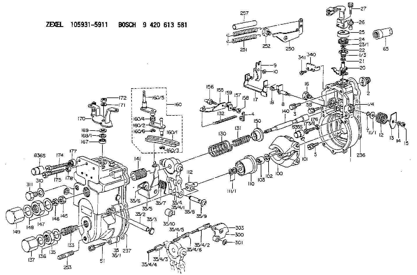
| 1. | [1] | 159200-2520 | GOVERNOR HOUSING |
| 1/3. | [1] | 154321-0400 | BUSHING |
| 1/4. | [1] | 154321-0400 | BUSHING |
| 2. | [1] | 154007-0200 | ADAPTOR |
| 3. | [1] | 020018-1840 | BLEEDER SCREW M8P1.25L18 |
| 4. | [1] | 159232-2820 | PLATE |
| 5. | [5] | 029010-6810 | BLEEDER SCREW |
| 5B. | [1] | 020106-1640 | BLEEDER SCREW M6P1.0L14 |
| 7. | [1] | 029631-0030 | O-RING &9.8W2.3 |
| 8. | [1] | 159205-2321 | LEVER SHAFT |
| 9. | [1] | 159202-2301 | CONTROL LEVER |
| 10. | [1] | 016010-0810 | LOCKING WASHER |
| 11/1. | [0] | 029311-0520 | SHIM D20.8&10.3T0.2 |
| 11/1. | [0] | 029311-0530 | SHIM D20.8&10.3T0.25 |
| 11/1. | [0] | 029311-0540 | SHIM D20.8&10.3T0.3 |
| 11/1. | [0] | 029311-0550 | SHIM D20.8&10.3T0.35 |
| 11/1. | [0] | 029311-0560 | SHIM D20.8&10.3T0.4 |
| 11/1. | [0] | 029311-0570 | SHIM D20.8&10.3T0.5 |
| 12. | [1] | 159215-0000 | COILED SPRING |
| 13. | [1] | 159242-0100 | CONTROL LEVER |
| 14. | [1] | 014110-8440 | LOCKING WASHER |
| 15. | [1] | 013020-8040 | UNION NUT M8P1.25H7 |
| 16. | [1] | 159237-0000 | CAPSULE |
| 17. | [1] | 159202-2420 | CONTROL LEVER |
| 18. | [1] | 159215-0300 | COILED SPRING |
| 20. | [1] | 159242-7820 | CONTROL LEVER |
| 21. | [1] | 159242-0600 | BUSHING |
| 22. | [1] | 016530-1010 | O-RING |
| 23/1. | [0] | 029311-0520 | SHIM D20.8&10.3T0.2 |
| 23/1. | [0] | 029311-0530 | SHIM D20.8&10.3T0.25 |
| 23/1. | [0] | 029311-0540 | SHIM D20.8&10.3T0.3 |
| 23/1. | [0] | 029311-0550 | SHIM D20.8&10.3T0.35 |
| 23/1. | [0] | 029311-0560 | SHIM D20.8&10.3T0.4 |
| 23/1. | [0] | 029311-0570 | SHIM D20.8&10.3T0.5 |
| 24. | [1] | 159215-2900 | COILED SPRING |
| 25. | [1] | 154322-0100 | CAP |
| 26. | [1] | 159249-7420 | CONTROL LEVER |
| 27. | [1] | 020006-1640 | BLEEDER SCREW M6P1L16 4T |
| 35. | [1] | 159255-3420 | GOVERNOR COVER |
| 35/1. | [1] | 159301-7520 | GOVERNOR COVER |
| 35/2. | [1] | 159205-0400 | LEVER SHAFT |
| 35/3. | [2] | 159237-0200 | CAPSULE |
| 35/4. | [1] | 159253-0220 | TENSIONING LEVER |
| 35/4/1. | [1] | 159203-0420 | TENSIONING LEVER |
| 35/4/2. | [1] | 159204-5021 | RACK |
| 35/4/3. | [1] | 159233-0300 | UNION NUT |
| 35/4/4. | [1] | 159234-0000 | FLAT-HEAD SCREW |
| 35/4/5. | [1] | 159216-0000 | COILED SPRING |
| 35/4/6. | [1] | 159216-0100 | COILED SPRING |
| 35/5. | [1] | 159203-5320 | GUIDE LEVER |
| 35/6. | [2] | 159235-5000 | BUSHING |
| 35/7. | [1] | 159215-0201 | COILED SPRING |
| 35/8. | [1] | 159231-1300 | BEARING PIN |
| 35/9. | [2] | 016010-0610 | LOCKING WASHER |
| 35/10. | [1] | 159238-1801 | BUSHING |
| 51. | [7] | 020106-3840 | BLEEDER SCREW |
| 65. | [1] | 154050-1720 | STOPPING DEVICE |
| 100. | [1] | 154101-0920 | FLYWEIGHT ASSEMBLY |
| 101. | [1] | 025803-1610 | WOODRUFF KEY |
| 102. | [1] | 029321-2020 | LOCKING WASHER |
| 103. | [1] | 029231-2030 | UNION NUT |
| 110. | [1] | 154123-2320 | SLIDING PIECE |
| 111/1. | [0] | 029311-0010 | SHIM D14&10.1T0.2 |
| 111/1. | [0] | 029311-0180 | SHIM D14&10.1T0.3 |
| 111/1. | [0] | 029311-0190 | SHIM D14&10.1T0.40 |
| 111/1. | [0] | 029311-0210 | SHIM D14&10.1T1 |
| 111/1. | [0] | 139410-0000 | SHIM D14.0&10.1T0.5 |
| 111/1. | [0] | 139410-0100 | SHIM D14.0&10.1T1.5 |
| 111/1. | [0] | 139410-3000 | SHIM D14&10.1T2.0 |
| 111/1. | [0] | 139410-3100 | SHIM D14&10.1T3.0 |
| 111/1. | [0] | 139410-3200 | SHIM D14&10.1T4.0 |
| 112. | [1] | 159236-0100 | TERMINAL STUD |
| 130. | [1] | 159210-4400 | GOVERNOR SPRING |
| 131. | [1] | 159211-2900 | GOVERNOR SPRING |
| 132. | [1] | 159214-0000 | COILED SPRING |
| 133. | [1] | 159212-4020 | HEADLESS SCREW |
| 135. | [1] | 139220-0200 | UNION NUT |
| 136. | [2] | 026520-2440 | GASKET D23.9&20.2T1 |
| 137. | [1] | 159248-0700 | CAP |
| 140. | [1] | 159205-1801 | LEVER SHAFT |
| 141. | [1] | 159234-5200 | GUIDE SLEEVE |
| 145. | [1] | 159233-5000 | UNION NUT |
| 146. | [1] | 023020-8040 | UNION NUT M8P1H5 |
| 147. | [1] | 139222-0200 | UNION NUT |
| 148. | [2] | 026522-2740 | GASKET D26.9&22.2T1 |
| 149. | [1] | 159237-5000 | CAP |
| 150. | [1] | 159235-5300 | SLOTTED WASHER |
| 155. | [1] | 159204-7920 | STRAP |
| 156. | [1] | 159237-0300 | BLEEDER SCREW |
| 157. | [1] | 014110-5440 | LOCKING WASHER |
| 158. | [1] | 159233-5620 | UNION NUT |
| 159. | [1] | 159242-0800 | PLATE |
| 160. | [1] | 159252-0521 | LEVER GROUP |
| 160/1. | [1] | 159202-1400 | CONTROL LEVER |
| 160/2. | [1] | 159202-1520 | CONTROL LEVER |
| 160/3. | [1] | 016010-0610 | LOCKING WASHER |
| 160/4. | [1] | 159215-1300 | COILED SPRING |
| 160/5. | [1] | 159205-1721 | LEVER SHAFT |
| 160/6. | [1] | 016010-0810 | LOCKING WASHER |
| 167. | [1] | 029621-0080 | PACKING RING |
| 168/1. | [0] | 029311-0640 | SHIM D26.0&10.2T0.95 |
| 168/1. | [0] | 029311-0650 | SHIM D26.0&10.2T0.20 |
| 168/1. | [0] | 029311-0660 | SHIM D26.0&10.2T0.25 |
| 168/1. | [0] | 029311-0670 | SHIM D26.0&10.2T0.30 |
| 168/1. | [0] | 029311-0680 | SHIM D26.0&10.2T0.35 |
| 168/1. | [0] | 029311-0690 | SHIM D26.0&10.2T0.40 |
| 168/1. | [0] | 029311-0700 | SHIM D26.0&10.2T0.50 |
| 168/1. | [0] | 139410-1400 | SHIM D26&10.2T0.7 |
| 168/1. | [0] | 139410-1500 | SHIM D26&10.2T0.9 |
| 168/1. | [0] | 139410-1600 | SHIM D26&10.2T0.8 |
| 168/1. | [0] | 139410-2700 | SHIM D26&10.2T0.6 |
| 169. | [1] | 139410-2300 | SHIM |
| 170. | [1] | 159261-8020 | CONTROL LEVER |
| 171. | [1] | 014110-8440 | LOCKING WASHER |
| 172. | [1] | 013020-8040 | UNION NUT M8P1.25H7 |
| 173/1. | [1] | 139006-3500 | BLEEDER SCREW M6P1.0L33 |
| 173/1. | [1] | 139006-3700 | BLEEDER SCREW M6P1.0L34 |
| 173/1. | [1] | 139006-3800 | BLEEDER SCREW M6P1.0L35 |
| 173/1. | [1] | 139006-3900 | BLEEDER SCREW M6P1.0L36 |
| 173/1. | [1] | 139006-5300 | BLEEDER SCREW M6P1.0L31 |
| 173/1. | [1] | 139006-5400 | BLEEDER SCREW M6P1.0L32 |
| 173/1. | [1] | 155615-2500 | BLEEDER SCREW M6P1.0L37 |
| 174. | [1] | 154010-8000 | BLEEDER SCREW |
| 175. | [1] | 154010-8100 | BLEEDER SCREW M8P1.25L65 |
| 176. | [1] | 159225-8600 | UNION NUT |
| 177. | [1] | 154011-2300 | UNION NUT |
| 178. | [1] | 154011-0100 | HEXAGON NUT |
| 236. | [1] | 154390-0000 | GASKET |
| 237. | [1] | 154390-1100 | GASKET |
| 250. | [1] | 159225-5420 | BRACKET |
| 251. | [2] | 159243-4600 | COILED SPRING |
| 252. | [1] | 159248-0200 | BLEEDER SCREW |
| 253. | [1] | 139010-1000 | STUD |
| 257. | [2] | 154156-0500 | TUBE |
| 300. | [1] | 159280-3900 | CAM PLATE |
| 301. | [1] | 016010-0840 | LOCKING WASHER |
| 303. | [1] | 016010-0540 | LOCKING WASHER |
| 310. | [1] | 026516-2040 | GASKET D19.9&16.2T1 |
| 311. | [1] | 159237-0100 | CAPSULE |
| 340. | [1] | 159228-2300 | PLATE |
| 341. | [2] | 020104-1040 | BLEEDER SCREW |
| 835S. | [1] | 154062-1900 | CAP D12L24 |
| 836S. | [1] | 154062-1700 | CAP D20L32 |
Include in #1:
101606-6260
as GOVERNOR
Cross reference number
Zexel num
Bosch num
Firm num
Name
Information:
Cooling
Never add coolant to an overheated engine; allow the engine to cool first.Check specific gravity of antifreeze solution frequently in cold weather to assure adequate protection.Coolant should be drained and replaced "Every 2000 Service Meter Units." With additions of Caterpillar Cooling System Inhibitor or the use of Coolant Conditioner Elements as recommended, the drain period can be extended to "Every 4000 Service Meter Units."All water is corrosive at engine operating temperature. The cooling system should be protected with inhibitor at all times regardless of concentration of antifreeze. This can be done by maintaining a 3% concentration of liquid Caterpillar Cooling System Inhibitor or by using Coolant Conditioner Elements.Never use both the liquid cooling system inhibitor and coolant elements at the same time.Do not use Caterpillar Cooling System Inhibitor or Coolant Conditioner Elements with Dowtherm 209 Full-Fill Coolant.
Whenever draining and refilling cooling system, always recheck the coolant level when the engine reaches normal operating temperature.Filling at over 5 U.S. gallons (19 liters) per minute can cause air pockets in the cooling system.Premix antifreeze solution to provide protection to the lowest expected ambient temperature. Pure undiluted antifreeze will freeze at -10°F (-23°C).Operate with a thermostat in the cooling system all year-round. Cooling system problems can arise without a thermostat.Electrical
When using jumper cables to start the engine, be sure to connect in parallel: POSITIVE (+) to POSITIVE (+) and NEGATIVE (-) to NEGATIVE (-).
Scheduled Oil Sampling
Use Scheduled Oil Sampling to monitor the engine's condition and maintenance requirements.Each oil sample should be taken when the oil is hot, and well mixed, to insure a sample which is representative of the oil in the compartment.Consult your Caterpillar dealer for complete information, and assistance in establishing a Scheduled Oil Sampling program for your equipment.Fuel
Fill fuel tank at the end of each day of operation to drive out moisture laden air and to prevent condensation. Do not fill the tank to the brim. The fuel expands when it gets warm and may overflow.
Water and sediment should be drained from the fuel tank at the start of each shift or after the fuel tank has been filled and allowed to stand for 5 to 10 minutes.Drain fuel tank of moisture and sediment as required by prevailing conditions.After changing fuel filters, always bleed fuel system to remove air bubbles from system.Air Intake
Service air cleaners when RED band in indicator locks in visible position.