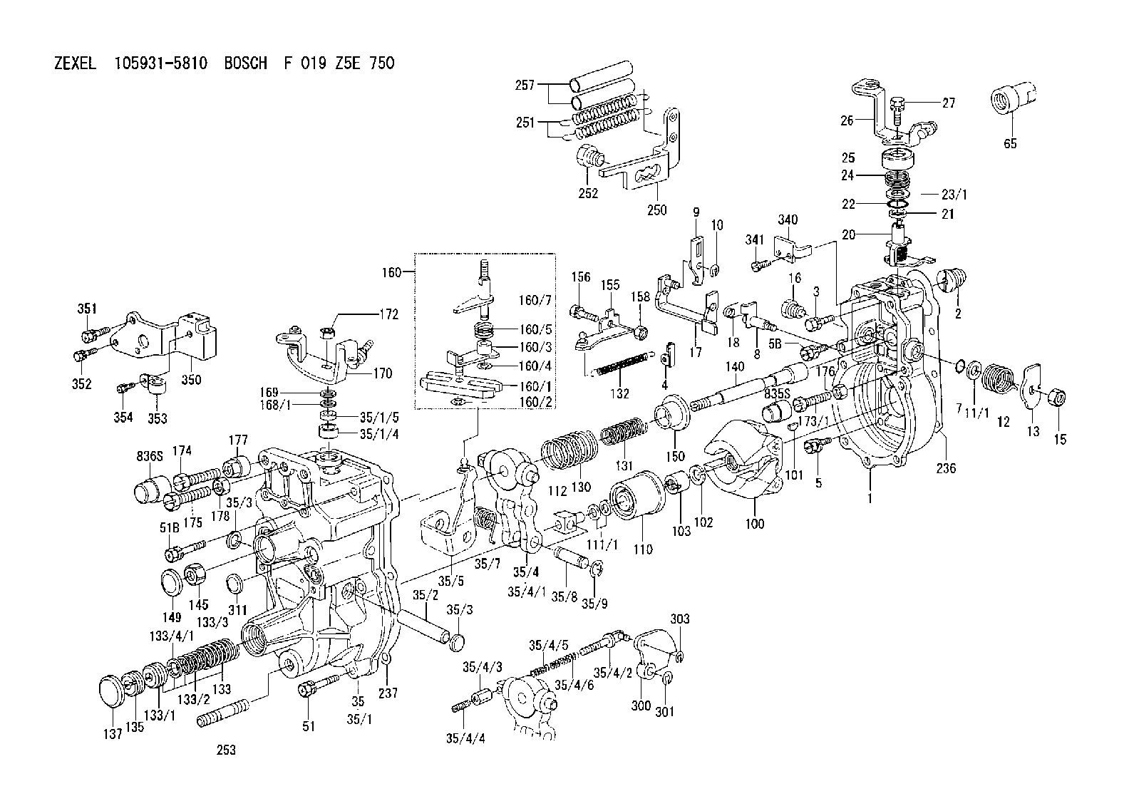
Information governor
BOSCH
F 019 Z5E 750
f019z5e750
ZEXEL
105931-5810
1059315810
MITSUBISHI
ME726271
me726271

Rating:
Scheme ###:
| 1. | [1] | 159200-4920 | GOVERNOR HOUSING |
| 2. | [1] | 154007-0200 | ADAPTOR |
| 3. | [1] | 020018-1840 | BLEEDER SCREW M8P1.25L18 |
| 4. | [1] | 159232-2620 | PLATE |
| 5. | [5] | 029010-6810 | BLEEDER SCREW |
| 5B. | [1] | 020106-1640 | BLEEDER SCREW M6P1.0L14 |
| 7. | [1] | 016530-1010 | O-RING |
| 8. | [1] | 159205-2321 | LEVER SHAFT |
| 9. | [1] | 159202-1802 | CONTROL LEVER |
| 10. | [1] | 016010-0810 | LOCKING WASHER |
| 11/1. | [0] | 029311-0220 | SHIM D18&10.3T0.2 |
| 11/1. | [0] | 029311-0230 | SHIM D18&10.3T0.5 |
| 11/1. | [0] | 029311-0430 | SHIM D18&10.3T0.30 |
| 11/1. | [0] | 029311-0440 | SHIM D18&10.3T0.40 |
| 11/1. | [0] | 029311-0450 | SHIM D18&10.3T0.25 |
| 11/1. | [0] | 029311-0460 | SHIM D18&10.3T0.35 |
| 11/1. | [0] | 139410-3300 | SHIM D18&10.3T0.6 |
| 11/1. | [0] | 139410-3400 | SHIM D18&10.3T0.8 |
| 11/1. | [0] | 139410-3500 | SHIM D18&10.3T0.9 |
| 12. | [1] | 159215-0000 | COILED SPRING |
| 13. | [1] | 159242-6601 | CONTROL LEVER |
| 15. | [1] | 013020-8040 | UNION NUT M8P1.25H7 |
| 16. | [1] | 159237-5200 | CAPSULE |
| 17. | [1] | 159202-1920 | CONTROL LEVER |
| 18. | [1] | 159215-0300 | COILED SPRING |
| 20. | [1] | 159242-0220 | CONTROL LEVER |
| 21. | [1] | 159242-0600 | BUSHING |
| 22. | [1] | 016530-1010 | O-RING |
| 23/1. | [0] | 029311-0220 | SHIM D18&10.3T0.2 |
| 23/1. | [0] | 029311-0230 | SHIM D18&10.3T0.5 |
| 23/1. | [0] | 029311-0430 | SHIM D18&10.3T0.30 |
| 23/1. | [0] | 029311-0440 | SHIM D18&10.3T0.40 |
| 23/1. | [0] | 029311-0450 | SHIM D18&10.3T0.25 |
| 23/1. | [0] | 029311-0460 | SHIM D18&10.3T0.35 |
| 23/1. | [0] | 139410-3300 | SHIM D18&10.3T0.6 |
| 23/1. | [0] | 139410-3400 | SHIM D18&10.3T0.8 |
| 23/1. | [0] | 139410-3500 | SHIM D18&10.3T0.9 |
| 24. | [1] | 159215-2000 | COILED SPRING |
| 25. | [1] | 159235-5800 | CAP |
| 26. | [1] | 159249-8520 | CONTROL LEVER |
| 27. | [1] | 020006-1640 | BLEEDER SCREW M6P1L16 4T |
| 35. | [1] | 159251-3920 | GOVERNOR COVER |
| 35/1. | [1] | 159201-3422 | GOVERNOR COVER |
| 35/1/4. | [1] | 159230-0902 | BUSHING |
| 35/1/5. | [1] | 029621-0080 | PACKING RING |
| 35/2. | [1] | 159205-0400 | LEVER SHAFT |
| 35/3. | [2] | 159237-0200 | CAPSULE |
| 35/3. | [2] | 159237-0200 | CAPSULE |
| 35/4. | [1] | 159253-0720 | TENSIONING LEVER |
| 35/4/1. | [1] | 159203-0720 | TENSIONING LEVER |
| 35/4/2. | [1] | 159204-5021 | RACK |
| 35/4/3. | [1] | 159233-0300 | UNION NUT |
| 35/4/4. | [1] | 159234-0300 | FLAT-HEAD SCREW |
| 35/4/5. | [1] | 159216-0000 | COILED SPRING |
| 35/4/6. | [1] | 159216-0100 | COILED SPRING |
| 35/5. | [1] | 159203-5720 | GUIDE LEVER |
| 35/7. | [1] | 159215-1701 | COILED SPRING |
| 35/8. | [1] | 159231-2000 | BEARING PIN |
| 35/9. | [2] | 016010-0610 | LOCKING WASHER |
| 51. | [6] | 020106-3840 | BLEEDER SCREW |
| 51B. | [1] | 020106-4040 | BLEEDER SCREW |
| 65. | [1] | 154050-1720 | STOPPING DEVICE |
| 100. | [1] | 154100-9520 | FLYWEIGHT ASSEMBLY |
| 101. | [1] | 025803-1610 | WOODRUFF KEY |
| 102. | [1] | 029321-2020 | LOCKING WASHER |
| 103. | [1] | 029231-2030 | UNION NUT |
| 110. | [1] | 154123-2320 | SLIDING PIECE |
| 111/1. | [0] | 029311-0010 | SHIM D14&10.1T0.2 |
| 111/1. | [0] | 029311-0180 | SHIM D14&10.1T0.3 |
| 111/1. | [0] | 029311-0190 | SHIM D14&10.1T0.40 |
| 111/1. | [0] | 029311-0210 | SHIM D14&10.1T1 |
| 111/1. | [0] | 139410-0000 | SHIM D14.0&10.1T0.5 |
| 111/1. | [0] | 139410-0100 | SHIM D14.0&10.1T1.5 |
| 111/1. | [0] | 139410-3000 | SHIM D14&10.1T2.0 |
| 111/1. | [0] | 139410-3100 | SHIM D14&10.1T3.0 |
| 111/1. | [0] | 139410-3200 | SHIM D14&10.1T4.0 |
| 112. | [1] | 159236-0200 | TERMINAL STUD |
| 130. | [1] | 159210-2700 | COILED SPRING |
| 131. | [1] | 159211-3000 | GOVERNOR SPRING |
| 132. | [1] | 159214-0000 | COILED SPRING |
| 133. | [1] | 159212-4720 | SPRING PACK |
| 133/1. | [1] | 159234-5602 | GUIDE SLEEVE |
| 133/2. | [1] | 159212-4700 | COILED SPRING |
| 133/3. | [1] | 159212-4600 | COILED SPRING |
| 133/4/1. | [0] | 029310-9240 | SHIM D11.9&9T0.1 |
| 133/4/1. | [0] | 029310-9250 | SHIM D11.9&9T0.2 |
| 133/4/1. | [0] | 029310-9260 | SHIM D11.9&9T0.25 |
| 133/4/1. | [0] | 029310-9270 | SHIM D11.9&9T1.0 |
| 133/4/1. | [0] | 139409-0100 | SHIM D11.9&9T0.3 |
| 133/4/1. | [0] | 139409-0200 | SHIM D11.9&9T0.5 |
| 133/4/1. | [0] | 139409-0300 | SHIM D11.5&9T0.8 |
| 135. | [1] | 159248-2700 | FLAT-HEAD SCREW |
| 137. | [1] | 159237-5300 | CAPSULE |
| 140. | [1] | 159205-2101 | LEVER SHAFT |
| 145. | [1] | 159233-5700 | UNION NUT |
| 149. | [1] | 159237-5400 | CAPSULE |
| 150. | [1] | 159235-5300 | SLOTTED WASHER |
| 155. | [1] | 159204-7720 | STRAP |
| 156. | [1] | 159233-5800 | BLEEDER SCREW |
| 158. | [1] | 013020-5240 | UNION NUT M5P0.8H4 |
| 160. | [1] | 159252-0821 | LEVER GROUP |
| 160/1. | [1] | 159202-2200 | CONTROL LEVER |
| 160/2. | [1] | 016010-0810 | LOCKING WASHER |
| 160/3. | [1] | 159202-2120 | CONTROL LEVER |
| 160/4. | [1] | 016010-0810 | LOCKING WASHER |
| 160/5. | [1] | 159215-2301 | COILED SPRING |
| 160/7. | [1] | 159205-2222 | LEVER SHAFT |
| 168/1. | [0] | 029311-0640 | SHIM D26.0&10.2T0.95 |
| 168/1. | [0] | 029311-0650 | SHIM D26.0&10.2T0.20 |
| 168/1. | [0] | 029311-0660 | SHIM D26.0&10.2T0.25 |
| 168/1. | [0] | 029311-0670 | SHIM D26.0&10.2T0.30 |
| 168/1. | [0] | 029311-0680 | SHIM D26.0&10.2T0.35 |
| 168/1. | [0] | 029311-0690 | SHIM D26.0&10.2T0.40 |
| 168/1. | [0] | 029311-0700 | SHIM D26.0&10.2T0.50 |
| 168/1. | [0] | 139410-1400 | SHIM D26&10.2T0.7 |
| 168/1. | [0] | 139410-1500 | SHIM D26&10.2T0.9 |
| 168/1. | [0] | 139410-1600 | SHIM D26&10.2T0.8 |
| 168/1. | [0] | 139410-2700 | SHIM D26&10.2T0.6 |
| 169. | [1] | 139410-2300 | SHIM |
| 170. | [1] | 159261-5820 | CONTROL LEVER |
| 172. | [1] | 013020-8040 | UNION NUT M8P1.25H7 |
| 173/1. | [1] | 139006-3500 | BLEEDER SCREW M6P1.0L33 |
| 173/1. | [1] | 139006-3700 | BLEEDER SCREW M6P1.0L34 |
| 173/1. | [1] | 139006-3800 | BLEEDER SCREW M6P1.0L35 |
| 173/1. | [1] | 139006-3900 | BLEEDER SCREW M6P1.0L36 |
| 173/1. | [1] | 139006-5300 | BLEEDER SCREW M6P1.0L31 |
| 173/1. | [1] | 139006-5400 | BLEEDER SCREW M6P1.0L32 |
| 173/1. | [1] | 155615-2500 | BLEEDER SCREW M6P1.0L37 |
| 174. | [1] | 154010-7200 | BLEEDER SCREW M8P1.25L62 |
| 175. | [1] | 154010-2900 | BLEEDER SCREW |
| 176. | [1] | 159225-8600 | UNION NUT |
| 177. | [1] | 154011-2300 | UNION NUT |
| 178. | [1] | 154011-0100 | HEXAGON NUT |
| 236. | [1] | 154390-0000 | GASKET |
| 237. | [1] | 159238-3100 | GASKET |
| 250. | [1] | 159227-8020 | BRACKET |
| 251. | [2] | 159243-3800 | COILED SPRING |
| 252. | [1] | 159248-0200 | BLEEDER SCREW |
| 253. | [1] | 139010-0000 | STUD |
| 257. | [2] | 154156-0700 | TUBE |
| 300. | [1] | 159209-8500 | CAM PLATE |
| 301. | [1] | 016010-0840 | LOCKING WASHER |
| 303. | [1] | 016010-0540 | LOCKING WASHER |
| 311. | [1] | 159237-0200 | CAPSULE |
| 340. | [1] | 159245-8300 | PLATE |
| 341. | [2] | 020104-1040 | BLEEDER SCREW |
| 350. | [1] | 159227-7800 | BRACKET |
| 351. | [1] | 020118-1440 | BLEEDER SCREW |
| 352. | [2] | 020106-1240 | BLEEDER SCREW M6P1.0L12 |
| 353. | [1] | 159225-5120 | PLATE |
| 354. | [1] | 020106-0840 | BLEEDER SCREW |
| 835S. | [1] | 154062-1900 | CAP D12L24 |
| 836S. | [1] | 154062-1700 | CAP D20L32 |
Include in #1:
101606-6181
as GOVERNOR
Cross reference number
Zexel num
Bosch num
Firm num
Name
Information:
Start By:a. remove timing gear coverb. remove fuel injection pump housing and rack actuator package 1. Remove four bolts (2), plate (3) and idler gear (1). 2. If the camshaft is not going to be removed, use tooling (A) to remove camshaft gear (4).
Do not turn the crankshaft with the camshaft gear removed. Damage can be caused to the pistons and valves, or both.
3. Remove bolts (5) that hold timing gear plate (6) to the cylinder block.4. Remove timing gear plate (6). 5. Use tooling (B) to remove the bearing from the idler gear. The following steps are for the installation of the timing gears and plate.6. Install a new gasket on the timing gear plate.7. Put timing gear plate (6) in position on the cylinder block, and install the bolts that hold the timing gear plate to the cylinder block.8. Heat camshaft gear (4) to a maximum temperature of 315° C (600° F), and install it on the camshaft.9. Use tooling (B), and install the bearing in the idler gear. Set the gear on the front face, (face with timing marks). Drive the bearing from the rear face toward the front face of the gear. Install the bearing to a depth of 1.5 0.5 mm (.06 .02 in.) below the rear face of the idler gear.10. Install the idler gear, plate and bolts. Be sure No. 1 cylinder is at top center on the compression stroke. Install the idler gear so "V" mark (7) on the idler gear is in alignment with the "V" mark on the crankshaft gear. "K" marks (8) of the camshaft gear can be seen at the outer edges of the idler gear.End By:a. install fuel injection pump housing and rack actuator packageb. install timing gear cover