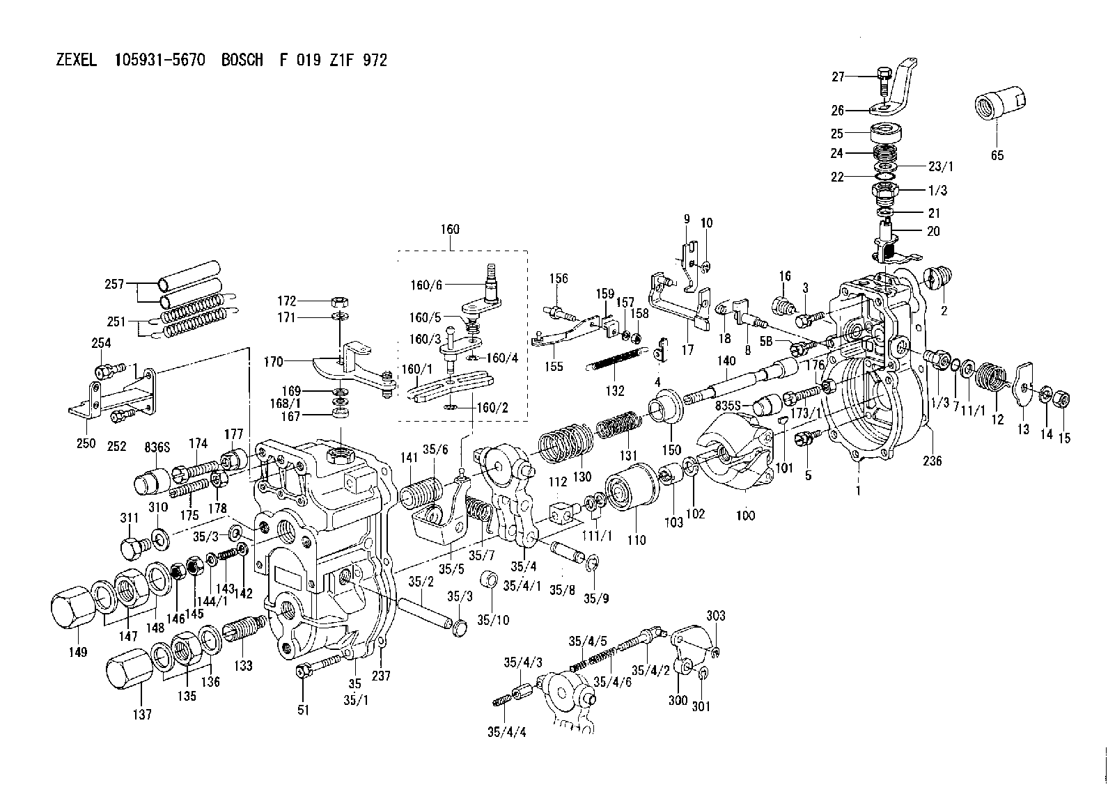
Information governor
BOSCH
F 019 Z1F 972
f019z1f972
ZEXEL
105931-5670
1059315670
ISUZU
1157701810
1157701810

Rating:
Scheme ###:
| 1. | [1] | 159200-1020 | GOVERNOR HOUSING |
| 1/3. | [2] | 154321-0400 | BUSHING |
| 1/3. | [2] | 154321-0400 | BUSHING |
| 2. | [1] | 154007-0200 | ADAPTOR |
| 3. | [1] | 020018-1840 | BLEEDER SCREW M8P1.25L18 |
| 4. | [1] | 159232-0201 | PLATE |
| 5. | [5] | 029010-6810 | BLEEDER SCREW |
| 5B. | [1] | 020106-1640 | BLEEDER SCREW M6P1.0L14 |
| 7. | [1] | 139710-0200 | O-RING |
| 8. | [1] | 159205-2321 | LEVER SHAFT |
| 9. | [1] | 159202-1201 | CONTROL LEVER |
| 10. | [1] | 016010-0810 | LOCKING WASHER |
| 11/1. | [0] | 029311-0520 | SHIM D20.8&10.3T0.2 |
| 11/1. | [0] | 029311-0530 | SHIM D20.8&10.3T0.25 |
| 11/1. | [0] | 029311-0540 | SHIM D20.8&10.3T0.3 |
| 11/1. | [0] | 029311-0550 | SHIM D20.8&10.3T0.35 |
| 11/1. | [0] | 029311-0560 | SHIM D20.8&10.3T0.4 |
| 11/1. | [0] | 029311-0570 | SHIM D20.8&10.3T0.5 |
| 12. | [1] | 159215-0000 | COILED SPRING |
| 13. | [1] | 159242-0100 | CONTROL LEVER |
| 14. | [1] | 014110-8440 | LOCKING WASHER |
| 15. | [1] | 013020-8040 | UNION NUT M8P1.25H7 |
| 16. | [1] | 159237-0000 | CAPSULE |
| 17. | [1] | 159202-0320 | CONTROL LEVER |
| 18. | [1] | 159215-0300 | COILED SPRING |
| 20. | [1] | 159242-0220 | CONTROL LEVER |
| 21. | [1] | 159242-0600 | BUSHING |
| 22. | [1] | 139710-0300 | O-RING |
| 23/1. | [0] | 029311-0520 | SHIM D20.8&10.3T0.2 |
| 23/1. | [0] | 029311-0530 | SHIM D20.8&10.3T0.25 |
| 23/1. | [0] | 029311-0540 | SHIM D20.8&10.3T0.3 |
| 23/1. | [0] | 029311-0550 | SHIM D20.8&10.3T0.35 |
| 23/1. | [0] | 029311-0560 | SHIM D20.8&10.3T0.4 |
| 23/1. | [0] | 029311-0570 | SHIM D20.8&10.3T0.5 |
| 24. | [1] | 159215-0000 | COILED SPRING |
| 25. | [1] | 154322-0100 | CAP |
| 26. | [1] | 159242-4900 | CONTROL LEVER |
| 27. | [1] | 020006-1640 | BLEEDER SCREW M6P1L16 4T |
| 35. | [1] | 159251-2120 | GOVERNOR COVER |
| 35/1. | [1] | 159201-1420 | GOVERNOR COVER |
| 35/2. | [1] | 159205-0400 | LEVER SHAFT |
| 35/3. | [2] | 159237-0200 | CAPSULE |
| 35/3. | [2] | 159237-0200 | CAPSULE |
| 35/4. | [1] | 159253-0220 | TENSIONING LEVER |
| 35/4/1. | [1] | 159203-0420 | TENSIONING LEVER |
| 35/4/2. | [1] | 159204-5021 | RACK |
| 35/4/3. | [1] | 159233-0300 | UNION NUT |
| 35/4/4. | [1] | 159234-0000 | FLAT-HEAD SCREW |
| 35/4/5. | [1] | 159216-0000 | COILED SPRING |
| 35/4/6. | [1] | 159216-0100 | COILED SPRING |
| 35/5. | [1] | 159203-5320 | GUIDE LEVER |
| 35/6. | [2] | 159235-5000 | BUSHING |
| 35/7. | [1] | 159215-0201 | COILED SPRING |
| 35/8. | [1] | 159231-1300 | BEARING PIN |
| 35/9. | [2] | 016010-0610 | LOCKING WASHER |
| 35/10. | [1] | 159238-1801 | BUSHING |
| 51. | [7] | 020106-3840 | BLEEDER SCREW |
| 65. | [1] | 154050-1720 | STOPPING DEVICE |
| 100. | [1] | 154100-9520 | FLYWEIGHT ASSEMBLY |
| 101. | [1] | 025803-1610 | WOODRUFF KEY |
| 102. | [1] | 029321-2020 | LOCKING WASHER |
| 103. | [1] | 029231-2030 | UNION NUT |
| 110. | [1] | 154123-2320 | SLIDING PIECE |
| 111/1. | [0] | 029311-0010 | SHIM D14&10.1T0.2 |
| 111/1. | [0] | 029311-0180 | SHIM D14&10.1T0.3 |
| 111/1. | [0] | 029311-0190 | SHIM D14&10.1T0.40 |
| 111/1. | [0] | 029311-0210 | SHIM D14&10.1T1 |
| 111/1. | [0] | 139410-0000 | SHIM D14.0&10.1T0.5 |
| 111/1. | [0] | 139410-0100 | SHIM D14.0&10.1T1.5 |
| 111/1. | [0] | 139410-3000 | SHIM D14&10.1T2.0 |
| 111/1. | [0] | 139410-3100 | SHIM D14&10.1T3.0 |
| 111/1. | [0] | 139410-3200 | SHIM D14&10.1T4.0 |
| 112. | [1] | 159236-0100 | TERMINAL STUD |
| 130. | [1] | 159210-6100 | GOVERNOR SPRING |
| 131. | [1] | 159211-0600 | GOVERNOR SPRING |
| 132. | [1] | 159214-0000 | COILED SPRING |
| 133. | [1] | 159212-1720 | HEADLESS SCREW |
| 135. | [1] | 139220-0200 | UNION NUT |
| 136. | [2] | 139520-0000 | GASKET |
| 137. | [1] | 159248-0700 | CAP |
| 140. | [1] | 159205-1001 | LEVER SHAFT |
| 141. | [1] | 159234-5400 | GUIDE SLEEVE |
| 142. | [1] | 159235-0200 | SPRING SEAT |
| 143. | [1] | 159213-0100 | COILED SPRING |
| 144/1. | [1] | 159238-0200 | SHIM D16.5&8.6T0.10 |
| 144/1. | [1] | 159238-0300 | SHIM D16.5&8.6T0.15 |
| 144/1. | [1] | 159238-0400 | SHIM D16.5&8.6T0.20 |
| 144/1. | [1] | 159238-0500 | SHIM D16.5&8.6T0.25 |
| 144/1. | [1] | 159238-0600 | SHIM D16.5&8.6T0.30 |
| 144/1. | [1] | 159238-0700 | SHIM D16.5&8.6T0.35 |
| 144/1. | [1] | 159238-0800 | SHIM D16.5&8.6T0.40 |
| 144/1. | [1] | 159238-0900 | SHIM D16.5&8.6T0.45 |
| 144/1. | [1] | 159238-1000 | SHIM D16.5&8.6T0.50 |
| 145. | [1] | 159233-5900 | UNION NUT |
| 146. | [1] | 023020-8040 | UNION NUT M8P1H5 |
| 147. | [1] | 139222-0200 | UNION NUT |
| 148. | [2] | 139522-0000 | GASKET |
| 149. | [1] | 159237-5000 | CAP |
| 150. | [1] | 159235-5300 | SLOTTED WASHER |
| 155. | [1] | 159204-0120 | STRAP |
| 156. | [1] | 159237-0300 | BLEEDER SCREW |
| 157. | [1] | 014110-5440 | LOCKING WASHER |
| 158. | [1] | 159233-5620 | UNION NUT |
| 159. | [1] | 159242-0800 | PLATE |
| 160. | [1] | 159252-0122 | LEVER GROUP |
| 160/1. | [1] | 159202-2200 | CONTROL LEVER |
| 160/2. | [1] | 016010-0810 | LOCKING WASHER |
| 160/3. | [1] | 159202-0220 | CONTROL LEVER |
| 160/4. | [1] | 016010-0810 | LOCKING WASHER |
| 160/5. | [1] | 159215-0400 | COILED SPRING |
| 160/6. | [1] | 159205-0621 | LEVER SHAFT |
| 167. | [1] | 139610-0600 | PACKING RING |
| 168/1. | [0] | 029311-0640 | SHIM D26.0&10.2T0.95 |
| 168/1. | [0] | 029311-0650 | SHIM D26.0&10.2T0.20 |
| 168/1. | [0] | 029311-0660 | SHIM D26.0&10.2T0.25 |
| 168/1. | [0] | 029311-0670 | SHIM D26.0&10.2T0.30 |
| 168/1. | [0] | 029311-0680 | SHIM D26.0&10.2T0.35 |
| 168/1. | [0] | 029311-0690 | SHIM D26.0&10.2T0.40 |
| 168/1. | [0] | 029311-0700 | SHIM D26.0&10.2T0.50 |
| 168/1. | [0] | 139410-1400 | SHIM D26&10.2T0.7 |
| 168/1. | [0] | 139410-1500 | SHIM D26&10.2T0.9 |
| 168/1. | [0] | 139410-1600 | SHIM D26&10.2T0.8 |
| 168/1. | [0] | 139410-2700 | SHIM D26&10.2T0.6 |
| 169. | [1] | 139410-2300 | SHIM |
| 170. | [1] | 159260-5320 | CONTROL LEVER |
| 171. | [1] | 014110-8440 | LOCKING WASHER |
| 172. | [1] | 013020-8040 | UNION NUT M8P1.25H7 |
| 173/1. | [1] | 139006-3500 | BLEEDER SCREW M6P1.0L33 |
| 173/1. | [1] | 139006-3700 | BLEEDER SCREW M6P1.0L34 |
| 173/1. | [1] | 139006-3800 | BLEEDER SCREW M6P1.0L35 |
| 173/1. | [1] | 139006-3900 | BLEEDER SCREW M6P1.0L36 |
| 173/1. | [1] | 139006-5300 | BLEEDER SCREW M6P1.0L31 |
| 173/1. | [1] | 139006-5400 | BLEEDER SCREW M6P1.0L32 |
| 173/1. | [1] | 155615-2500 | BLEEDER SCREW M6P1.0L37 |
| 174. | [1] | 154010-7200 | BLEEDER SCREW M8P1.25L62 |
| 175. | [1] | 154010-0100 | FLAT-HEAD SCREW |
| 176. | [1] | 159225-8600 | UNION NUT |
| 177. | [1] | 154011-2300 | UNION NUT |
| 178. | [1] | 154011-0100 | HEXAGON NUT |
| 236. | [1] | 154390-0000 | GASKET |
| 237. | [1] | 159238-3100 | GASKET |
| 250. | [1] | 159227-5520 | BRACKET |
| 251. | [2] | 159243-1200 | COILED SPRING |
| 252. | [2] | 020106-1240 | BLEEDER SCREW M6P1.0L12 |
| 254. | [1] | 020018-1640 | BLEEDER SCREW M8P1.25L16 4T |
| 257. | [2] | 154156-0500 | TUBE |
| 300. | [1] | 159280-0700 | CAM PLATE |
| 301. | [1] | 016010-0840 | LOCKING WASHER |
| 303. | [1] | 016010-0540 | LOCKING WASHER |
| 310. | [2] | 139516-0100 | GASKET |
| 311. | [1] | 159237-0100 | CAPSULE |
| 835S. | [1] | 154062-1900 | CAP D12L24 |
| 836S. | [1] | 154062-1700 | CAP D20L32 |
Include in #1:
101603-4573
as GOVERNOR
Cross reference number
Zexel num
Bosch num
Firm num
Name
105931-5670
F 019 Z1F 972
1157701810 ISUZU
GOVERNOR
* K
* K
Information:
1. Remove nuts (1), cover (2), and the gasket. 2. Put No. 1 piston at the top center compression position (TDC) with the following procedure:a. Remove plug (3), two bolts and cover (2) from the flywheel housing. b. Install tool (B) in the flywheel housing. Use tool (B) to slowly rotate the engine in the direction of normal rotation, (counterclockwise as seen from the flywheel end of the engine), until timing bolt (4) can be installed in the flywheel housing and into the hole in the flywheel. c. Remove the valve cover from the valve cover base. Check to see if both rocker arms (5) for the No. 1 cylinder can be moved backward and forward. The No. 1 piston is at the top center compression position (TDC) when the timing bolt is installed in the flywheel and both rocker arms for the No. 1 cylinder can be moved backward and forward. If both rocker arms cannot be moved, the No. 1 piston is not at the top center compression position (TDC). Remove the timing bolt from the flywheel and rotate the engine in the direction of normal rotation, (counterclockwise as seen from the flywheel end of the engine one full turn 360°, and install the timing bolt again.3. Remove the timing bolt, and use tool (B) to rotate the engine in the opposite direction of normal rotation (clockwise as seen from the flywheel end of the engine) a minimum of 30°. The timing is correct if tool (A) and the timing bolt can be installed at the same time. The timing procedure in the Testing and Adjustment Manual must be done again if the timing bolt and tool (A) can not be installed at the same time.4. Remove the plug from the timing pin hole in the fuel injection pump housing, and install tool (A) in the timing pin hole. 5. Remove eight bolts (6) and automatic timing advance (7). 6. Remove gear (9) from fuel injection pump camshaft (8).The following steps are for the installation procedure.7. Install gear (9) on fuel injection pump camshaft (8). 8. Install two 3/8 in. - 16 NC × 6 in. (152.4 mm) long guide bolts (10). Space the guide bolts evenly.
There is a light spring located beneath the flyweight cover (12). Hold cover (12) while removing last nut (11). Slowly remove flyweight cover (12) to avoid dropping the spring.
9. Remove four nuts (11) and remove flyweight cover (12). 10. Put automatic timing advance (13) in position on the fuel injection pump camshaft, and install four bolts (14). Tighten bolts (14) just past finger tight. Remove guide bolts (15). 11. Install four nuts (16) standard torque. Install tool (C). 12. Tighten four knurled nuts (17) finger tight.
Do not use any tools to tighten the knurled nuts.
13. Install all mounting bolts (14) and tighten to a torque of 3 N m (27 lb.in.).14. Loosen knurled nuts (17). Remove four nuts (16) and remove tool (C).15. Install the spring and flyweight cover
Have questions with 105931-5670?
Group cross 105931-5670 ZEXEL
Mitsubishi
Isuzu
Mitsubishi
Isuzu
105931-5670
F 019 Z1F 972
1157701810
GOVERNOR