Information governor
BOSCH
F 019 Z1E 498
f019z1e498
ZEXEL
105931-5410
1059315410
MITSUBISHI
ME723826
me723826

Rating:
Scheme ###:
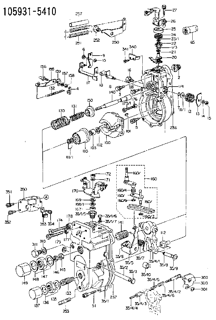
| 1. | [1] | 159200-2520 | GOVERNOR HOUSING |
| 1/3. | [1] | 154321-0400 | BUSHING |
| 1/4. | [1] | 154321-0400 | BUSHING |
| 2. | [1] | 154007-0200 | ADAPTOR |
| 3. | [1] | 020018-1840 | BLEEDER SCREW M8P1.25L18 |
| 4. | [1] | 159232-0801 | PLATE |
| 5. | [5] | 029010-6810 | BLEEDER SCREW |
| 5B. | [1] | 020106-1640 | BLEEDER SCREW M6P1.0L14 |
| 7. | [1] | 029631-0030 | O-RING &9.8W2.3 |
| 8. | [1] | 159205-2321 | LEVER SHAFT |
| 9. | [1] | 159202-2301 | CONTROL LEVER |
| 10. | [1] | 016010-0810 | LOCKING WASHER |
| 11/1. | [0] | 029311-0520 | SHIM D20.8&10.3T0.2 |
| 11/1. | [0] | 029311-0530 | SHIM D20.8&10.3T0.25 |
| 11/1. | [0] | 029311-0540 | SHIM D20.8&10.3T0.3 |
| 11/1. | [0] | 029311-0550 | SHIM D20.8&10.3T0.35 |
| 11/1. | [0] | 029311-0560 | SHIM D20.8&10.3T0.4 |
| 11/1. | [0] | 029311-0570 | SHIM D20.8&10.3T0.5 |
| 12. | [1] | 159215-0000 | COILED SPRING |
| 13. | [1] | 159242-0100 | CONTROL LEVER |
| 14. | [1] | 014110-8440 | LOCKING WASHER |
| 15. | [1] | 013020-8040 | UNION NUT M8P1.25H7 |
| 16. | [1] | 159237-0000 | CAPSULE |
| 17. | [1] | 159202-2420 | CONTROL LEVER |
| 18. | [1] | 159215-0300 | COILED SPRING |
| 20. | [1] | 159242-7820 | CONTROL LEVER |
| 21. | [1] | 159242-0600 | BUSHING |
| 22. | [1] | 016530-1010 | O-RING |
| 23/1. | [0] | 029311-0520 | SHIM D20.8&10.3T0.2 |
| 23/1. | [0] | 029311-0530 | SHIM D20.8&10.3T0.25 |
| 23/1. | [0] | 029311-0540 | SHIM D20.8&10.3T0.3 |
| 23/1. | [0] | 029311-0550 | SHIM D20.8&10.3T0.35 |
| 23/1. | [0] | 029311-0560 | SHIM D20.8&10.3T0.4 |
| 23/1. | [0] | 029311-0570 | SHIM D20.8&10.3T0.5 |
| 24. | [1] | 159215-2900 | COILED SPRING |
| 25. | [1] | 154322-0100 | CAP |
| 26. | [1] | 159249-7420 | CONTROL LEVER |
| 27. | [1] | 020006-1640 | BLEEDER SCREW M6P1L16 4T |
| 35. | [1] | 159251-4520 | GOVERNOR COVER |
| 35/1. | [1] | 159201-2410 | GOVERNOR COVER |
| 35/2. | [1] | 159205-0400 | LEVER SHAFT |
| 35/3. | [2] | 159237-0200 | CAPSULE |
| 35/4. | [1] | 159253-0220 | TENSIONING LEVER |
| 35/4/1. | [1] | 159203-0420 | TENSIONING LEVER |
| 35/4/2. | [1] | 159204-5021 | RACK |
| 35/4/3. | [1] | 159233-0300 | UNION NUT |
| 35/4/4. | [1] | 159234-0000 | FLAT-HEAD SCREW |
| 35/4/5. | [1] | 159216-0000 | COILED SPRING |
| 35/4/6. | [1] | 159216-0100 | COILED SPRING |
| 35/5. | [1] | 159203-5320 | GUIDE LEVER |
| 35/6. | [2] | 159235-5000 | BUSHING |
| 35/7. | [1] | 159215-0201 | COILED SPRING |
| 35/8. | [1] | 159231-1300 | BEARING PIN |
| 35/9. | [2] | 016010-0610 | LOCKING WASHER |
| 35/10. | [1] | 159238-1801 | BUSHING |
| 51. | [7] | 020106-3840 | BLEEDER SCREW |
| 65. | [1] | 154050-1720 | STOPPING DEVICE |
| 100. | [1] | 154101-0920 | FLYWEIGHT ASSEMBLY |
| 101. | [1] | 025803-1610 | WOODRUFF KEY |
| 102. | [1] | 029321-2020 | LOCKING WASHER |
| 103. | [1] | 029231-2030 | UNION NUT |
| 110. | [1] | 154123-2320 | SLIDING PIECE |
| 111/1. | [0] | 029311-0010 | SHIM D14&10.1T0.2 |
| 111/1. | [0] | 029311-0180 | SHIM D14&10.1T0.3 |
| 111/1. | [0] | 029311-0190 | SHIM D14&10.1T0.40 |
| 111/1. | [0] | 029311-0210 | SHIM D14&10.1T1 |
| 111/1. | [0] | 139410-0000 | SHIM D14.0&10.1T0.5 |
| 111/1. | [0] | 139410-0100 | SHIM D14.0&10.1T1.5 |
| 111/1. | [0] | 139410-3000 | SHIM D14&10.1T2.0 |
| 111/1. | [0] | 139410-3100 | SHIM D14&10.1T3.0 |
| 111/1. | [0] | 139410-3200 | SHIM D14&10.1T4.0 |
| 112. | [1] | 159236-0100 | TERMINAL STUD |
| 130. | [1] | 159210-4400 | GOVERNOR SPRING |
| 131. | [1] | 159211-2900 | GOVERNOR SPRING |
| 132. | [1] | 159214-0000 | COILED SPRING |
| 133. | [1] | 159212-4020 | HEADLESS SCREW |
| 135. | [1] | 139220-0200 | UNION NUT |
| 136. | [2] | 026520-2440 | GASKET D23.9&20.2T1 |
| 137. | [1] | 159248-0700 | CAP |
| 140. | [1] | 159205-1801 | LEVER SHAFT |
| 141. | [1] | 159234-5200 | GUIDE SLEEVE |
| 145. | [1] | 159233-5000 | UNION NUT |
| 146. | [1] | 023020-8040 | UNION NUT M8P1H5 |
| 147. | [1] | 139222-0200 | UNION NUT |
| 148. | [2] | 026522-2740 | GASKET D26.9&22.2T1 |
| 149. | [1] | 159237-5000 | CAP |
| 150. | [1] | 159235-5300 | SLOTTED WASHER |
| 155. | [1] | 159204-0320 | STRAP |
| 156. | [1] | 159237-0300 | BLEEDER SCREW |
| 157. | [1] | 014110-5440 | LOCKING WASHER |
| 158. | [1] | 159233-5620 | UNION NUT |
| 159. | [1] | 159242-0800 | PLATE |
| 160. | [1] | 159252-0521 | LEVER GROUP |
| 160/1. | [1] | 159202-1400 | CONTROL LEVER |
| 160/2. | [1] | 159202-1520 | CONTROL LEVER |
| 160/3. | [1] | 016010-0610 | LOCKING WASHER |
| 160/4. | [1] | 159215-1300 | COILED SPRING |
| 160/5. | [1] | 159205-1721 | LEVER SHAFT |
| 160/6. | [1] | 016010-0810 | LOCKING WASHER |
| 167. | [1] | 029621-0080 | PACKING RING |
| 168/1. | [0] | 029311-0640 | SHIM D26.0&10.2T0.95 |
| 168/1. | [0] | 029311-0650 | SHIM D26.0&10.2T0.20 |
| 168/1. | [0] | 029311-0660 | SHIM D26.0&10.2T0.25 |
| 168/1. | [0] | 029311-0670 | SHIM D26.0&10.2T0.30 |
| 168/1. | [0] | 029311-0680 | SHIM D26.0&10.2T0.35 |
| 168/1. | [0] | 029311-0690 | SHIM D26.0&10.2T0.40 |
| 168/1. | [0] | 029311-0700 | SHIM D26.0&10.2T0.50 |
| 168/1. | [0] | 139410-1400 | SHIM D26&10.2T0.7 |
| 168/1. | [0] | 139410-1500 | SHIM D26&10.2T0.9 |
| 168/1. | [0] | 139410-1600 | SHIM D26&10.2T0.8 |
| 168/1. | [0] | 139410-2700 | SHIM D26&10.2T0.6 |
| 169. | [1] | 139410-2300 | SHIM |
| 170. | [1] | 159261-1320 | CONTROL LEVER |
| 171. | [1] | 014110-8440 | LOCKING WASHER |
| 172. | [1] | 013020-8040 | UNION NUT M8P1.25H7 |
| 173/1. | [1] | 139006-3500 | BLEEDER SCREW M6P1.0L33 |
| 173/1. | [1] | 139006-3700 | BLEEDER SCREW M6P1.0L34 |
| 173/1. | [1] | 139006-3800 | BLEEDER SCREW M6P1.0L35 |
| 173/1. | [1] | 139006-3900 | BLEEDER SCREW M6P1.0L36 |
| 173/1. | [1] | 139006-5300 | BLEEDER SCREW M6P1.0L31 |
| 173/1. | [1] | 139006-5400 | BLEEDER SCREW M6P1.0L32 |
| 173/1. | [1] | 155615-2500 | BLEEDER SCREW M6P1.0L37 |
| 174. | [1] | 154010-8000 | BLEEDER SCREW |
| 175. | [1] | 154010-8100 | BLEEDER SCREW M8P1.25L65 |
| 176. | [1] | 159225-8600 | UNION NUT |
| 177. | [1] | 154011-2300 | UNION NUT |
| 178. | [1] | 154011-0100 | HEXAGON NUT |
| 236. | [1] | 154390-0000 | GASKET |
| 237. | [1] | 154390-1100 | GASKET |
| 250. | [1] | 159225-5420 | BRACKET |
| 251. | [2] | 159243-4600 | COILED SPRING |
| 252. | [1] | 159248-0200 | BLEEDER SCREW |
| 253. | [1] | 139010-0000 | STUD |
| 257. | [2] | 154156-0500 | TUBE |
| 300. | [1] | 159280-2500 | CAM PLATE |
| 301. | [1] | 016010-0840 | LOCKING WASHER |
| 303. | [1] | 016010-0540 | LOCKING WASHER |
| 310. | [1] | 026516-2040 | GASKET D19.9&16.2T1 |
| 311. | [1] | 159237-0100 | CAPSULE |
| 340. | [1] | 159228-2300 | PLATE |
| 341. | [2] | 020104-1040 | BLEEDER SCREW |
| 350. | [1] | 159228-1300 | BRACKET |
| 351. | [1] | 020118-1440 | BLEEDER SCREW |
| 352. | [1] | 020106-1240 | BLEEDER SCREW M6P1.0L12 |
| 353. | [1] | 159245-8620 | PLATE |
| 354. | [1] | 020106-0840 | BLEEDER SCREW |
Include in #1:
101606-1891
as GOVERNOR
Cross reference number
Zexel num
Bosch num
Firm num
Name
Information:
Start By:a. remove engine
Keep all parts clean from contaminants. Contaminants put into the system may cause rapid wear and shortened component life.
1. Unplug the connector and remove speed pickup (1) to prevent damage to the unit.2. Install tool (A) on the flywheel as shown and fasten a hoist.3. Remove bolts (2) and flywheel (3). The weight of the flywheel is 72 kg (160 lb.).4. If necessary, remove the ring gear from the flywheel with a hammer and punch. The following steps are for the installation of the flywheel.
The ring gear must be installed with the chamfered side of the teeth up as shown in the inset of illustration A89844P2. This will put the chamfered side of the gear teeth toward the starter when the flywheel is installed so the starter will engage correctly.
1. Heat ring gear (4) to a maximum temperature of 320° C (608° F). Install the ring gear. 2. Install tooling (A) on the flywheel in the same position it was during removal. Install two 5/8" - 18 NF guide bolts in the crankshaft if necessary.3. Make an alignment of timing mark (5) on the crankshaft and timing mark (6) on the flywheel. Hold flywheel (3) in position and install bolts (2). Tighten bolts (2) to a torque of 205 27 N m (151 20 lb ft).4. Remove tool (A).5. Install speed pickup (1). Hand tighten speed pickup (1) until it makes contact with the flywheel. Loosen speed pickup (1) one half turn (180°) after contacting the flywheel. Tighten the locknut on speed pickup (1) and the connect wiring harness.End By:a. install engine