Information governor
BOSCH
F 019 Z1E 497
f019z1e497
ZEXEL
105931-5320
1059315320
MITSUBISHI
ME723833
me723833

Rating:
Scheme ###:
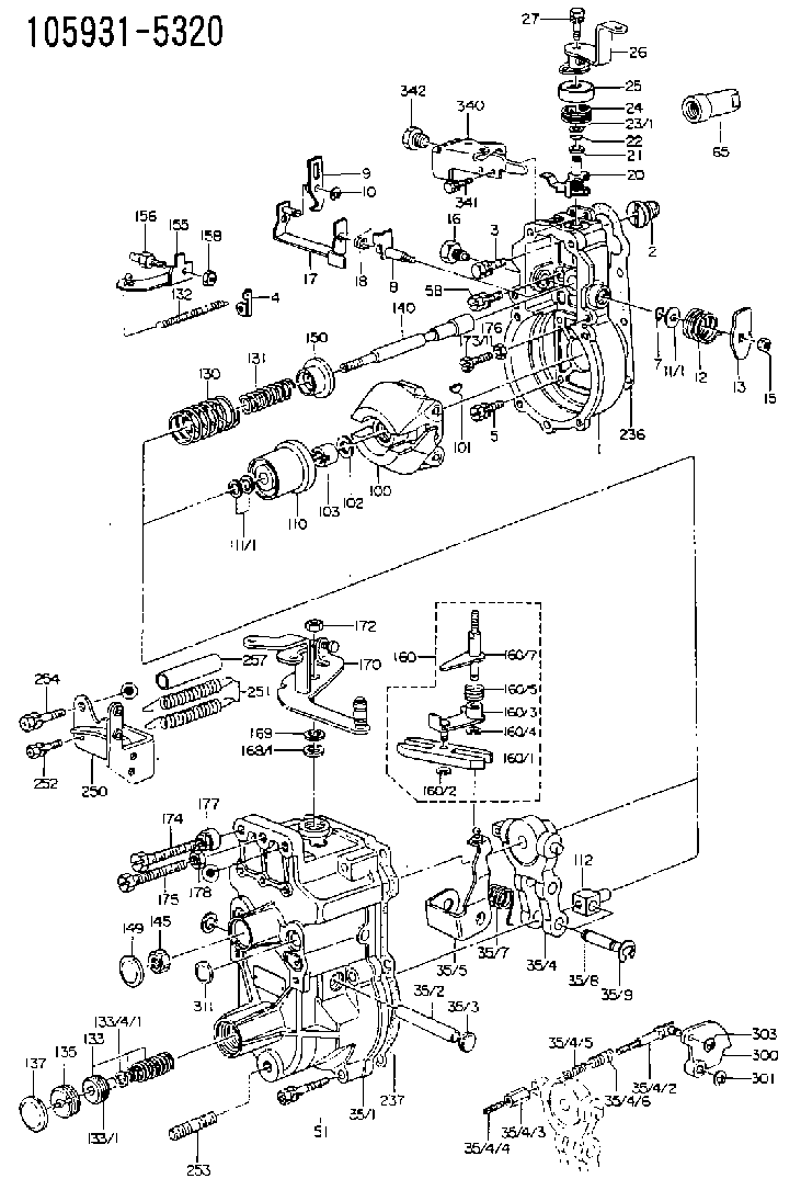
| 1. | [1] | 159200-4920 | GOVERNOR HOUSING |
| 2. | [1] | 154007-0200 | ADAPTOR |
| 3. | [1] | 020018-1840 | BLEEDER SCREW M8P1.25L18 |
| 4. | [1] | 159232-2620 | PLATE |
| 5. | [5] | 029010-6810 | BLEEDER SCREW |
| 5B. | [1] | 020106-1640 | BLEEDER SCREW M6P1.0L14 |
| 7. | [1] | 016530-1010 | O-RING |
| 8. | [1] | 159205-2321 | LEVER SHAFT |
| 9. | [1] | 159202-1802 | CONTROL LEVER |
| 10. | [1] | 016010-0810 | LOCKING WASHER |
| 11/1. | [0] | 029311-0220 | SHIM D18&10.3T0.2 |
| 11/1. | [0] | 029311-0230 | SHIM D18&10.3T0.5 |
| 11/1. | [0] | 029311-0430 | SHIM D18&10.3T0.30 |
| 11/1. | [0] | 029311-0440 | SHIM D18&10.3T0.40 |
| 11/1. | [0] | 029311-0450 | SHIM D18&10.3T0.25 |
| 11/1. | [0] | 029311-0460 | SHIM D18&10.3T0.35 |
| 11/1. | [0] | 139410-3300 | SHIM D18&10.3T0.6 |
| 11/1. | [0] | 139410-3400 | SHIM D18&10.3T0.8 |
| 11/1. | [0] | 139410-3500 | SHIM D18&10.3T0.9 |
| 12. | [1] | 159215-0000 | COILED SPRING |
| 13. | [1] | 159242-6601 | CONTROL LEVER |
| 15. | [1] | 013020-8040 | UNION NUT M8P1.25H7 |
| 16. | [1] | 159237-5200 | CAPSULE |
| 17. | [1] | 159202-1920 | CONTROL LEVER |
| 18. | [1] | 159215-0300 | COILED SPRING |
| 20. | [1] | 159242-0220 | CONTROL LEVER |
| 21. | [1] | 159242-0600 | BUSHING |
| 22. | [1] | 016530-1010 | O-RING |
| 23/1. | [0] | 029311-0220 | SHIM D18&10.3T0.2 |
| 23/1. | [0] | 029311-0230 | SHIM D18&10.3T0.5 |
| 23/1. | [0] | 029311-0430 | SHIM D18&10.3T0.30 |
| 23/1. | [0] | 029311-0440 | SHIM D18&10.3T0.40 |
| 23/1. | [0] | 029311-0450 | SHIM D18&10.3T0.25 |
| 23/1. | [0] | 029311-0460 | SHIM D18&10.3T0.35 |
| 23/1. | [0] | 139410-3300 | SHIM D18&10.3T0.6 |
| 23/1. | [0] | 139410-3400 | SHIM D18&10.3T0.8 |
| 23/1. | [0] | 139410-3500 | SHIM D18&10.3T0.9 |
| 24. | [1] | 159215-2000 | COILED SPRING |
| 25. | [1] | 159235-5800 | CAP |
| 26. | [1] | 159249-7120 | CONTROL LEVER |
| 27. | [1] | 020006-4040 | BLEEDER SCREW |
| 35. | [1] | 159251-3920 | GOVERNOR COVER |
| 35/1. | [1] | 159201-3422 | GOVERNOR COVER |
| 35/1/4. | [1] | 159230-0902 | BUSHING |
| 35/1/5. | [1] | 029621-0080 | PACKING RING |
| 35/2. | [1] | 159205-0400 | LEVER SHAFT |
| 35/3. | [2] | 159237-0200 | CAPSULE |
| 35/4. | [1] | 159253-0720 | TENSIONING LEVER |
| 35/4/1. | [1] | 159203-0720 | TENSIONING LEVER |
| 35/4/2. | [1] | 159204-5021 | RACK |
| 35/4/3. | [1] | 159233-0300 | UNION NUT |
| 35/4/4. | [1] | 159234-0300 | FLAT-HEAD SCREW |
| 35/4/5. | [1] | 159216-0000 | COILED SPRING |
| 35/4/6. | [1] | 159216-0100 | COILED SPRING |
| 35/5. | [1] | 159203-5720 | GUIDE LEVER |
| 35/7. | [1] | 159215-1701 | COILED SPRING |
| 35/8. | [1] | 159231-2000 | BEARING PIN |
| 35/9. | [2] | 016010-0610 | LOCKING WASHER |
| 51. | [7] | 020106-3840 | BLEEDER SCREW |
| 65. | [1] | 154050-1720 | STOPPING DEVICE |
| 100. | [1] | 154100-9520 | FLYWEIGHT ASSEMBLY |
| 101. | [1] | 025803-1610 | WOODRUFF KEY |
| 102. | [1] | 029321-2020 | LOCKING WASHER |
| 103. | [1] | 029231-2030 | UNION NUT |
| 110. | [1] | 154123-2320 | SLIDING PIECE |
| 111/1. | [0] | 029311-0010 | SHIM D14&10.1T0.2 |
| 111/1. | [0] | 029311-0180 | SHIM D14&10.1T0.3 |
| 111/1. | [0] | 029311-0190 | SHIM D14&10.1T0.40 |
| 111/1. | [0] | 029311-0210 | SHIM D14&10.1T1 |
| 111/1. | [0] | 139410-0000 | SHIM D14.0&10.1T0.5 |
| 111/1. | [0] | 139410-0100 | SHIM D14.0&10.1T1.5 |
| 111/1. | [0] | 139410-3000 | SHIM D14&10.1T2.0 |
| 111/1. | [0] | 139410-3100 | SHIM D14&10.1T3.0 |
| 111/1. | [0] | 139410-3200 | SHIM D14&10.1T4.0 |
| 112. | [1] | 159236-0200 | TERMINAL STUD |
| 130. | [1] | 159210-2700 | COILED SPRING |
| 131. | [1] | 159211-3000 | GOVERNOR SPRING |
| 132. | [1] | 159214-0000 | COILED SPRING |
| 133. | [1] | 159212-4720 | SPRING PACK |
| 133/1. | [1] | 159234-5602 | GUIDE SLEEVE |
| 133/2. | [1] | 159212-4700 | COILED SPRING |
| 133/3. | [1] | 159212-4600 | COILED SPRING |
| 133/4/1. | [0] | 029310-9240 | SHIM D11.9&9T0.1 |
| 133/4/1. | [0] | 029310-9250 | SHIM D11.9&9T0.2 |
| 133/4/1. | [0] | 029310-9260 | SHIM D11.9&9T0.25 |
| 133/4/1. | [0] | 029310-9270 | SHIM D11.9&9T1.0 |
| 133/4/1. | [0] | 139409-0100 | SHIM D11.9&9T0.3 |
| 133/4/1. | [0] | 139409-0200 | SHIM D11.9&9T0.5 |
| 133/4/1. | [0] | 139409-0300 | SHIM D11.5&9T0.8 |
| 135. | [1] | 159248-2700 | FLAT-HEAD SCREW |
| 137. | [1] | 159237-5300 | CAPSULE |
| 140. | [1] | 159205-2101 | LEVER SHAFT |
| 145. | [1] | 159233-5700 | UNION NUT |
| 149. | [1] | 159237-5400 | CAPSULE |
| 150. | [1] | 159235-5300 | SLOTTED WASHER |
| 155. | [1] | 159204-7720 | STRAP |
| 156. | [1] | 159233-5800 | BLEEDER SCREW |
| 158. | [1] | 013020-5240 | UNION NUT M5P0.8H4 |
| 160. | [1] | 159252-0821 | LEVER GROUP |
| 160/1. | [1] | 159202-2200 | CONTROL LEVER |
| 160/2. | [1] | 016010-0810 | LOCKING WASHER |
| 160/3. | [1] | 159202-2120 | CONTROL LEVER |
| 160/4. | [1] | 016010-0810 | LOCKING WASHER |
| 160/5. | [1] | 159215-2301 | COILED SPRING |
| 160/7. | [1] | 159205-2222 | LEVER SHAFT |
| 168/1. | [0] | 029311-0640 | SHIM D26.0&10.2T0.95 |
| 168/1. | [0] | 029311-0650 | SHIM D26.0&10.2T0.20 |
| 168/1. | [0] | 029311-0660 | SHIM D26.0&10.2T0.25 |
| 168/1. | [0] | 029311-0670 | SHIM D26.0&10.2T0.30 |
| 168/1. | [0] | 029311-0680 | SHIM D26.0&10.2T0.35 |
| 168/1. | [0] | 029311-0690 | SHIM D26.0&10.2T0.40 |
| 168/1. | [0] | 029311-0700 | SHIM D26.0&10.2T0.50 |
| 168/1. | [0] | 139410-1400 | SHIM D26&10.2T0.7 |
| 168/1. | [0] | 139410-1500 | SHIM D26&10.2T0.9 |
| 168/1. | [0] | 139410-1600 | SHIM D26&10.2T0.8 |
| 168/1. | [0] | 139410-2700 | SHIM D26&10.2T0.6 |
| 169. | [1] | 139410-2300 | SHIM |
| 170. | [1] | 159261-0420 | CONTROL LEVER |
| 172. | [1] | 013020-8040 | UNION NUT M8P1.25H7 |
| 173/1. | [1] | 139006-3500 | BLEEDER SCREW M6P1.0L33 |
| 173/1. | [1] | 139006-3700 | BLEEDER SCREW M6P1.0L34 |
| 173/1. | [1] | 139006-3800 | BLEEDER SCREW M6P1.0L35 |
| 173/1. | [1] | 139006-3900 | BLEEDER SCREW M6P1.0L36 |
| 173/1. | [1] | 139006-5300 | BLEEDER SCREW M6P1.0L31 |
| 173/1. | [1] | 139006-5400 | BLEEDER SCREW M6P1.0L32 |
| 173/1. | [1] | 155615-2500 | BLEEDER SCREW M6P1.0L37 |
| 174. | [1] | 154010-7200 | BLEEDER SCREW M8P1.25L62 |
| 175. | [1] | 154010-2200 | BLEEDER SCREW |
| 176. | [1] | 159225-8600 | UNION NUT |
| 177. | [1] | 154011-2300 | UNION NUT |
| 178. | [1] | 154011-2800 | UNION NUT |
| 236. | [1] | 154390-0000 | GASKET |
| 237. | [1] | 159238-3100 | GASKET |
| 250. | [1] | 159228-1520 | BRACKET |
| 251. | [2] | 159243-4300 | COILED SPRING |
| 252. | [2] | 020106-1240 | BLEEDER SCREW M6P1.0L12 |
| 253. | [1] | 139010-0000 | STUD |
| 254. | [1] | 020118-1840 | BLEEDER SCREW |
| 257. | [2] | 154156-1800 | TUBE |
| 300. | [1] | 159209-8500 | CAM PLATE |
| 301. | [1] | 016010-0840 | LOCKING WASHER |
| 303. | [1] | 016010-0540 | LOCKING WASHER |
| 311. | [1] | 159237-0200 | CAPSULE |
| 340. | [1] | 159228-1700 | BRACKET |
| 341. | [2] | 020104-1040 | BLEEDER SCREW |
| 342. | [1] | 159248-0200 | BLEEDER SCREW |
| 835S. | [1] | 154062-1900 | CAP D12L24 |
| 836S. | [1] | 154062-1700 | CAP D20L32 |
Cross reference number
Zexel num
Bosch num
Firm num
Name
105931-5320
ME723833 MITSUBISHI
GOVERNOR
K 14JK MECHANICAL GOVERNOR GOV RLD GOV
K 14JK MECHANICAL GOVERNOR GOV RLD GOV
Information:
Keep all parts clean from contaminants. Contaminants put into the system may cause rapid wear and shortened component life.
1. Drain the cooling system. 2. Loosen hose clamps (1) and (3). Disconnect hoses (2) and (4). 3. Support pump (5) and remove four bolts (6). 4. Remove elbow (7) and the gasket. The following steps are to install the water pump.5. Install a new gasket and elbow (7).6. Put the water pump (5) and elbow (7) in position and install four bolts (6).7. Put hoses (2) and (4) in position on elbow (7) and tighten the clamps (1) and (3).8. Fill the cooling system to the correct level. See the Maintenance Manual.Disassemble And Assemble Water Pump
Start By:a. remove water pump
Keep all parts clean from contaminants. Contaminants put into the system may cause rapid wear and shortened component life.
1. Remove bolt (15) and the washer. Remove bearing (12) and gear (10) as a unit.2. Use tooling (A), (C) and a press, and remove bearing (12) from gear (10).3. Remove snap ring (8) with tool (B).4. Remove two bolts (1), the washers, cover (14) and gasket (2) from water pump housing (18).5. Loosen bolt (13) approximately 6.4 mm (.25 in). Hit the bolt with a soft hammer to loosen impeller (16).6. Remove bolt (13), washer (11), impeller (16), spring (3) and seal assembly (4).7. Remove bearing (7) and shaft (9) as a unit.8. Use tooling (A), (C) and a press to remove bearing (7).9. Remove ceramic seal (5) and seal (17).10. Use tool (C) to remove lip-type seal (6). The following steps are for assembly of the water pump.11. Install hydrodynamic seal (6) in water pump housing (18) with tool (C). The lip of the seal must be toward the bearings. Put clean engine oil on the lip of the seal.12. Install shaft (9) in bearing (7) with a press.13. Install shaft (9) and bearing (7) as a unit in water pump housing (18).14. Install snap ring (8) with tool (B).
Clean water only is permitted for use as a lubricant for assembly. Do not damage or put hands on the wear surface of the carbon ring or the ceramic ring. Install the ceramic ring with the smoothest face of the ring toward the carbon seal assembly.
15. Put ceramic ring (5) in position in seal (17). Use hand pressure and tool (D) to install the ceramic ring.16. Remove spring (3) from seal assembly (4). Use hand pressure and tool (D) to install the seal assembly. Push seal assembly (4) on shaft (9) until it makes light contact with ceramic ring (5).17. Install spring (3) on seal assembly (4). Put impeller (16) in position on shaft (9), and install washer (11) and bolt (13). Tighten bolt (13) to a torque of 38.0 1.5 N m (28 1 lb ft).18. Put gasket (2) and cover (14) in position and install the two washers and bolts (1).19. Install bearing (12) on gear (10) with a press.20. Position gear (10) and bearing (12) as