Information governor
BOSCH
9 420 613 024
9420613024
ZEXEL
105931-5044
1059315044
ISUZU
1157701920
1157701920

Rating:
Scheme ###:
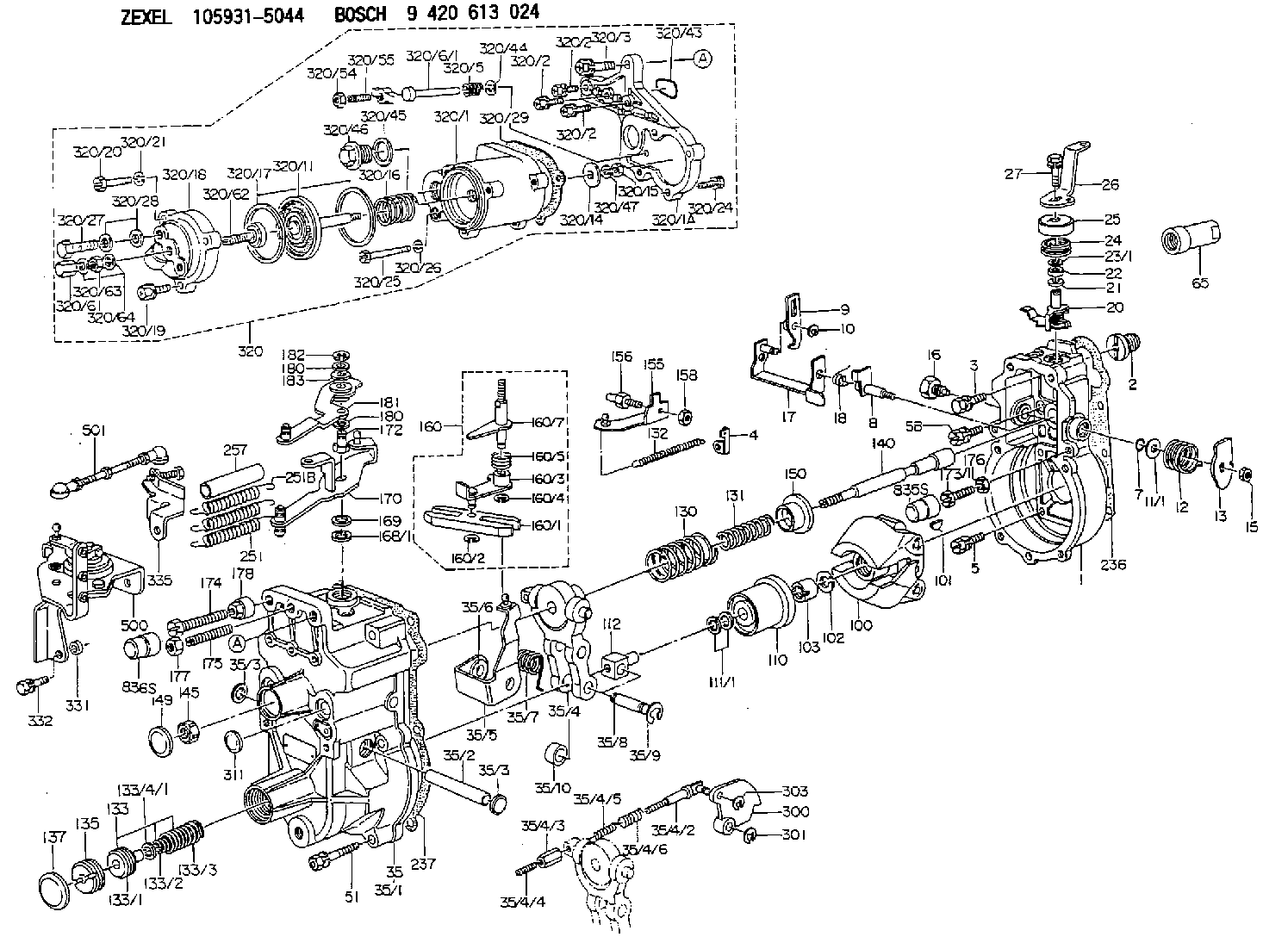
| 1. | [1] | 159200-5020 | GOVERNOR HOUSING |
| 2. | [1] | 154007-0200 | ADAPTOR |
| 3. | [1] | 020018-1840 | BLEEDER SCREW M8P1.25L18 |
| 4. | [1] | 159232-2620 | PLATE |
| 5. | [5] | 029010-6810 | BLEEDER SCREW |
| 5B. | [1] | 020106-1640 | BLEEDER SCREW M6P1.0L14 |
| 7. | [1] | 139710-0200 | O-RING |
| 8. | [1] | 159205-2321 | LEVER SHAFT |
| 9. | [1] | 159202-5101 | CONTROL LEVER |
| 10. | [1] | 016010-0810 | LOCKING WASHER |
| 11/1. | [0] | 029311-0220 | SHIM D18&10.3T0.2 |
| 11/1. | [0] | 029311-0230 | SHIM D18&10.3T0.5 |
| 11/1. | [0] | 029311-0430 | SHIM D18&10.3T0.30 |
| 11/1. | [0] | 029311-0440 | SHIM D18&10.3T0.40 |
| 11/1. | [0] | 029311-0450 | SHIM D18&10.3T0.25 |
| 11/1. | [0] | 029311-0460 | SHIM D18&10.3T0.35 |
| 11/1. | [0] | 139410-3300 | SHIM D18&10.3T0.6 |
| 11/1. | [0] | 139410-3400 | SHIM D18&10.3T0.8 |
| 11/1. | [0] | 139410-3500 | SHIM D18&10.3T0.9 |
| 12. | [1] | 159215-0000 | COILED SPRING |
| 13. | [1] | 159242-6601 | CONTROL LEVER |
| 15. | [1] | 013020-8040 | UNION NUT M8P1.25H7 |
| 16. | [1] | 159237-5500 | CAPSULE |
| 17. | [1] | 159202-5220 | CONTROL LEVER |
| 18. | [1] | 159215-0300 | COILED SPRING |
| 20. | [1] | 159242-0220 | CONTROL LEVER |
| 21. | [1] | 029311-0210 | SHIM D14&10.1T1 |
| 22. | [1] | 139610-0700 | PACKING RING |
| 23/1. | [0] | 139411-0700 | SHIM D22&11T0.7 |
| 23/1. | [0] | 153305-0100 | SHIM D22&11T0.5 |
| 23/1. | [0] | 153305-0200 | SHIM D22&11T0.4 |
| 23/1. | [0] | 153305-0300 | SHIM D22&11T0.3 |
| 23/1. | [0] | 153305-0400 | SHIM D22&11T0.25 |
| 23/1. | [0] | 153305-0500 | SHIM D22&11T1.0 |
| 23/1. | [0] | 153305-0600 | SHIM D22&11T1.1 |
| 23/1. | [0] | 153305-0700 | SHIM D22&11T2.0 |
| 23/1. | [0] | 153305-1300 | SHIM D22&11T0.951 |
| 23/1. | [0] | 153305-1400 | SHIM D22&11T0.95 |
| 24. | [1] | 159215-3400 | COILED SPRING |
| 25. | [1] | 159235-5800 | CAP |
| 26. | [1] | 159249-6400 | CONTROL LEVER |
| 27. | [1] | 020006-1640 | BLEEDER SCREW M6P1L16 4T |
| 35. | [1] | 159250-0220 | GOVERNOR COVER |
| 35/1. | [1] | 159201-8420 | GOVERNOR COVER |
| 35/2. | [1] | 159205-0400 | LEVER SHAFT |
| 35/3. | [2] | 159237-0200 | CAPSULE |
| 35/3. | [2] | 159237-0200 | CAPSULE |
| 35/4. | [1] | 159253-2320 | TENSIONING LEVER |
| 35/4/2. | [1] | 159204-5021 | RACK |
| 35/4/3. | [1] | 159233-0300 | UNION NUT |
| 35/4/4. | [1] | 159234-0300 | FLAT-HEAD SCREW |
| 35/4/5. | [1] | 159216-0000 | COILED SPRING |
| 35/4/6. | [1] | 159216-0100 | COILED SPRING |
| 35/5. | [1] | 159203-5320 | GUIDE LEVER |
| 35/6. | [2] | 159235-5000 | BUSHING |
| 35/7. | [1] | 159215-1701 | COILED SPRING |
| 35/8. | [1] | 159231-1300 | BEARING PIN |
| 35/9. | [2] | 016010-0610 | LOCKING WASHER |
| 35/10. | [1] | 159238-2900 | BUSHING |
| 51. | [7] | 020106-3840 | BLEEDER SCREW |
| 65. | [1] | 154050-1720 | STOPPING DEVICE |
| 100. | [1] | 154100-9520 | FLYWEIGHT ASSEMBLY |
| 101. | [1] | 025803-1610 | WOODRUFF KEY |
| 102. | [1] | 029321-2020 | LOCKING WASHER |
| 103. | [1] | 029231-2030 | UNION NUT |
| 110. | [1] | 154123-2320 | SLIDING PIECE |
| 111/1. | [0] | 029311-0010 | SHIM D14&10.1T0.2 |
| 111/1. | [0] | 029311-0180 | SHIM D14&10.1T0.3 |
| 111/1. | [0] | 029311-0190 | SHIM D14&10.1T0.40 |
| 111/1. | [0] | 029311-0210 | SHIM D14&10.1T1 |
| 111/1. | [0] | 139410-0000 | SHIM D14.0&10.1T0.5 |
| 111/1. | [0] | 139410-0100 | SHIM D14.0&10.1T1.5 |
| 111/1. | [0] | 139410-3000 | SHIM D14&10.1T2.0 |
| 111/1. | [0] | 139410-3100 | SHIM D14&10.1T3.0 |
| 111/1. | [0] | 139410-3200 | SHIM D14&10.1T4.0 |
| 112. | [1] | 159236-0200 | TERMINAL STUD |
| 130. | [1] | 159210-3200 | GOVERNOR SPRING |
| 131. | [1] | 159211-2200 | GOVERNOR SPRING |
| 132. | [1] | 159214-0000 | COILED SPRING |
| 133. | [1] | 159212-3520 | SPRING PACK |
| 133/1. | [1] | 159234-5602 | GUIDE SLEEVE |
| 133/2. | [1] | 159212-3300 | COILED SPRING |
| 133/3. | [1] | 159212-3500 | COILED SPRING |
| 133/4/1. | [0] | 029310-9240 | SHIM D11.9&9T0.1 |
| 133/4/1. | [0] | 029310-9250 | SHIM D11.9&9T0.2 |
| 133/4/1. | [0] | 029310-9260 | SHIM D11.9&9T0.25 |
| 133/4/1. | [0] | 029310-9270 | SHIM D11.9&9T1.0 |
| 133/4/1. | [0] | 139409-0100 | SHIM D11.9&9T0.3 |
| 133/4/1. | [0] | 139409-0200 | SHIM D11.9&9T0.5 |
| 133/4/1. | [0] | 139409-0300 | SHIM D11.5&9T0.8 |
| 135. | [1] | 159248-2700 | FLAT-HEAD SCREW |
| 137. | [1] | 159237-5300 | CAPSULE |
| 140. | [1] | 159205-2101 | LEVER SHAFT |
| 145. | [1] | 159233-5700 | UNION NUT |
| 149. | [1] | 159237-5400 | CAPSULE |
| 150. | [1] | 159235-5300 | SLOTTED WASHER |
| 155. | [1] | 159204-7720 | STRAP |
| 156. | [1] | 159233-0520 | BLEEDER SCREW |
| 158. | [1] | 013020-5240 | UNION NUT M5P0.8H4 |
| 160. | [1] | 159252-0821 | LEVER GROUP |
| 160/1. | [1] | 159202-2200 | CONTROL LEVER |
| 160/2. | [1] | 016010-0810 | LOCKING WASHER |
| 160/3. | [1] | 159202-2120 | CONTROL LEVER |
| 160/4. | [1] | 016010-0810 | LOCKING WASHER |
| 160/5. | [1] | 159215-2301 | COILED SPRING |
| 160/7. | [1] | 159205-2222 | LEVER SHAFT |
| 168/1. | [0] | 029311-0640 | SHIM D26.0&10.2T0.95 |
| 168/1. | [0] | 029311-0650 | SHIM D26.0&10.2T0.20 |
| 168/1. | [0] | 029311-0660 | SHIM D26.0&10.2T0.25 |
| 168/1. | [0] | 029311-0670 | SHIM D26.0&10.2T0.30 |
| 168/1. | [0] | 029311-0680 | SHIM D26.0&10.2T0.35 |
| 168/1. | [0] | 029311-0690 | SHIM D26.0&10.2T0.40 |
| 168/1. | [0] | 029311-0700 | SHIM D26.0&10.2T0.50 |
| 168/1. | [0] | 139410-1400 | SHIM D26&10.2T0.7 |
| 168/1. | [0] | 139410-1500 | SHIM D26&10.2T0.9 |
| 168/1. | [0] | 139410-1600 | SHIM D26&10.2T0.8 |
| 168/1. | [0] | 139410-2700 | SHIM D26&10.2T0.6 |
| 169. | [1] | 139410-2300 | SHIM |
| 170. | [1] | 159261-5620 | CONTROL LEVER |
| 172. | [1] | 159233-6100 | UNION NUT |
| 173/1. | [1] | 139006-3500 | BLEEDER SCREW M6P1.0L33 |
| 173/1. | [1] | 139006-3700 | BLEEDER SCREW M6P1.0L34 |
| 173/1. | [1] | 139006-3800 | BLEEDER SCREW M6P1.0L35 |
| 173/1. | [1] | 139006-3900 | BLEEDER SCREW M6P1.0L36 |
| 173/1. | [1] | 139006-5300 | BLEEDER SCREW M6P1.0L31 |
| 173/1. | [1] | 139006-5400 | BLEEDER SCREW M6P1.0L32 |
| 173/1. | [1] | 155615-2500 | BLEEDER SCREW M6P1.0L37 |
| 174. | [1] | 154010-7200 | BLEEDER SCREW M8P1.25L62 |
| 175. | [1] | 154010-0100 | FLAT-HEAD SCREW |
| 176. | [1] | 159225-8600 | UNION NUT |
| 177. | [1] | 154011-2300 | UNION NUT |
| 178. | [1] | 154011-0100 | HEXAGON NUT |
| 180. | [2] | 159235-6300 | PLAIN WASHER |
| 180. | [2] | 159235-6300 | PLAIN WASHER |
| 181. | [1] | 159260-8420 | CONTROL LEVER |
| 182. | [1] | 016010-0940 | LOCKING WASHER |
| 183. | [1] | 029301-0020 | PLAIN WASHER |
| 236. | [1] | 154390-0000 | GASKET |
| 237. | [1] | 159238-3100 | GASKET |
| 251. | [2] | 159243-7200 | COILED SPRING |
| 251B. | [1] | 159243-1200 | COILED SPRING |
| 257. | [3] | 154156-0500 | TUBE |
| 300. | [1] | 159209-8900 | CAM PLATE |
| 301. | [1] | 016010-0840 | LOCKING WASHER |
| 303. | [1] | 016010-0540 | LOCKING WASHER |
| 311. | [1] | 159237-0200 | CAPSULE |
| 320. | [1] | 154418-8520 | MANIFOLD-PRESSURE COMP. |
| 320/1. | [1] | 154408-9620 | DIAPHRAGM HOUSING |
| 320/1A. | [1] | 154418-3900 | SPACER BUSHING |
| 320/2. | [3] | 020106-2540 | BLEEDER SCREW M6P1L25 |
| 320/2. | [3] | 020106-2540 | BLEEDER SCREW M6P1L25 |
| 320/2. | [3] | 020106-2540 | BLEEDER SCREW M6P1L25 |
| 320/3. | [1] | 020118-3040 | BLEEDER SCREW |
| 320/5. | [1] | 159275-1400 | COILED SPRING |
| 320/6/1. | [1] | 159274-0120 | STOP PIN L125 |
| 320/6/1. | [1] | 159274-0220 | STOP PIN L127.50 |
| 320/6/1. | [1] | 159274-0320 | STOP PIN L128.00 |
| 320/6/1. | [1] | 159274-0420 | STOP PIN L127.00 |
| 320/6/1. | [1] | 159274-0520 | STOP PIN L126.00 |
| 320/6/1. | [1] | 159274-0620 | STOP PIN L129.00 |
| 320/6/1. | [1] | 159274-0720 | STOP PIN L128.50 |
| 320/6/1. | [1] | 159274-0820 | STOP PIN L125.50 |
| 320/6/1. | [1] | 159274-0920 | STOP PIN L126.50 |
| 320/6/1. | [1] | 159274-1120 | STOP PIN L119.5 |
| 320/6/1. | [1] | 159274-1220 | STOP PIN L120 |
| 320/6/1. | [1] | 159274-1320 | STOP PIN L120.5 |
| 320/6/1. | [1] | 159274-1420 | STOP PIN L121 |
| 320/6/1. | [1] | 159274-1520 | STOP PIN L121.5 |
| 320/6/1. | [1] | 159274-1620 | STOP PIN L122 |
| 320/6/1. | [1] | 159274-1720 | STOP PIN L122.5 |
| 320/6/1. | [1] | 159274-1820 | STOP PIN L123 |
| 320/6/1. | [1] | 159274-1920 | STOP PIN L123.5 |
| 320/6/1. | [1] | 159274-4220 | STOP PIN L129.5 |
| 320/6/1. | [1] | 159274-4320 | STOP PIN L130 |
| 320/6/1. | [1] | 159274-4420 | STOP PIN L130.5 |
| 320/6/1. | [1] | 159274-4520 | STOP PIN L131 |
| 320/6/1. | [1] | 159274-4620 | STOP PIN L131.5 |
| 320/6/1. | [1] | 159274-4720 | STOP PIN L132 |
| 320/6/1. | [1] | 159274-4820 | STOP PIN L132.5 |
| 320/6/1. | [1] | 159274-4920 | STOP PIN L133 |
| 320/6/1. | [1] | 159274-5020 | STOP PIN L133.5 |
| 320/11. | [1] | 154400-8521 | DIAPHRAGM |
| 320/14. | [1] | 154406-5500 | SLOTTED WASHER |
| 320/15. | [1] | 013030-6010 | UNION NUT |
| 320/16. | [1] | 154403-8200 | COILED SPRING |
| 320/17. | [2] | 154413-2600 | GASKET |
| 320/18. | [1] | 154404-5000 | COVER |
| 320/19. | [1] | 020106-2040 | BLEEDER SCREW M6P1L20 |
| 320/20. | [2] | 139006-7000 | BLEEDER SCREW |
| 320/21. | [2] | 014110-6440 | LOCKING WASHER |
| 320/24. | [3] | 020106-2240 | BLEEDER SCREW |
| 320/25. | [1] | 139006-1300 | BLEEDER SCREW M6P1L76 |
| 320/26. | [1] | 029320-6010 | LOCKING WASHER |
| 320/27. | [1] | 029731-0180 | EYE BOLT |
| 320/28. | [2] | 139510-0200 | GASKET |
| 320/29. | [1] | 154413-2800 | GASKET |
| 320/43. | [1] | 159226-4500 | SPACER RING |
| 320/44. | [1] | 014010-5140 | PLAIN WASHER D12&5.5T0.8 |
| 320/45. | [1] | 139518-0000 | GASKET |
| 320/46. | [1] | 154406-5800 | FLAT-HEAD SCREW |
| 320/47. | [1] | 014110-6440 | LOCKING WASHER |
| 320/54. | [1] | 013030-6040 | UNION NUT M6P1H3.6 |
| 320/55. | [1] | 154404-4800 | FLAT-HEAD SCREW |
| 320/61. | [1] | 154035-1600 | CAP NUT |
| 320/62. | [1] | 154404-4400 | FLAT-HEAD SCREW |
| 320/63. | [1] | 013030-6040 | UNION NUT M6P1H3.6 |
| 320/64. | [2] | 139506-0300 | GASKET |
| 331. | [1] | 159226-4800 | SPACER BUSHING |
| 332. | [1] | 020106-2840 | BLEEDER SCREW |
| 335. | [1] | 159228-4120 | BRACKET |
| 500. | [1] | 154600-9220 | LOAD SENSOR ASSY |
| 501. | [1] | 154604-7220 | STRAP |
| 835S. | [1] | 154062-1900 | CAP D12L24 |
| 836S. | [1] | 154062-1700 | CAP D20L32 |
Include in #1:
101603-4846
as GOVERNOR
Cross reference number
Zexel num
Bosch num
Firm num
Name
Information:
1. Remove bolts (1) and remove the oil pump pick-up and discharge tubes. 2. Remove two bolts (2) and remove the oil pump. The following step is for the installation of the oil pump.3. Position the oil pump and install and torque two bolts (2).4. Position the pick-up and discharge tubes and install bolts (1).End By:a. install oil panDisassemble And Assemble Oil Pump
Start By:a. remove oil pump 1. If necessary, remove the idler gear.2. Remove bolt (1) and remove relief valve spring (2) with relief valve (3).4. Use tooling (A) and remove input gear (4).
Before removing the input shaft and gear from the pump housing, be sure no burrs are on the input shaft. Burrs on the shaft may scratch and damage the pump housing.
5. Remove bolts (5) and separate the pump housing. Remove input shaft and gear (6) from the pump housing. Remove the driven gear from the housing. The following steps are for the assembly of the oil pump. Before pressing input gear (4) onto input shaft (6) be sure to install bolt (5), that is positioned under the input gear.6. Position input gear and shaft (6) in the pump housing. Press input gear (4) onto the input shaft until it is flush with the end of the shaft. Position the driven gear in the housing.7. Position the pump housings together. Install bolts (5). Install the idler gear if it was removed.8. Position relief valve spring (2), relief valve (3) and install bolt (1).End By:a. install oil pump