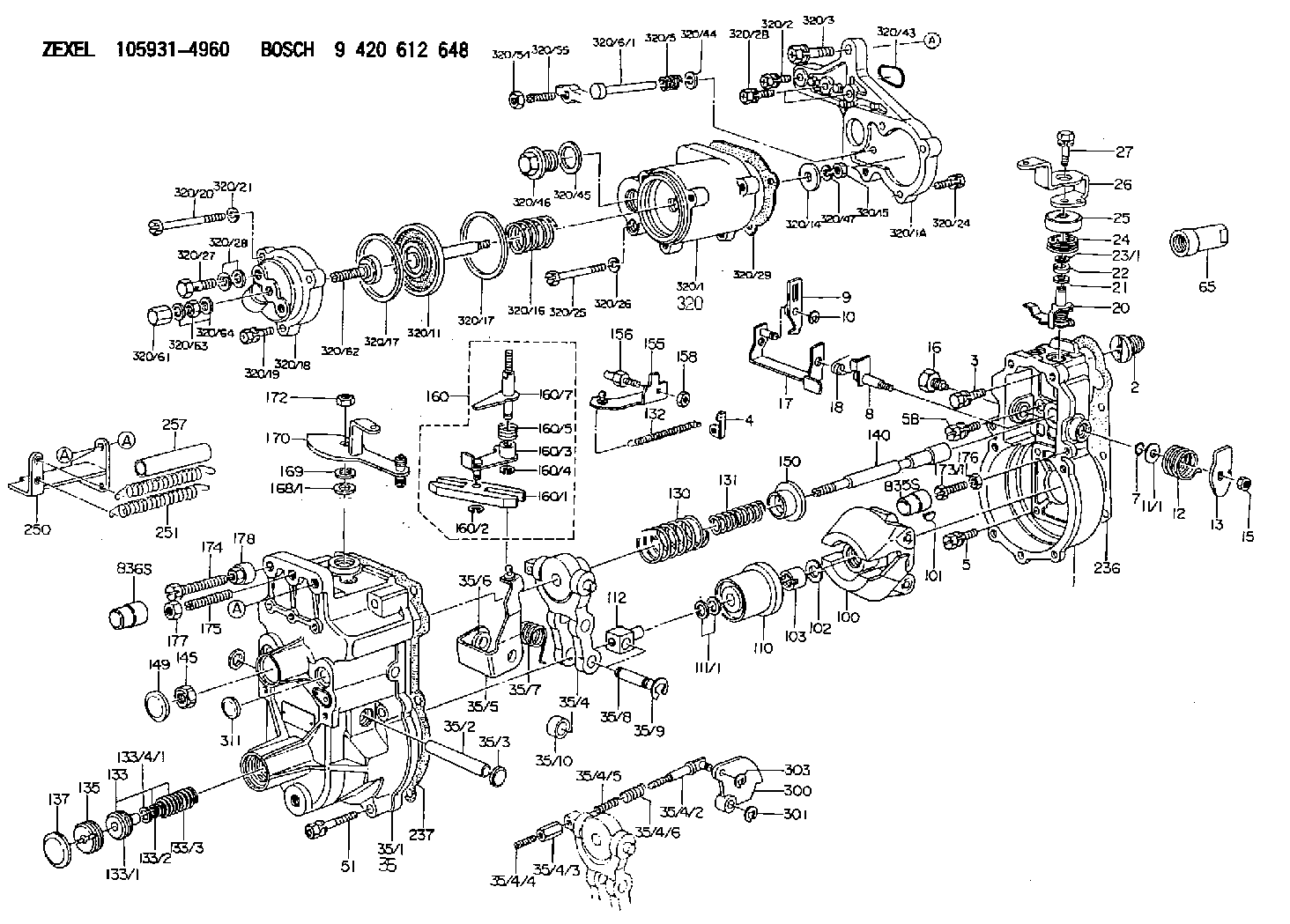
Information governor
BOSCH
9 420 612 648
9420612648
ZEXEL
105931-4960
1059314960
Rating:
Scheme ###:
| 1. | [1] | 159200-5020 | GOVERNOR HOUSING |
| 2. | [1] | 154007-0200 | ADAPTOR |
| 3. | [1] | 020018-1840 | BLEEDER SCREW M8P1.25L18 |
| 4. | [1] | 159232-2620 | PLATE |
| 5. | [5] | 029010-6810 | BLEEDER SCREW |
| 5B. | [1] | 020106-1640 | BLEEDER SCREW M6P1.0L14 |
| 7. | [1] | 139710-0200 | O-RING |
| 8. | [1] | 159205-2321 | LEVER SHAFT |
| 9. | [1] | 159202-5101 | CONTROL LEVER |
| 10. | [1] | 016010-0810 | LOCKING WASHER |
| 11/1. | [0] | 029311-0220 | SHIM D18&10.3T0.2 |
| 11/1. | [0] | 029311-0230 | SHIM D18&10.3T0.5 |
| 11/1. | [0] | 029311-0430 | SHIM D18&10.3T0.30 |
| 11/1. | [0] | 029311-0440 | SHIM D18&10.3T0.40 |
| 11/1. | [0] | 029311-0450 | SHIM D18&10.3T0.25 |
| 11/1. | [0] | 029311-0460 | SHIM D18&10.3T0.35 |
| 11/1. | [0] | 139410-3300 | SHIM D18&10.3T0.6 |
| 11/1. | [0] | 139410-3400 | SHIM D18&10.3T0.8 |
| 11/1. | [0] | 139410-3500 | SHIM D18&10.3T0.9 |
| 12. | [1] | 159215-0000 | COILED SPRING |
| 13. | [1] | 159242-6601 | CONTROL LEVER |
| 15. | [1] | 013020-8040 | UNION NUT M8P1.25H7 |
| 16. | [1] | 159237-5500 | CAPSULE |
| 17. | [1] | 159202-5220 | CONTROL LEVER |
| 18. | [1] | 159215-0300 | COILED SPRING |
| 20. | [1] | 159242-0220 | CONTROL LEVER |
| 21. | [1] | 029311-0210 | SHIM D14&10.1T1 |
| 22. | [1] | 139610-0700 | PACKING RING |
| 23/1. | [0] | 139411-0700 | SHIM D22&11T0.7 |
| 23/1. | [0] | 153305-0100 | SHIM D22&11T0.5 |
| 23/1. | [0] | 153305-0200 | SHIM D22&11T0.4 |
| 23/1. | [0] | 153305-0300 | SHIM D22&11T0.3 |
| 23/1. | [0] | 153305-0400 | SHIM D22&11T0.25 |
| 23/1. | [0] | 153305-0500 | SHIM D22&11T1.0 |
| 23/1. | [0] | 153305-0600 | SHIM D22&11T1.1 |
| 23/1. | [0] | 153305-0700 | SHIM D22&11T2.0 |
| 23/1. | [0] | 153305-1300 | SHIM D22&11T0.951 |
| 23/1. | [0] | 153305-1400 | SHIM D22&11T0.95 |
| 24. | [1] | 159215-3400 | COILED SPRING |
| 25. | [1] | 159235-5800 | CAP |
| 26. | [1] | 159249-2600 | CONTROL LEVER |
| 27. | [1] | 020006-1640 | BLEEDER SCREW M6P1L16 4T |
| 35. | [1] | 159250-0220 | GOVERNOR COVER |
| 35/1. | [1] | 159201-8420 | GOVERNOR COVER |
| 35/2. | [1] | 159205-0400 | LEVER SHAFT |
| 35/3. | [2] | 159237-0200 | CAPSULE |
| 35/4. | [1] | 159253-2320 | TENSIONING LEVER |
| 35/4/2. | [1] | 159204-5021 | RACK |
| 35/4/3. | [1] | 159233-0300 | UNION NUT |
| 35/4/4. | [1] | 159234-0300 | FLAT-HEAD SCREW |
| 35/4/5. | [1] | 159216-0000 | COILED SPRING |
| 35/4/6. | [1] | 159216-0100 | COILED SPRING |
| 35/5. | [1] | 159203-5320 | GUIDE LEVER |
| 35/6. | [2] | 159235-5000 | BUSHING |
| 35/7. | [1] | 159215-1701 | COILED SPRING |
| 35/8. | [1] | 159231-1300 | BEARING PIN |
| 35/9. | [2] | 016010-0610 | LOCKING WASHER |
| 35/10. | [1] | 159238-2900 | BUSHING |
| 51. | [7] | 020106-3840 | BLEEDER SCREW |
| 65. | [1] | 154050-1720 | STOPPING DEVICE |
| 100. | [1] | 154100-9520 | FLYWEIGHT ASSEMBLY |
| 101. | [1] | 025803-1610 | WOODRUFF KEY |
| 102. | [1] | 029321-2020 | LOCKING WASHER |
| 103. | [1] | 029231-2030 | UNION NUT |
| 110. | [1] | 154123-2320 | SLIDING PIECE |
| 111/1. | [0] | 029311-0010 | SHIM D14&10.1T0.2 |
| 111/1. | [0] | 029311-0180 | SHIM D14&10.1T0.3 |
| 111/1. | [0] | 029311-0190 | SHIM D14&10.1T0.40 |
| 111/1. | [0] | 029311-0210 | SHIM D14&10.1T1 |
| 111/1. | [0] | 139410-0000 | SHIM D14.0&10.1T0.5 |
| 111/1. | [0] | 139410-0100 | SHIM D14.0&10.1T1.5 |
| 111/1. | [0] | 139410-3000 | SHIM D14&10.1T2.0 |
| 111/1. | [0] | 139410-3100 | SHIM D14&10.1T3.0 |
| 111/1. | [0] | 139410-3200 | SHIM D14&10.1T4.0 |
| 112. | [1] | 159236-0200 | TERMINAL STUD |
| 130. | [1] | 159210-3200 | GOVERNOR SPRING |
| 131. | [1] | 159211-2200 | GOVERNOR SPRING |
| 132. | [1] | 159214-0000 | COILED SPRING |
| 133. | [1] | 159212-3520 | SPRING PACK |
| 133/1. | [1] | 159234-5602 | GUIDE SLEEVE |
| 133/2. | [1] | 159212-3300 | COILED SPRING |
| 133/3. | [1] | 159212-3500 | COILED SPRING |
| 133/4/1. | [0] | 029310-9240 | SHIM D11.9&9T0.1 |
| 133/4/1. | [0] | 029310-9250 | SHIM D11.9&9T0.2 |
| 133/4/1. | [0] | 029310-9260 | SHIM D11.9&9T0.25 |
| 133/4/1. | [0] | 029310-9270 | SHIM D11.9&9T1.0 |
| 133/4/1. | [0] | 139409-0100 | SHIM D11.9&9T0.3 |
| 133/4/1. | [0] | 139409-0200 | SHIM D11.9&9T0.5 |
| 133/4/1. | [0] | 139409-0300 | SHIM D11.5&9T0.8 |
| 135. | [1] | 159248-2700 | FLAT-HEAD SCREW |
| 137. | [1] | 159237-5300 | CAPSULE |
| 140. | [1] | 159205-2101 | LEVER SHAFT |
| 145. | [1] | 159233-5700 | UNION NUT |
| 149. | [1] | 159237-5400 | CAPSULE |
| 150. | [1] | 159235-5300 | SLOTTED WASHER |
| 155. | [1] | 159204-7720 | STRAP |
| 156. | [1] | 159233-0520 | BLEEDER SCREW |
| 158. | [1] | 013020-5240 | UNION NUT M5P0.8H4 |
| 160. | [1] | 159252-0821 | LEVER GROUP |
| 160/1. | [1] | 159202-2200 | CONTROL LEVER |
| 160/2. | [1] | 016010-0810 | LOCKING WASHER |
| 160/3. | [1] | 159202-2120 | CONTROL LEVER |
| 160/4. | [1] | 016010-0810 | LOCKING WASHER |
| 160/5. | [1] | 159215-2301 | COILED SPRING |
| 160/7. | [1] | 159205-2222 | LEVER SHAFT |
| 168/1. | [0] | 029311-0640 | SHIM D26.0&10.2T0.95 |
| 168/1. | [0] | 029311-0650 | SHIM D26.0&10.2T0.20 |
| 168/1. | [0] | 029311-0660 | SHIM D26.0&10.2T0.25 |
| 168/1. | [0] | 029311-0670 | SHIM D26.0&10.2T0.30 |
| 168/1. | [0] | 029311-0680 | SHIM D26.0&10.2T0.35 |
| 168/1. | [0] | 029311-0690 | SHIM D26.0&10.2T0.40 |
| 168/1. | [0] | 029311-0700 | SHIM D26.0&10.2T0.50 |
| 168/1. | [0] | 139410-1400 | SHIM D26&10.2T0.7 |
| 168/1. | [0] | 139410-1500 | SHIM D26&10.2T0.9 |
| 168/1. | [0] | 139410-1600 | SHIM D26&10.2T0.8 |
| 168/1. | [0] | 139410-2700 | SHIM D26&10.2T0.6 |
| 169. | [1] | 139410-2300 | SHIM |
| 170. | [1] | 159260-3820 | CONTROL LEVER |
| 172. | [1] | 013020-8040 | UNION NUT M8P1.25H7 |
| 173/1. | [1] | 139006-3500 | BLEEDER SCREW M6P1.0L33 |
| 173/1. | [1] | 139006-3700 | BLEEDER SCREW M6P1.0L34 |
| 173/1. | [1] | 139006-3800 | BLEEDER SCREW M6P1.0L35 |
| 173/1. | [1] | 139006-3900 | BLEEDER SCREW M6P1.0L36 |
| 173/1. | [1] | 139006-5300 | BLEEDER SCREW M6P1.0L31 |
| 173/1. | [1] | 139006-5400 | BLEEDER SCREW M6P1.0L32 |
| 173/1. | [1] | 155615-2500 | BLEEDER SCREW M6P1.0L37 |
| 174. | [1] | 154010-7200 | BLEEDER SCREW M8P1.25L62 |
| 175. | [1] | 154010-0100 | FLAT-HEAD SCREW |
| 176. | [1] | 159225-8600 | UNION NUT |
| 177. | [1] | 154011-2300 | UNION NUT |
| 178. | [1] | 154011-0100 | HEXAGON NUT |
| 236. | [1] | 154390-0000 | GASKET |
| 237. | [1] | 159238-3100 | GASKET |
| 250. | [1] | 159226-9820 | BRACKET |
| 251. | [2] | 159243-1200 | COILED SPRING |
| 257. | [2] | 154156-0500 | TUBE |
| 300. | [1] | 159209-9400 | CAM PLATE |
| 301. | [1] | 016010-0840 | LOCKING WASHER |
| 303. | [1] | 016010-0540 | LOCKING WASHER |
| 311. | [1] | 159237-0200 | CAPSULE |
| 320. | [1] | 154418-8120 | MANIFOLD-PRESSURE COMP. |
| 320/1. | [1] | 154408-9620 | DIAPHRAGM HOUSING |
| 320/1A. | [1] | 154418-3900 | SPACER BUSHING |
| 320/2. | [1] | 020106-2040 | BLEEDER SCREW M6P1L20 |
| 320/2B. | [2] | 020106-2540 | BLEEDER SCREW M6P1L25 |
| 320/3. | [1] | 020118-3040 | BLEEDER SCREW |
| 320/5. | [1] | 159275-1400 | COILED SPRING |
| 320/6/1. | [1] | 159274-0120 | STOP PIN L125 |
| 320/6/1. | [1] | 159274-0220 | STOP PIN L127.50 |
| 320/6/1. | [1] | 159274-0320 | STOP PIN L128.00 |
| 320/6/1. | [1] | 159274-0420 | STOP PIN L127.00 |
| 320/6/1. | [1] | 159274-0520 | STOP PIN L126.00 |
| 320/6/1. | [1] | 159274-0620 | STOP PIN L129.00 |
| 320/6/1. | [1] | 159274-0720 | STOP PIN L128.50 |
| 320/6/1. | [1] | 159274-0820 | STOP PIN L125.50 |
| 320/6/1. | [1] | 159274-0920 | STOP PIN L126.50 |
| 320/6/1. | [1] | 159274-1120 | STOP PIN L119.5 |
| 320/6/1. | [1] | 159274-1220 | STOP PIN L120 |
| 320/6/1. | [1] | 159274-1320 | STOP PIN L120.5 |
| 320/6/1. | [1] | 159274-1420 | STOP PIN L121 |
| 320/6/1. | [1] | 159274-1520 | STOP PIN L121.5 |
| 320/6/1. | [1] | 159274-1620 | STOP PIN L122 |
| 320/6/1. | [1] | 159274-1720 | STOP PIN L122.5 |
| 320/6/1. | [1] | 159274-1820 | STOP PIN L123 |
| 320/6/1. | [1] | 159274-1920 | STOP PIN L123.5 |
| 320/6/1. | [1] | 159274-4220 | STOP PIN L129.5 |
| 320/6/1. | [1] | 159274-4320 | STOP PIN L130 |
| 320/6/1. | [1] | 159274-4420 | STOP PIN L130.5 |
| 320/6/1. | [1] | 159274-4520 | STOP PIN L131 |
| 320/6/1. | [1] | 159274-4620 | STOP PIN L131.5 |
| 320/6/1. | [1] | 159274-4720 | STOP PIN L132 |
| 320/6/1. | [1] | 159274-4820 | STOP PIN L132.5 |
| 320/6/1. | [1] | 159274-4920 | STOP PIN L133 |
| 320/6/1. | [1] | 159274-5020 | STOP PIN L133.5 |
| 320/11. | [1] | 154400-8521 | DIAPHRAGM |
| 320/14. | [1] | 154406-5500 | SLOTTED WASHER |
| 320/15. | [1] | 013030-6010 | UNION NUT |
| 320/16. | [1] | 154403-8200 | COILED SPRING |
| 320/17. | [2] | 154413-2600 | GASKET |
| 320/17. | [2] | 154413-2600 | GASKET |
| 320/18. | [1] | 154404-5000 | COVER |
| 320/19. | [1] | 020106-2040 | BLEEDER SCREW M6P1L20 |
| 320/20. | [2] | 139006-7000 | BLEEDER SCREW |
| 320/21. | [2] | 014110-6440 | LOCKING WASHER |
| 320/24. | [3] | 020106-2240 | BLEEDER SCREW |
| 320/25. | [1] | 139006-1300 | BLEEDER SCREW M6P1L76 |
| 320/26. | [1] | 029320-6010 | LOCKING WASHER |
| 320/27. | [1] | 029731-0180 | EYE BOLT |
| 320/28. | [2] | 139510-0200 | GASKET |
| 320/29. | [1] | 154413-2800 | GASKET |
| 320/43. | [1] | 159226-4500 | SPACER RING |
| 320/44. | [1] | 014010-5140 | PLAIN WASHER D12&5.5T0.8 |
| 320/45. | [1] | 139518-0000 | GASKET |
| 320/46. | [1] | 154406-5800 | FLAT-HEAD SCREW |
| 320/47. | [1] | 014110-6440 | LOCKING WASHER |
| 320/54. | [1] | 013030-6040 | UNION NUT M6P1H3.6 |
| 320/55. | [1] | 154404-4800 | FLAT-HEAD SCREW |
| 320/61. | [1] | 154035-1600 | CAP NUT |
| 320/62. | [1] | 154404-4400 | FLAT-HEAD SCREW |
| 320/63. | [1] | 013030-6040 | UNION NUT M6P1H3.6 |
| 320/64. | [2] | 139506-0300 | GASKET |
| 835S. | [1] | 154062-1900 | CAP D12L24 |
| 836S. | [1] | 154062-1700 | CAP D20L32 |
Cross reference number
Zexel num
Bosch num
Firm num
Name
Information:
T-T-T Procedure
A torque-turn-tighten (T-T-T) procedure is used in many specifications and instructions.1. Clean the bolt and nut threads.2. Put lubrication of the threads and the seat face of the bolt and nut.3. Turn the bolt or the nut tight according to the torque specification.4. Put a location mark on the part and on the bolt head or nut.5. Turn the bolt or the nut tighter the amount of degrees according to the specifications The side of a nut or bolt head can be used for reference if a mark can not be put on. Torque Wrench Extension
When a torque wrench extension is used with a torque wrench, the torque indication on the torque wrench will be less than the real torque.
(E) Torque wrench drive axis-to-torque wrench extension drive axis. (W) Mark on handle-to-torque wrench drive axis.1. Put a mark on the handle. Measure the handle from the mark to the axis of the torque wrench drive (W).2. Measure the torque wrench extension from the torque wrench drive to the axis of the torque wrench extension drive (E).3. To get correct torque indication (TI) when the real torque (RT) is known: Example: W = 304.8 mm (12 in); E = 65.0 mm (2.56 in); RT (from specifications) = 17 N m (125 lb ft). 4. Hold the torque wrench handle with the longest finger of the hand over the mark on the handle to get the real torque (RT) with low torque indication (TI) on the torque wrench.Locks
Flat metal locks must be installed properly to be effective. Bend one end of the lock around the edge of the part. Bend the other end against one flat surface of the nut of bolt head.Always install new locks in components which house moving parts.If lockwashers are installed on housings made of aluminum, use a flat washer between the lockwasher and the housing. Lines And Wires
When removing or disconnecting a group of lines or wires, tag each one to assure proper assembly.Lubrication
Where applicable, fill the compartments of the components serviced with the amount, type and grade of lubricant recommended in the Operation Maintenance Manual.Rust Preventive Compound
Clean the rust preventive compound from all machined surfaces of new parts before installing the part.Shims
When shims are removed, tie them together and identify them as to location. Keep shims clean and flat until they are reinstalled.Bearings
Anti-Friction Bearings
When an anti-friction bearing is removed, cover it to keep out dirt and abrasives. Wash the bearings in nonflammable cleaning solution and allow them to drain dry. The bearings may be dried with compressed air, but DO NOT SPIN THE BEARING. Discard the bearings if the races and balls or rollers are pitted, scored or burned. If the bearing is serviceable, coat it with oil and wrap it in clean paper. DO NOT unwrap new bearings until time of installation.The life of an anti-friction bearing will be shortened if not properly lubricated.Double Row, Tapered Roller
Double row, tapered roller bearings are precision fit during manufacture and the components are not interchangeable.