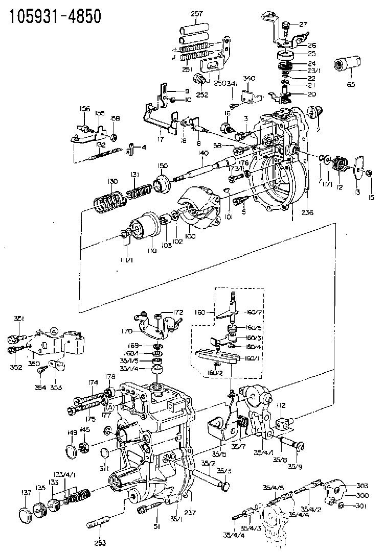
Information governor
BOSCH
F 019 Z1E 491
f019z1e491
ZEXEL
105931-4850
1059314850
MITSUBISHI
ME723294
me723294

Rating:
Scheme ###:
| 1. | [1] | 159200-4920 | GOVERNOR HOUSING |
| 2. | [1] | 154007-0200 | ADAPTOR |
| 3. | [1] | 020018-1840 | BLEEDER SCREW M8P1.25L18 |
| 4. | [1] | 159232-0201 | PLATE |
| 5. | [5] | 029010-6810 | BLEEDER SCREW |
| 5B. | [1] | 020106-1640 | BLEEDER SCREW M6P1.0L14 |
| 7. | [1] | 016530-1010 | O-RING |
| 8. | [1] | 159205-2321 | LEVER SHAFT |
| 9. | [1] | 159202-1802 | CONTROL LEVER |
| 10. | [1] | 016010-0810 | LOCKING WASHER |
| 11/1. | [0] | 029311-0220 | SHIM D18&10.3T0.2 |
| 11/1. | [0] | 029311-0230 | SHIM D18&10.3T0.5 |
| 11/1. | [0] | 029311-0430 | SHIM D18&10.3T0.30 |
| 11/1. | [0] | 029311-0440 | SHIM D18&10.3T0.40 |
| 11/1. | [0] | 029311-0450 | SHIM D18&10.3T0.25 |
| 11/1. | [0] | 029311-0460 | SHIM D18&10.3T0.35 |
| 11/1. | [0] | 139410-3300 | SHIM D18&10.3T0.6 |
| 11/1. | [0] | 139410-3400 | SHIM D18&10.3T0.8 |
| 11/1. | [0] | 139410-3500 | SHIM D18&10.3T0.9 |
| 12. | [1] | 159215-0000 | COILED SPRING |
| 13. | [1] | 159242-6601 | CONTROL LEVER |
| 15. | [1] | 013020-8040 | UNION NUT M8P1.25H7 |
| 16. | [1] | 159237-5200 | CAPSULE |
| 17. | [1] | 159202-1920 | CONTROL LEVER |
| 18. | [1] | 159215-0300 | COILED SPRING |
| 20. | [1] | 159242-0220 | CONTROL LEVER |
| 21. | [1] | 159242-0600 | BUSHING |
| 22. | [1] | 016530-1010 | O-RING |
| 23/1. | [0] | 029311-0220 | SHIM D18&10.3T0.2 |
| 23/1. | [0] | 029311-0230 | SHIM D18&10.3T0.5 |
| 23/1. | [0] | 029311-0430 | SHIM D18&10.3T0.30 |
| 23/1. | [0] | 029311-0440 | SHIM D18&10.3T0.40 |
| 23/1. | [0] | 029311-0450 | SHIM D18&10.3T0.25 |
| 23/1. | [0] | 029311-0460 | SHIM D18&10.3T0.35 |
| 23/1. | [0] | 139410-3300 | SHIM D18&10.3T0.6 |
| 23/1. | [0] | 139410-3400 | SHIM D18&10.3T0.8 |
| 23/1. | [0] | 139410-3500 | SHIM D18&10.3T0.9 |
| 24. | [1] | 159215-2000 | COILED SPRING |
| 25. | [1] | 159235-5800 | CAP |
| 26. | [1] | 159249-5520 | CONTROL LEVER |
| 27. | [1] | 020006-1640 | BLEEDER SCREW M6P1L16 4T |
| 35. | [1] | 159251-3920 | GOVERNOR COVER |
| 35/1. | [1] | 159201-3422 | GOVERNOR COVER |
| 35/1/4. | [1] | 159230-0902 | BUSHING |
| 35/1/5. | [1] | 029621-0080 | PACKING RING |
| 35/2. | [1] | 159205-0400 | LEVER SHAFT |
| 35/3. | [2] | 159237-0200 | CAPSULE |
| 35/4. | [1] | 159253-0720 | TENSIONING LEVER |
| 35/4/1. | [1] | 159203-0720 | TENSIONING LEVER |
| 35/4/2. | [1] | 159204-5021 | RACK |
| 35/4/3. | [1] | 159233-0300 | UNION NUT |
| 35/4/4. | [1] | 159234-0300 | FLAT-HEAD SCREW |
| 35/4/5. | [1] | 159216-0000 | COILED SPRING |
| 35/4/6. | [1] | 159216-0100 | COILED SPRING |
| 35/5. | [1] | 159203-5720 | GUIDE LEVER |
| 35/7. | [1] | 159215-1701 | COILED SPRING |
| 35/8. | [1] | 159231-2000 | BEARING PIN |
| 35/9. | [2] | 016010-0610 | LOCKING WASHER |
| 51. | [6] | 020106-3840 | BLEEDER SCREW |
| 51B. | [1] | 020106-4040 | BLEEDER SCREW |
| 65. | [1] | 154050-1720 | STOPPING DEVICE |
| 100. | [1] | 154100-9520 | FLYWEIGHT ASSEMBLY |
| 101. | [1] | 025803-1610 | WOODRUFF KEY |
| 102. | [1] | 029321-2020 | LOCKING WASHER |
| 103. | [1] | 029231-2030 | UNION NUT |
| 110. | [1] | 154123-2320 | SLIDING PIECE |
| 111/1. | [0] | 029311-0010 | SHIM D14&10.1T0.2 |
| 111/1. | [0] | 029311-0180 | SHIM D14&10.1T0.3 |
| 111/1. | [0] | 029311-0190 | SHIM D14&10.1T0.40 |
| 111/1. | [0] | 029311-0210 | SHIM D14&10.1T1 |
| 111/1. | [0] | 139410-0000 | SHIM D14.0&10.1T0.5 |
| 111/1. | [0] | 139410-0100 | SHIM D14.0&10.1T1.5 |
| 111/1. | [0] | 139410-3000 | SHIM D14&10.1T2.0 |
| 111/1. | [0] | 139410-3100 | SHIM D14&10.1T3.0 |
| 111/1. | [0] | 139410-3200 | SHIM D14&10.1T4.0 |
| 112. | [1] | 159236-0200 | TERMINAL STUD |
| 130. | [1] | 159210-2700 | COILED SPRING |
| 131. | [1] | 159211-3000 | GOVERNOR SPRING |
| 132. | [1] | 159214-0000 | COILED SPRING |
| 133. | [1] | 159212-4720 | SPRING PACK |
| 133/1. | [1] | 159234-5602 | GUIDE SLEEVE |
| 133/2. | [1] | 159212-4700 | COILED SPRING |
| 133/3. | [1] | 159212-4600 | COILED SPRING |
| 133/4/1. | [0] | 029310-9240 | SHIM D11.9&9T0.1 |
| 133/4/1. | [0] | 029310-9250 | SHIM D11.9&9T0.2 |
| 133/4/1. | [0] | 029310-9260 | SHIM D11.9&9T0.25 |
| 133/4/1. | [0] | 029310-9270 | SHIM D11.9&9T1.0 |
| 133/4/1. | [0] | 139409-0100 | SHIM D11.9&9T0.3 |
| 133/4/1. | [0] | 139409-0200 | SHIM D11.9&9T0.5 |
| 133/4/1. | [0] | 139409-0300 | SHIM D11.5&9T0.8 |
| 135. | [1] | 159248-2700 | FLAT-HEAD SCREW |
| 137. | [1] | 159237-5300 | CAPSULE |
| 140. | [1] | 159205-2101 | LEVER SHAFT |
| 145. | [1] | 159233-5700 | UNION NUT |
| 149. | [1] | 159237-5400 | CAPSULE |
| 150. | [1] | 159235-5300 | SLOTTED WASHER |
| 155. | [1] | 159204-5120 | STRAP |
| 156. | [1] | 159233-5800 | BLEEDER SCREW |
| 158. | [1] | 013020-5240 | UNION NUT M5P0.8H4 |
| 160. | [1] | 159252-0821 | LEVER GROUP |
| 160/1. | [1] | 159202-2200 | CONTROL LEVER |
| 160/2. | [1] | 016010-0810 | LOCKING WASHER |
| 160/3. | [1] | 159202-2120 | CONTROL LEVER |
| 160/4. | [1] | 016010-0810 | LOCKING WASHER |
| 160/5. | [1] | 159215-2301 | COILED SPRING |
| 160/7. | [1] | 159205-2222 | LEVER SHAFT |
| 168/1. | [0] | 029311-0640 | SHIM D26.0&10.2T0.95 |
| 168/1. | [0] | 029311-0650 | SHIM D26.0&10.2T0.20 |
| 168/1. | [0] | 029311-0660 | SHIM D26.0&10.2T0.25 |
| 168/1. | [0] | 029311-0670 | SHIM D26.0&10.2T0.30 |
| 168/1. | [0] | 029311-0680 | SHIM D26.0&10.2T0.35 |
| 168/1. | [0] | 029311-0690 | SHIM D26.0&10.2T0.40 |
| 168/1. | [0] | 029311-0700 | SHIM D26.0&10.2T0.50 |
| 168/1. | [0] | 139410-1400 | SHIM D26&10.2T0.7 |
| 168/1. | [0] | 139410-1500 | SHIM D26&10.2T0.9 |
| 168/1. | [0] | 139410-1600 | SHIM D26&10.2T0.8 |
| 168/1. | [0] | 139410-2700 | SHIM D26&10.2T0.6 |
| 169. | [1] | 139410-2300 | SHIM |
| 170. | [1] | 159260-6620 | CONTROL LEVER |
| 172. | [1] | 013020-8040 | UNION NUT M8P1.25H7 |
| 173/1. | [1] | 139006-3500 | BLEEDER SCREW M6P1.0L33 |
| 173/1. | [1] | 139006-3700 | BLEEDER SCREW M6P1.0L34 |
| 173/1. | [1] | 139006-3800 | BLEEDER SCREW M6P1.0L35 |
| 173/1. | [1] | 139006-3900 | BLEEDER SCREW M6P1.0L36 |
| 173/1. | [1] | 139006-5300 | BLEEDER SCREW M6P1.0L31 |
| 173/1. | [1] | 139006-5400 | BLEEDER SCREW M6P1.0L32 |
| 173/1. | [1] | 155615-2500 | BLEEDER SCREW M6P1.0L37 |
| 174. | [1] | 154010-7200 | BLEEDER SCREW M8P1.25L62 |
| 175. | [1] | 154010-2900 | BLEEDER SCREW |
| 176. | [1] | 159225-8600 | UNION NUT |
| 177. | [1] | 154011-2300 | UNION NUT |
| 178. | [1] | 154011-0100 | HEXAGON NUT |
| 236. | [1] | 154390-0000 | GASKET |
| 237. | [1] | 159238-3100 | GASKET |
| 250. | [1] | 159227-8020 | BRACKET |
| 251. | [2] | 159243-3800 | COILED SPRING |
| 252. | [1] | 159248-0200 | BLEEDER SCREW |
| 253. | [1] | 139010-0000 | STUD |
| 257. | [2] | 154156-0700 | TUBE |
| 300. | [1] | 159209-8500 | CAM PLATE |
| 301. | [1] | 016010-0840 | LOCKING WASHER |
| 303. | [1] | 016010-0540 | LOCKING WASHER |
| 311. | [1] | 159237-0200 | CAPSULE |
| 340. | [1] | 159245-8300 | PLATE |
| 341. | [2] | 020104-1040 | BLEEDER SCREW |
| 350. | [1] | 159227-7800 | BRACKET |
| 351. | [1] | 020118-1440 | BLEEDER SCREW |
| 352. | [2] | 020106-1240 | BLEEDER SCREW M6P1.0L12 |
| 353. | [1] | 159245-8620 | PLATE |
| 354. | [1] | 020106-0840 | BLEEDER SCREW |
Include in #1:
101606-1640
as GOVERNOR
Cross reference number
Zexel num
Bosch num
Firm num
Name
Information:
Start By:a. remove timing gear cover 1. Remove bolt (1) and washer that fastens the weight assembly (2).
Weight assembly must have support during removal to prevent damage to components.
2. Install tooling (A) and remove the weight assembly.Install Automatic Timing Advance Unit
1. Install washer and bolt (1). With the fuel pump housing cover removed, turn the fuel pump camshaft in the direction of engine rotation until tool (A) can be installed in the notch of the camshaft. 2. To time the fuel injection pump to the engine with the front timing cover removed, follow Steps 3 and 4. With the timing cover installed, see Steps 6 and 7. No. 1 piston at top center (TC) on the compression stroke is the starting point for all timing procedures. The engine is seen from the flywheel end when direction of crankshaft rotation is given.3. Turn the crankshaft counterclockwise until the "C" on the crankshaft and camshaft and camshaft gears are in alignment. 4. Remove the plug and install tool (B) in the flywheel housing.5. To find top center compression stroke for No. 1 piston, turn the flywheel clockwise (opposite of engine rotation) approximately 30°. This procedure is to remove all end play from timing gears.6. Turn the flywheel counterclockwise (direction of engine rotation) until tool (B) can be installed in the flywheel. The piston is at top center. If you go past the bolt hole you must start over again. To see if the No. 1 piston is on the compression stroke, remove the breather assembly from the valve cover and look at the valves of the No. 1 cylinder. The valves will be closed if No. 1 cylinder is on the compression stroke. You must be able to move the rocker arms up and down with your hand.7. If NO. 1 piston is not on the compression stroke, remove tooling (B) and turn the flywheel 360° counterclockwise. Install tooling (B). The No. 1 piston is now at top center on the compression stroke.8. With tooling (A) and (B) installed in position, install the timing advance weight assembly on the fuel pump camshaft. 9. Install tooling (C) on the weight assembly. While a constant torque on drive gear on 68 N m (50 lb ft) is held, tighten the bolt that fastens the weight assembly to fuel pump camshaft to a torque of 270 25 N m (200 18 lb ft).10. Remove tooling (A), (B) and (C).End By:a. install timing gear coverDisassemble And Assemble Automatic Timing Unit
Start By:a. remove automatic timing advance unit
Keep all parts clean from contaminants. Contaminants put into the system may cause rapid wear and shortened component life.
1. Remove two screws (1) and plate (2).
The weights are held on position with two springs for each weight under compression. Carefully remove weights and springs to prevent possible injury.
2. Remove springs (4) and (5), weight (3) and slide (6) from each side of assembly. 3. If necessary, remove gear (7). Remove seals (11) and (10). The following steps