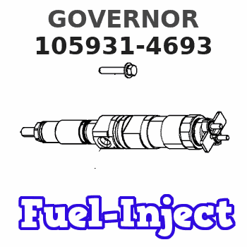
Information governor
BOSCH
9 420 611 306
9420611306
ZEXEL
105931-4693
1059314693
Rating:
Scheme ###:
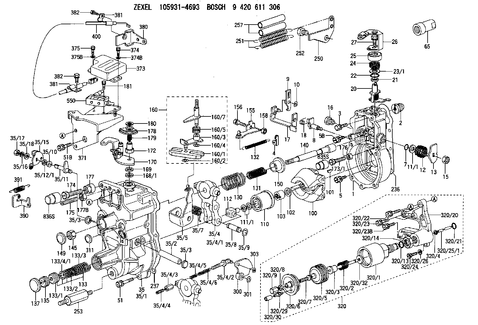
| 1. | [1] | 159200-3720 | GOVERNOR HOUSING |
| 2. | [1] | 154007-0200 | ADAPTOR |
| 3. | [1] | 020018-1840 | BLEEDER SCREW M8P1.25L18 |
| 4. | [1] | 159232-2620 | PLATE |
| 5. | [5] | 029010-6810 | BLEEDER SCREW |
| 5B. | [1] | 020106-1640 | BLEEDER SCREW M6P1.0L14 |
| 7. | [1] | 016530-1010 | O-RING |
| 8. | [1] | 159205-2321 | LEVER SHAFT |
| 9. | [1] | 159202-1802 | CONTROL LEVER |
| 10. | [1] | 016010-0810 | LOCKING WASHER |
| 11/1. | [0] | 029311-0220 | SHIM D18&10.3T0.2 |
| 11/1. | [0] | 029311-0230 | SHIM D18&10.3T0.5 |
| 11/1. | [0] | 029311-0430 | SHIM D18&10.3T0.30 |
| 11/1. | [0] | 029311-0440 | SHIM D18&10.3T0.40 |
| 11/1. | [0] | 029311-0450 | SHIM D18&10.3T0.25 |
| 11/1. | [0] | 029311-0460 | SHIM D18&10.3T0.35 |
| 11/1. | [0] | 139410-3300 | SHIM D18&10.3T0.6 |
| 11/1. | [0] | 139410-3400 | SHIM D18&10.3T0.8 |
| 11/1. | [0] | 139410-3500 | SHIM D18&10.3T0.9 |
| 12. | [1] | 159215-0000 | COILED SPRING |
| 13. | [1] | 159242-6601 | CONTROL LEVER |
| 15. | [1] | 013020-8040 | UNION NUT M8P1.25H7 |
| 16. | [1] | 159237-5200 | CAPSULE |
| 17. | [1] | 159202-2020 | CONTROL LEVER |
| 18. | [1] | 159215-0300 | COILED SPRING |
| 20. | [1] | 159291-0320 | CONTROL LEVER |
| 21. | [1] | 159242-0600 | BUSHING |
| 22. | [1] | 029631-0030 | O-RING &9.8W2.3 |
| 23/1. | [0] | 139410-1300 | SHIM D20.8&10.2T0.3 |
| 23/1. | [0] | 139410-1700 | SHIM D20.8&10.2T0.2 |
| 23/1. | [0] | 139410-1800 | SHIM D20.8&10.2T0.4 |
| 23/1. | [0] | 139410-2800 | SHIM D20.8&10.2T0.6 |
| 23/1. | [0] | 139410-3700 | SHIM D20.8&10.2T0.9 |
| 24. | [1] | 159215-4200 | COILED SPRING |
| 25. | [1] | 159235-6500 | CAP |
| 26. | [1] | 159249-6520 | CONTROL LEVER |
| 27. | [1] | 020006-1240 | BLEEDER SCREW M6P1L12 4T |
| 35. | [1] | 159251-8220 | GOVERNOR COVER |
| 35/1. | [1] | 159201-7320 | GOVERNOR COVER |
| 35/2. | [1] | 159205-0400 | LEVER SHAFT |
| 35/3. | [2] | 159237-0200 | CAPSULE |
| 35/3. | [2] | 159237-0200 | CAPSULE |
| 35/4. | [1] | 159253-0720 | TENSIONING LEVER |
| 35/4/1. | [1] | 159203-0720 | TENSIONING LEVER |
| 35/4/2. | [1] | 159204-5021 | RACK |
| 35/4/3. | [1] | 159233-0300 | UNION NUT |
| 35/4/4. | [1] | 159234-0300 | FLAT-HEAD SCREW |
| 35/4/5. | [1] | 159216-0000 | COILED SPRING |
| 35/4/6. | [1] | 159216-0100 | COILED SPRING |
| 35/5. | [1] | 159203-5720 | GUIDE LEVER |
| 35/7. | [1] | 159215-1701 | COILED SPRING |
| 35/8. | [1] | 159231-2000 | BEARING PIN |
| 35/9. | [2] | 016010-0610 | LOCKING WASHER |
| 35/10. | [1] | 029620-8050 | PACKING RING |
| 35/11. | [1] | 159227-0320 | LEVER SHAFT |
| 35/12/1. | [0] | 029310-8280 | SHIM D16.5&8T0.1 |
| 35/12/1. | [0] | 029310-8320 | SHIM D16.5&8T0.2 |
| 35/12/1. | [0] | 029310-8340 | SHIM D16.5&8T0.3 |
| 35/12/1. | [0] | 029310-8360 | SHIM D16.5&8T0.5 |
| 35/12/1. | [0] | 029310-8660 | SHIM D16.5&8T0.6 |
| 35/12/1. | [0] | 029310-8670 | SHIM D16.5&8T1.0 |
| 35/15. | [1] | 159227-0520 | CONTROL LEVER |
| 35/16. | [1] | 014110-8440 | LOCKING WASHER |
| 35/17. | [1] | 029200-8190 | UNION NUT |
| 35/18. | [1] | 029300-8010 | PLAIN WASHER D15&8T1.00 |
| 51. | [5] | 020106-3840 | BLEEDER SCREW |
| 51B. | [1] | 020106-4540 | BLEEDER SCREW M6P1.0L45 |
| 65. | [1] | 154050-1720 | STOPPING DEVICE |
| 100. | [1] | 154100-9520 | FLYWEIGHT ASSEMBLY |
| 101. | [1] | 025803-1610 | WOODRUFF KEY |
| 102. | [1] | 029321-2020 | LOCKING WASHER |
| 103. | [1] | 029231-2030 | UNION NUT |
| 110. | [1] | 154123-2320 | SLIDING PIECE |
| 111/1. | [0] | 029311-0010 | SHIM D14&10.1T0.2 |
| 111/1. | [0] | 029311-0180 | SHIM D14&10.1T0.3 |
| 111/1. | [0] | 029311-0190 | SHIM D14&10.1T0.40 |
| 111/1. | [0] | 029311-0210 | SHIM D14&10.1T1 |
| 111/1. | [0] | 139410-0000 | SHIM D14.0&10.1T0.5 |
| 111/1. | [0] | 139410-0100 | SHIM D14.0&10.1T1.5 |
| 111/1. | [0] | 139410-3000 | SHIM D14&10.1T2.0 |
| 111/1. | [0] | 139410-3100 | SHIM D14&10.1T3.0 |
| 111/1. | [0] | 139410-3200 | SHIM D14&10.1T4.0 |
| 112. | [1] | 159236-0200 | TERMINAL STUD |
| 130. | [1] | 159210-6700 | GOVERNOR SPRING |
| 131. | [1] | 159211-3400 | GOVERNOR SPRING |
| 132. | [1] | 159214-0000 | COILED SPRING |
| 133. | [1] | 159212-6420 | SPRING PACK |
| 133/1. | [1] | 159234-5602 | GUIDE SLEEVE |
| 133/2. | [1] | 159212-5500 | COILED SPRING |
| 133/3. | [1] | 159212-6401 | COILED SPRING |
| 133/4/1. | [0] | 029310-9240 | SHIM D11.9&9T0.1 |
| 133/4/1. | [0] | 029310-9250 | SHIM D11.9&9T0.2 |
| 133/4/1. | [0] | 029310-9260 | SHIM D11.9&9T0.25 |
| 133/4/1. | [0] | 029310-9270 | SHIM D11.9&9T1.0 |
| 133/4/1. | [0] | 139409-0100 | SHIM D11.9&9T0.3 |
| 133/4/1. | [0] | 139409-0200 | SHIM D11.9&9T0.5 |
| 133/4/1. | [0] | 139409-0300 | SHIM D11.5&9T0.8 |
| 135. | [1] | 159248-2700 | FLAT-HEAD SCREW |
| 137. | [1] | 159237-5300 | CAPSULE |
| 140. | [1] | 159205-2101 | LEVER SHAFT |
| 145. | [1] | 159233-5700 | UNION NUT |
| 149. | [1] | 159237-5400 | CAPSULE |
| 150. | [1] | 159235-5300 | SLOTTED WASHER |
| 155. | [1] | 159204-7720 | STRAP |
| 156. | [1] | 159233-5800 | BLEEDER SCREW |
| 158. | [1] | 013020-5240 | UNION NUT M5P0.8H4 |
| 160. | [1] | 159252-0821 | LEVER GROUP |
| 160/1. | [1] | 159202-2200 | CONTROL LEVER |
| 160/2. | [1] | 016010-0810 | LOCKING WASHER |
| 160/3. | [1] | 159202-2120 | CONTROL LEVER |
| 160/4. | [1] | 016010-0810 | LOCKING WASHER |
| 160/5. | [1] | 159215-2301 | COILED SPRING |
| 160/7. | [1] | 159205-2222 | LEVER SHAFT |
| 168/1. | [0] | 139410-1200 | SHIM D26&10.2T0.3 |
| 168/1. | [0] | 139410-1900 | SHIM D26&10.2T0.2 |
| 168/1. | [0] | 139410-2000 | SHIM D26&10.2T0.4 |
| 168/1. | [0] | 139410-2400 | SHIM D26&10.2T0.35 |
| 168/1. | [0] | 139410-2500 | SHIM D26&10.2T0.25 |
| 168/1. | [0] | 139410-2900 | SHIM D26&10.2T0.6 |
| 169. | [1] | 139410-2200 | SHIM |
| 170. | [1] | 159260-5521 | CONTROL LEVER |
| 172. | [1] | 159235-6100 | UNION NUT |
| 173/1. | [1] | 139006-3500 | BLEEDER SCREW M6P1.0L33 |
| 173/1. | [1] | 139006-3700 | BLEEDER SCREW M6P1.0L34 |
| 173/1. | [1] | 139006-3800 | BLEEDER SCREW M6P1.0L35 |
| 173/1. | [1] | 139006-3900 | BLEEDER SCREW M6P1.0L36 |
| 173/1. | [1] | 139006-5300 | BLEEDER SCREW M6P1.0L31 |
| 173/1. | [1] | 139006-5400 | BLEEDER SCREW M6P1.0L32 |
| 173/1. | [1] | 155615-2500 | BLEEDER SCREW M6P1.0L37 |
| 174. | [1] | 154010-8100 | BLEEDER SCREW M8P1.25L65 |
| 175. | [1] | 154010-0100 | FLAT-HEAD SCREW |
| 176. | [1] | 159225-8600 | UNION NUT |
| 177. | [1] | 154011-2300 | UNION NUT |
| 177B. | [1] | 154011-0100 | HEXAGON NUT |
| 178. | [1] | 159265-9400 | CONTROL LEVER |
| 179. | [1] | 159215-4000 | COILED SPRING |
| 180. | [1] | 016010-0640 | LOCKING WASHER |
| 181. | [2] | 159227-3320 | BLEEDER SCREW |
| 236. | [1] | 154390-0000 | GASKET |
| 237. | [1] | 159238-3100 | GASKET |
| 250. | [1] | 159225-1820 | BRACKET |
| 251. | [2] | 159243-7100 | COILED SPRING |
| 252. | [1] | 159248-0200 | BLEEDER SCREW |
| 253. | [1] | 159248-0401 | BLEEDER SCREW |
| 257. | [2] | 154156-0500 | TUBE |
| 300. | [1] | 159209-5200 | CAM PLATE |
| 301. | [1] | 016010-0840 | LOCKING WASHER |
| 303. | [1] | 016010-0540 | LOCKING WASHER |
| 311. | [1] | 159237-0200 | CAPSULE |
| 320. | [1] | 155423-8320 | ANEROID CAPSULE |
| 320/1. | [1] | 155423-7520 | DIAPHRAGM HOUSING |
| 320/2. | [1] | 155423-8200 | COILED SPRING |
| 320/3. | [1] | 155423-1800 | STOP PIN |
| 320/4. | [1] | 016010-0640 | LOCKING WASHER |
| 320/5. | [1] | 155403-3021 | BELLOWS |
| 320/6. | [1] | 155423-2000 | COVER |
| 320/7. | [1] | 155423-1500 | SCREW PLUG |
| 320/8. | [1] | 029240-6010 | UNION NUT M6P1.0H5* |
| 320/9. | [1] | 154035-1600 | CAP NUT |
| 320/13. | [1] | 016520-1510 | O-RING |
| 320/14. | [1] | 139220-0100 | UNION NUT |
| 320/20. | [1] | 155423-1701 | SPACER BUSHING |
| 320/21. | [1] | 159226-4500 | SPACER RING |
| 320/22. | [1] | 020118-3040 | BLEEDER SCREW |
| 320/23. | [3] | 020106-2240 | BLEEDER SCREW |
| 320/23B. | [1] | 020106-2540 | BLEEDER SCREW M6P1L25 |
| 320/24. | [1] | 139006-0900 | BLEEDER SCREW |
| 320/25/1. | [1] | 155423-1200 | STOP PIN L102 |
| 320/25/1. | [1] | 155424-4900 | STOP PIN L95 |
| 320/25/1. | [1] | 155424-5000 | STOP PIN L96 |
| 320/25/1B. | [1] | 155423-1300 | STOP PIN L102.5 |
| 320/25/1C. | [1] | 155423-1400 | STOP PIN L103 |
| 320/25/1D. | [1] | 155423-7600 | STOP PIN L103.5 |
| 320/25/1E. | [1] | 155423-7700 | STOP PIN L104 |
| 320/25/1F. | [1] | 155423-8700 | STOP PIN L97 |
| 320/25/1G. | [1] | 155423-8800 | STOP PIN L98 |
| 320/25/1H. | [1] | 155423-8900 | STOP PIN L99 |
| 320/25/1I. | [1] | 155423-9000 | STOP PIN L100 |
| 320/25/1J. | [1] | 155423-9100 | STOP PIN L101 |
| 320/26. | [1] | 014110-6440 | LOCKING WASHER |
| 320/29. | [1] | 139805-0000 | JOINT CONNECTION |
| 320/30. | [1] | 155424-0300 | CAP |
| 320/32. | [1] | 029311-2060 | SHIM D22&12.5T0.5 |
| 371. | [1] | 159228-0021 | BRACKET |
| 373. | [1] | 159228-0120 | COVER |
| 374. | [2] | 020105-0840 | BLEEDER SCREW M5P0.5L8 |
| 374B. | [2] | 014020-5140 | PLAIN WASHER D10&5.5T0.8 |
| 375. | [1] | 020106-1040 | BLEEDER SCREW M6P1L12 |
| 375B. | [1] | 014010-6140 | PLAIN WASHER D13&6.5T1 |
| 380. | [1] | 159225-8500 | BRACKET |
| 381. | [2] | 159225-7201 | CLAMPING BAND |
| 381. | [2] | 159225-7201 | CLAMPING BAND |
| 382. | [2] | 020146-1240 | BLEEDER SCREW M6P1.0L12 |
| 382. | [2] | 020146-1240 | BLEEDER SCREW M6P1.0L12 |
| 390. | [1] | 159226-2620 | BRACKET |
| 391. | [1] | 159225-6800 | COILED SPRING |
| 400. | [1] | 159225-7301 | WIRE |
| 550. | [1] | 153169-4522 | MICROSWITCH |
| 835S. | [1] | 154062-1900 | CAP D12L24 |
| 836S. | [1] | 154062-1700 | CAP D20L32 |
Cross reference number
Zexel num
Bosch num
Firm num
Name
Information:
Start By:a. remove governor**See Disassemble Governor story
Keep all parts clean from contaminants. Contaminants put into the system may cause rapid wear and shortened component life.
1. Remove the bolts and the plate from the side of the fuel injection pump housing. 2. Install tool (A) in the fuel injection pump housing. Move the rack until tool (A) can be installed to hold the rack in the center position to remove the fuel injection pumps.3. Use tool (B) to remove bushing (1).4. Remove the O-ring seal from the fuel injection pump housing. 5. Install tool (C) on the bonnet and remove the fuel injection pump. 6. Remove spacer (2). Keep the spacers (2) from the fuel injection pumps together with identification as to their location in the pump housing.7. Perform steps 3 through 6 to remove the other fuel injection pumps. The following steps are to install the fuel injection pumps.8. Install spacer (2).9. Install tool (A). Move the rack until tool (A) can be installed to hold the rack in the center position. The rack must be in the center position to install the fuel injection pumps.10. Turn camshaft until the lobe of the camshaft is down for the pump to be installed.11. Install tool (C) on the bonnet on the fuel injection pump.12. Install the fuel injection pump in the pump housing with saw cut slot in the gear in alignment with the small pin and groove in the barrel in alignment with dowel in the pump housing.13. Put clean oil on O-ring seal and install it in the fuel injection pump housing.14. Install the bushing by hand until the bushing is even with the top of the housing. If the bushing can not be installed this far by hand, remove it. Remove the fuel injection pump ad put the pump in alignment again and install the bushing again.15. Install tool (B) on the bushing and tighten the bushing to a torque of 190 14 N m (140 10 lb ft).16. Install tooling (D) to measure total rack travel. Correct rack travel is 15.7 mm (.618 in). A smaller measurement is an indication of improper fuel injection pump installation.17. Perform Steps 1 through 9 to install the other fuel pumps18. Install the cover and gasket on the fuel injection pump housing.End By:a. install governor**See Assemble Governor storyDisassemble And Assemble Fuel Injection Pumps
Start By:a. remove fuel injection pumps
When the injection pumps are disassembled, handle the parts carefully. Do not damage the surfaces of the plungers, barrels and bonnets. Any scratches will cause leakage inside the fuel injection pump. The plunger and barrel for each pump are made as a set. Do not intermix the plunger of one pump in the barrel with another pump. If one part is worn, install a complete new pump assembly. Be careful when placing the plunger into the bore of the barrel.
1. Pull plunger (1) and washer (5) out of barrel (3) and spring (2).
Do not remove the gear from the plunger.