Information governor
BOSCH
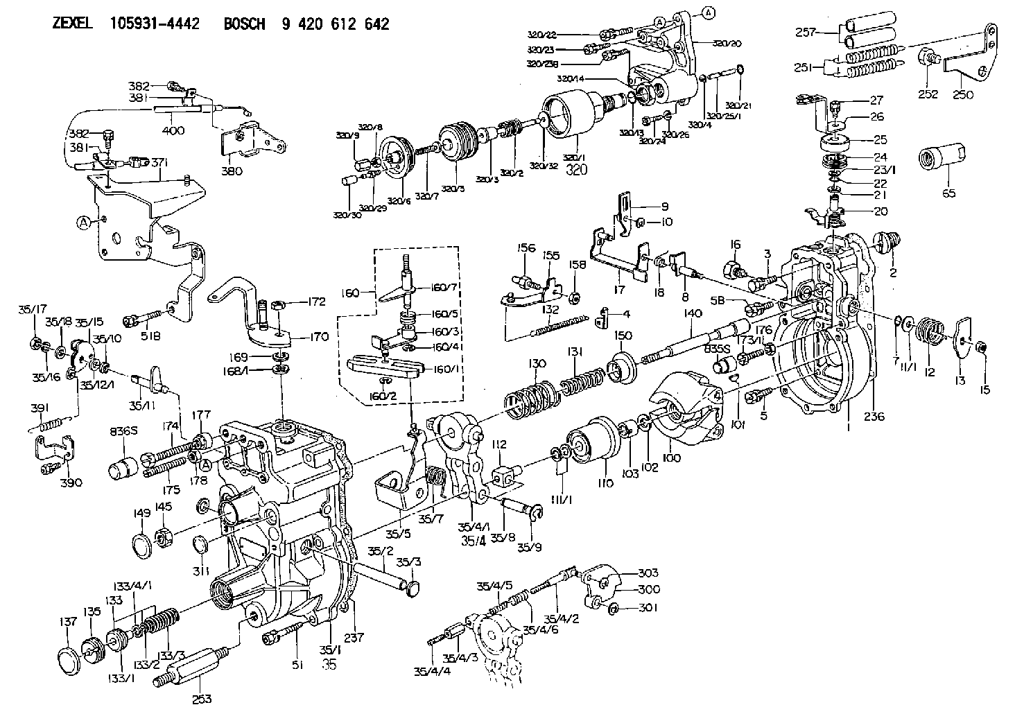
9 420 612 642
9420612642
ZEXEL
105931-4442
1059314442
ISUZU
8944733392
8944733392
Rating:
Scheme ###:
| 1. | [1] | 159200-3720 | GOVERNOR HOUSING |
| 2. | [1] | 154007-0200 | ADAPTOR |
| 3. | [1] | 020018-1840 | BLEEDER SCREW M8P1.25L18 |
| 4. | [1] | 159232-0201 | PLATE |
| 5. | [5] | 029010-6810 | BLEEDER SCREW |
| 5B. | [1] | 020106-1640 | BLEEDER SCREW M6P1.0L14 |
| 7. | [1] | 016530-1010 | O-RING |
| 8. | [1] | 159205-2321 | LEVER SHAFT |
| 9. | [1] | 159202-1802 | CONTROL LEVER |
| 10. | [1] | 016010-0810 | LOCKING WASHER |
| 11/1. | [0] | 029311-0220 | SHIM D18&10.3T0.2 |
| 11/1. | [0] | 029311-0230 | SHIM D18&10.3T0.5 |
| 11/1. | [0] | 029311-0430 | SHIM D18&10.3T0.30 |
| 11/1. | [0] | 029311-0440 | SHIM D18&10.3T0.40 |
| 11/1. | [0] | 029311-0450 | SHIM D18&10.3T0.25 |
| 11/1. | [0] | 029311-0460 | SHIM D18&10.3T0.35 |
| 11/1. | [0] | 139410-3300 | SHIM D18&10.3T0.6 |
| 11/1. | [0] | 139410-3400 | SHIM D18&10.3T0.8 |
| 11/1. | [0] | 139410-3500 | SHIM D18&10.3T0.9 |
| 12. | [1] | 159215-0000 | COILED SPRING |
| 13. | [1] | 159242-6601 | CONTROL LEVER |
| 15. | [1] | 013020-8040 | UNION NUT M8P1.25H7 |
| 16. | [1] | 159237-5200 | CAPSULE |
| 17. | [1] | 159202-2020 | CONTROL LEVER |
| 18. | [1] | 159215-0300 | COILED SPRING |
| 20. | [1] | 159242-0220 | CONTROL LEVER |
| 21. | [1] | 159242-0600 | BUSHING |
| 22. | [1] | 029631-0030 | O-RING &9.8W2.3 |
| 23/1. | [0] | 139410-1300 | SHIM D20.8&10.2T0.3 |
| 23/1. | [0] | 139410-1700 | SHIM D20.8&10.2T0.2 |
| 23/1. | [0] | 139410-1800 | SHIM D20.8&10.2T0.4 |
| 23/1. | [0] | 139410-2800 | SHIM D20.8&10.2T0.6 |
| 23/1. | [0] | 139410-3700 | SHIM D20.8&10.2T0.9 |
| 24. | [1] | 159215-4200 | COILED SPRING |
| 25. | [1] | 159235-6500 | CAP |
| 26. | [1] | 159242-9220 | CONTROL LEVER |
| 27. | [1] | 020006-1640 | BLEEDER SCREW M6P1L16 4T |
| 35. | [1] | 159251-8220 | GOVERNOR COVER |
| 35/1. | [1] | 159201-7320 | GOVERNOR COVER |
| 35/2. | [1] | 159205-0400 | LEVER SHAFT |
| 35/3. | [2] | 159237-0200 | CAPSULE |
| 35/4. | [1] | 159253-0720 | TENSIONING LEVER |
| 35/4/1. | [1] | 159203-0720 | TENSIONING LEVER |
| 35/4/2. | [1] | 159204-5021 | RACK |
| 35/4/3. | [1] | 159233-0300 | UNION NUT |
| 35/4/4. | [1] | 159234-0300 | FLAT-HEAD SCREW |
| 35/4/5. | [1] | 159216-0000 | COILED SPRING |
| 35/4/6. | [1] | 159216-0100 | COILED SPRING |
| 35/5. | [1] | 159203-5720 | GUIDE LEVER |
| 35/7. | [1] | 159215-1701 | COILED SPRING |
| 35/8. | [1] | 159231-2000 | BEARING PIN |
| 35/9. | [2] | 016010-0610 | LOCKING WASHER |
| 35/10. | [1] | 029620-8050 | PACKING RING |
| 35/11. | [1] | 159227-0320 | LEVER SHAFT |
| 35/12/1. | [0] | 029310-8280 | SHIM D16.5&8T0.1 |
| 35/12/1. | [0] | 029310-8320 | SHIM D16.5&8T0.2 |
| 35/12/1. | [0] | 029310-8340 | SHIM D16.5&8T0.3 |
| 35/12/1. | [0] | 029310-8360 | SHIM D16.5&8T0.5 |
| 35/12/1. | [0] | 029310-8660 | SHIM D16.5&8T0.6 |
| 35/12/1. | [0] | 029310-8670 | SHIM D16.5&8T1.0 |
| 35/15. | [1] | 159227-0520 | CONTROL LEVER |
| 35/16. | [1] | 014110-8440 | LOCKING WASHER |
| 35/17. | [1] | 029200-8190 | UNION NUT |
| 35/18. | [1] | 029300-8010 | PLAIN WASHER D15&8T1.00 |
| 51. | [5] | 020106-3840 | BLEEDER SCREW |
| 51B. | [2] | 020106-4540 | BLEEDER SCREW M6P1.0L45 |
| 65. | [1] | 154050-1720 | STOPPING DEVICE |
| 100. | [1] | 154100-5020 | FLYWEIGHT ASSEMBLY |
| 101. | [1] | 025803-1610 | WOODRUFF KEY |
| 102. | [1] | 029321-2020 | LOCKING WASHER |
| 103. | [1] | 029231-2030 | UNION NUT |
| 110. | [1] | 154123-2320 | SLIDING PIECE |
| 111/1. | [0] | 029311-0010 | SHIM D14&10.1T0.2 |
| 111/1. | [0] | 029311-0180 | SHIM D14&10.1T0.3 |
| 111/1. | [0] | 029311-0190 | SHIM D14&10.1T0.40 |
| 111/1. | [0] | 029311-0210 | SHIM D14&10.1T1 |
| 111/1. | [0] | 139410-0000 | SHIM D14.0&10.1T0.5 |
| 111/1. | [0] | 139410-0100 | SHIM D14.0&10.1T1.5 |
| 111/1. | [0] | 139410-3000 | SHIM D14&10.1T2.0 |
| 111/1. | [0] | 139410-3100 | SHIM D14&10.1T3.0 |
| 111/1. | [0] | 139410-3200 | SHIM D14&10.1T4.0 |
| 112. | [1] | 159236-0200 | TERMINAL STUD |
| 130. | [1] | 159210-6700 | GOVERNOR SPRING |
| 131. | [1] | 159211-3400 | GOVERNOR SPRING |
| 132. | [1] | 159214-0000 | COILED SPRING |
| 133. | [1] | 159212-6420 | SPRING PACK |
| 133/1. | [1] | 159234-5602 | GUIDE SLEEVE |
| 133/2. | [1] | 159212-5500 | COILED SPRING |
| 133/3. | [1] | 159212-6401 | COILED SPRING |
| 133/4/1. | [0] | 029310-9240 | SHIM D11.9&9T0.1 |
| 133/4/1. | [0] | 029310-9250 | SHIM D11.9&9T0.2 |
| 133/4/1. | [0] | 029310-9260 | SHIM D11.9&9T0.25 |
| 133/4/1. | [0] | 029310-9270 | SHIM D11.9&9T1.0 |
| 133/4/1. | [0] | 139409-0100 | SHIM D11.9&9T0.3 |
| 133/4/1. | [0] | 139409-0200 | SHIM D11.9&9T0.5 |
| 133/4/1. | [0] | 139409-0300 | SHIM D11.5&9T0.8 |
| 135. | [1] | 159248-2700 | FLAT-HEAD SCREW |
| 137. | [1] | 159237-5300 | CAPSULE |
| 140. | [1] | 159205-2101 | LEVER SHAFT |
| 145. | [1] | 159233-5700 | UNION NUT |
| 149. | [1] | 159237-5400 | CAPSULE |
| 150. | [1] | 159235-5300 | SLOTTED WASHER |
| 155. | [1] | 159204-5120 | STRAP |
| 156. | [1] | 159233-5800 | BLEEDER SCREW |
| 158. | [1] | 013020-5240 | UNION NUT M5P0.8H4 |
| 160. | [1] | 159252-0821 | LEVER GROUP |
| 160/1. | [1] | 159202-2200 | CONTROL LEVER |
| 160/2. | [1] | 016010-0810 | LOCKING WASHER |
| 160/3. | [1] | 159202-2120 | CONTROL LEVER |
| 160/4. | [1] | 016010-0810 | LOCKING WASHER |
| 160/5. | [1] | 159215-2301 | COILED SPRING |
| 160/7. | [1] | 159205-2222 | LEVER SHAFT |
| 168/1. | [0] | 139410-1200 | SHIM D26&10.2T0.3 |
| 168/1. | [0] | 139410-1900 | SHIM D26&10.2T0.2 |
| 168/1. | [0] | 139410-2000 | SHIM D26&10.2T0.4 |
| 168/1. | [0] | 139410-2400 | SHIM D26&10.2T0.35 |
| 168/1. | [0] | 139410-2500 | SHIM D26&10.2T0.25 |
| 168/1. | [0] | 139410-2900 | SHIM D26&10.2T0.6 |
| 169. | [1] | 139410-2100 | SHIM |
| 170. | [1] | 159241-1020 | CONTROL LEVER |
| 172. | [1] | 013020-8040 | UNION NUT M8P1.25H7 |
| 173/1. | [1] | 139006-3500 | BLEEDER SCREW M6P1.0L33 |
| 173/1. | [1] | 139006-3700 | BLEEDER SCREW M6P1.0L34 |
| 173/1. | [1] | 139006-3800 | BLEEDER SCREW M6P1.0L35 |
| 173/1. | [1] | 139006-3900 | BLEEDER SCREW M6P1.0L36 |
| 173/1. | [1] | 139006-5300 | BLEEDER SCREW M6P1.0L31 |
| 173/1. | [1] | 139006-5400 | BLEEDER SCREW M6P1.0L32 |
| 173/1. | [1] | 155615-2500 | BLEEDER SCREW M6P1.0L37 |
| 174. | [1] | 154010-8100 | BLEEDER SCREW M8P1.25L65 |
| 175. | [1] | 154010-0100 | FLAT-HEAD SCREW |
| 176. | [1] | 159225-8600 | UNION NUT |
| 177. | [1] | 154011-2300 | UNION NUT |
| 178. | [1] | 154011-0100 | HEXAGON NUT |
| 236. | [1] | 154390-0000 | GASKET |
| 237. | [1] | 159238-3100 | GASKET |
| 250. | [1] | 159225-1820 | BRACKET |
| 251. | [2] | 159243-4800 | COILED SPRING |
| 252. | [1] | 159248-0200 | BLEEDER SCREW |
| 253. | [1] | 159248-0401 | BLEEDER SCREW |
| 257. | [2] | 154156-0500 | TUBE |
| 300. | [1] | 159209-5200 | CAM PLATE |
| 301. | [1] | 016010-0840 | LOCKING WASHER |
| 303. | [1] | 016010-0540 | LOCKING WASHER |
| 311. | [1] | 159237-0200 | CAPSULE |
| 320. | [1] | 155423-8320 | ANEROID CAPSULE |
| 320/1. | [1] | 155423-7520 | DIAPHRAGM HOUSING |
| 320/2. | [1] | 155423-8200 | COILED SPRING |
| 320/3. | [1] | 155423-1800 | STOP PIN |
| 320/4. | [1] | 016010-0640 | LOCKING WASHER |
| 320/5. | [1] | 155403-3021 | BELLOWS |
| 320/6. | [1] | 155423-2000 | COVER |
| 320/7. | [1] | 155423-1500 | SCREW PLUG |
| 320/8. | [1] | 029240-6010 | UNION NUT M6P1.0H5* |
| 320/9. | [1] | 154035-1600 | CAP NUT |
| 320/13. | [1] | 016520-1510 | O-RING |
| 320/14. | [1] | 139220-0100 | UNION NUT |
| 320/20. | [1] | 155423-1701 | SPACER BUSHING |
| 320/21. | [1] | 159226-4500 | SPACER RING |
| 320/22. | [1] | 020118-3040 | BLEEDER SCREW |
| 320/23. | [3] | 020106-2240 | BLEEDER SCREW |
| 320/23B. | [1] | 020106-2540 | BLEEDER SCREW M6P1L25 |
| 320/24. | [1] | 139006-0900 | BLEEDER SCREW |
| 320/25/1. | [1] | 155423-1200 | STOP PIN L102 |
| 320/25/1. | [1] | 155424-4900 | STOP PIN L95 |
| 320/25/1. | [1] | 155424-5000 | STOP PIN L96 |
| 320/25/1B. | [1] | 155423-1300 | STOP PIN L102.5 |
| 320/25/1C. | [1] | 155423-1400 | STOP PIN L103 |
| 320/25/1D. | [1] | 155423-7600 | STOP PIN L103.5 |
| 320/25/1E. | [1] | 155423-7700 | STOP PIN L104 |
| 320/25/1F. | [1] | 155423-8700 | STOP PIN L97 |
| 320/25/1G. | [1] | 155423-8800 | STOP PIN L98 |
| 320/25/1H. | [1] | 155423-8900 | STOP PIN L99 |
| 320/25/1I. | [1] | 155423-9000 | STOP PIN L100 |
| 320/25/1J. | [1] | 155423-9100 | STOP PIN L101 |
| 320/26. | [1] | 014110-6440 | LOCKING WASHER |
| 320/29. | [1] | 139805-0000 | JOINT CONNECTION |
| 320/30. | [1] | 155424-0300 | CAP |
| 320/32. | [1] | 029311-2060 | SHIM D22&12.5T0.5 |
| 371. | [1] | 159226-2521 | BRACKET |
| 380. | [1] | 159225-8500 | BRACKET |
| 381. | [2] | 159225-7201 | CLAMPING BAND |
| 381. | [2] | 159225-7201 | CLAMPING BAND |
| 382. | [2] | 020146-1240 | BLEEDER SCREW M6P1.0L12 |
| 382. | [2] | 020146-1240 | BLEEDER SCREW M6P1.0L12 |
| 390. | [1] | 159226-2620 | BRACKET |
| 391. | [1] | 159225-6800 | COILED SPRING |
| 400. | [1] | 159225-7301 | WIRE |
| 835S. | [1] | 154062-1900 | CAP D12L24 |
| 836S. | [1] | 154062-1700 | CAP D20L32 |
Include in #1:
101401-4150
as GOVERNOR
Cross reference number
Zexel num
Bosch num
Firm num
Name
Information:
5. Install a 3/8"-16 NC forged eyebolt in the top of the BrakeSaver housing, and fasten a hoist to it.6. Install tooling (A) on the BrakeSaver housing and rotor. Tooling (A) holds the BrakeSaver housing and rotor assembly together at removal. This prevents damage to the rotor rings and seals.7. Remove bolts (6) that hold BrakeSaver housing (7) to the flywheel housing.8. Use bolts (4) as forcing screws, and tighten the bolts evenly to remove BrakeSaver housing (7) from the flywheel housing. The weight is 86 kg (190 lb.).Install BrakeSaver
1. Install tooling (A) on the BrakeSaver housing and rotor. Tooling (A) holds the BrakeSaver housing and rotor assembly together at installation. This prevents damage to the rotor rings and seals.2. Install a 3/8"-16 NC forged eyebolt in the top of the BrakeSaver housing, and fasten a hoist to it.3. Install two 5/8"-18 guide bolts (3) in the crankshaft as shown. Make sure dowel (2) is in alignment with the dowel hole in the rotor assembly, and put BrakeSaver housing (1) in position in the flywheel housing.4. Install the three bolts that hold the BrakeSaver housing to the flywheel housing. Remove tooling (A) and guide pins (3). 5. Connect the oil line to fitting (6).6. Inspect the O-ring seals for damage, and make replacements if needed. Install O-ring seals (4) and (5). Put clean engine oil on the O-ring seals.7. Install manifold (7) into the BrakeSaver control valve, and install the four bolts that hold the manifold to the BrakeSaver housing. 8. Connect BrakeSaver lubrication oil line (8) to the fitting in the BrakeSaver housing.END BY:a. install flywheel (BrakeSaver)Disassemble BrakeSaver
START BY:a. remove BrakeSaver1. Remove tooling (A) from the BrakeSaver housing and rotor. Tooling (A) prevents damage to the rotor seals and rings during removal of the BrakeSaver housing. 2. Remove bolts (1) from gear plate (2). Remove the plate. 3. Put alignment marks on stator (3) and housing (4) for assembly purposes. Remove bolts (5) and the stator. 4. Turn the stator over, and remove spiral ring (6). 5. Turn the stator over again. Remove sleeve assembly (9). Remove O-ring seal (7) and lip-type seal (8) from the sleeve. 6. Remove O-ring seal (11) and the six smaller O-ring seals from the oil holes on the housing.7. Remove rotor assembly (12).8. Remove seal ring (10) from both sides of the rotor. 9. Remove carrier (13) and wear sleeve (14) with tooling (B) from both sides of the rotor. 10. Remove spiral ring (15). Turn the housing over, and remove sleeve assembly (17). Remove the lip-type seal and O-ring seal (16) from the sleeve.Assemble BrakeSaver
1. Inspect the O-ring seals for damage, and make replacements if needed. Put clean engine oil on the O-ring seals. 2. Install O-ring seal (2) on sleeve (1).3. Install the sleeve in the BrakeSaver housing. Make an alignment of the notch (3) on the sleeve with the notch in the housing, and install the dowel.
Make certain there is clearance behind the spiral ring when it is